
APPUSB150 - Network card / adapter Approx - Free user manual and instructions
Find the device manual for free APPUSB150 Approx in PDF.


| Product Type | Wireless Network Adapter |
| Model | APPUSB150 |
| Brand | Approx |
| Wireless Standards | IEEE 802.11b/g/n |
| Maximum Data Rate | 150 Mbps |
| Interface | USB 2.0 |
| Frequency Band | 2.4 GHz |
| Security | WEP 64/128-bit, WPA/WPA2, TKIP/AES, 802.1x |
| WPS Support | Yes (PBC and PIN methods) |
| Operating Systems Supported | Windows 2000, XP (32/64), Vista (32), Windows 7 (32/64) |
| Dimensions (approx.) | 2.5 x 1.5 x 0.5 cm |
| Weight (approx.) | 10 g |
| Power Supply | USB bus powered |
| Operating Temperature | 0°C to 40°C |
| Storage Temperature | -40°C to 70°C |
| Operating Humidity | 10% to 90% RH (non-condensing) |
| Certifications | FCC, CE |
| LED Indicator | Green/Yellow: connection and activity |
| Package Contents | Adapter, USB cable, Quick Installation Guide, Resource CD |
| Care and Cleaning | Keep dry; clean with a soft, dry cloth |
| Safety Warnings | Do not use outdoors in France; avoid co-location with other antennas |
| Spare Parts Availability | Not available; contact distributor for replacements |
Frequently Asked Questions - APPUSB150 Approx
User questions about APPUSB150 Approx
0 question about this device. Answer the ones you know or ask your own.
Ask a new question about this device
Download the instructions for your Network card / adapter in PDF format for free! Find your manual APPUSB150 - Approx and take your electronic device back in hand. On this page are published all the documents necessary for the use of your device. APPUSB150 by Approx.
USER MANUAL APPUSB150 Approx
Imagen 2-1
Imagen 2-2
Imagen 2-3
Imagen 2-4
Imagen 2-5
Imagen 2-6
Imagen 2-7

Nota:
Figure 2-9
2.2.2 Windows Vista
Imagen 2-10
Imagen 2-11
Figure 2-12
Nota:
Figure 2-13
Imagen 2-14
2.2.3 Windows 7
Imagen 2-15
Imagen 2-16
Figure 2-17

Nota:
Figure 2-18
Imagen 2-19
Figure 3-1
Imagen 3-2
Imagen 3-3
Imagen 3-4
WPA/WPA2: Wi-Fi Protected Access
WPA/WPA2 Passphrase: Wi-Fi Protected Access Passphrase
802.1x: Activa la seguridad 802.1x.
Imagen 3-5
Note:
Imagen 3-7
3.1.2.2 Eliminar un perfil
Imagen 3-10
3.1.2.7 Auto Profile Selection Management
Imagen 3-11
Imagen 3-12
Imagen 3-13
3.2 Windows Vista
Imagen 3-19
Imagen 3-20
Imagen 3-21
Imagen 4-1
Imagen 4-3
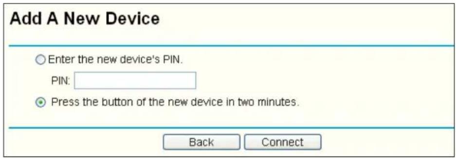
Imagen 4-4
Imagen 4-5
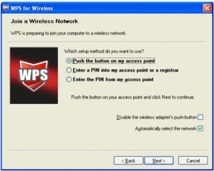
Imagen 4-6
Imagen 4-7
4.2 Método PIN
Figure 4-8
Figure 4-9
Figure 4-10
This equipment has been tested and found to comply with the limits for a Class B digital device, pursuant to part 15 of the FCC Rules. These e limits are designed to provide reasonable protection against harmful interference in a re-sidential installation. This equipment generates uses and can radiate radio frequency energy and, if not installed and used in accordance with the instructions, may cause harmful interference to radio communications. However, there is no guarantee that interference will not occur in a particular installation. If this equipment does cause harmful interference to radio or television reception, which can be determined by turning the equipment off and on, the user is encouraged to try to correct the interference by one or more of the following measures:
• Reorient or relocate the receiving antenna.
- Increase the separation between the equipment and receiver.
- Connect the equipment into an outlet on a circuit different from that to which the receiver is connected.
- Consult the dealer or an experienced radio/ TV technician for help.
This device complies with part 15 of the FCC Rules. Operation is subject to the following two conditions:
1) This device may not cause harmful interference.
2) This device must accept any interference received, including interference that may cause undesired operation.
Any changes or modifications not expressly approved by the party responsible for compliance could void the user's authority to operate the equipment.
FCC RF Radiation Exposure Statement:
This device has been tested for compliance with FCC RF Exposure (SAR) limits in the typical laptop computer configuration and this device can be used in desktop or laptop computers. This device cannot be used with handheld PDAs (personal digital assistants). This device and its antenna must not be co-located or operated in conjunction with any other antenna or transmitter. SAR measurements are based on a 5mm spacing from the body and that compliance is achieved at that distance.
CE Mark Warning

This is a class B product. In a domestic environment, this product may cause radio interference, in which case the user may be required to take adequate measures.
National restrictions
This device is intended for home and office use in all EU countries (and other countries following the EU directive 1999/5/EC) without any limitation except for the countries mentioned below:
| Country | Restriction | Reason/remark |
| Bulgaria | None | General authorization required for outdoor use and public service |
| France | Outdoor use limited to 10 mW e .i.r.p. within the band 2454-2483.5 MHz | Military Ra diolocation use. Refarming of the 2.4 GHz band has been ongoing in recent years to allow current relaxed regulation. Full implementation planned 2012 |
| Italy | None | If used outside of own premises, general authorization is required |
| Luxembourg | None | General authorization required for net work and service supply(not for spectrum) |
| Norway | Implemented | This subsection does not apply for the geographical area within a radius of 20 km from the centre of Ny-Ålesund |
| Russian Federation | None | Only for indoor applications |
Note: Please don't use the product outdoors in France.
CONTENTS
Package Contents
Chapter 1. Introduction
1.1 Overview of the product
1.2 Features
1.3 LED Status
Chapter 2. Installation Guide
2.1 Hardware Installation
2.2 Software Installation
2.2.1 For Windows XP
2.2.2 For Windows Vista
2.2.3 For Windows 7
Chapter 3. Configuration Guide
3.1 For Windows XP
3.1.1 Current Status
3.1.2 Profile Management
3.1.3 Diagnostics
3.2 For Windows Vista
3.3 For Windows 7
Chapter 4. WPS configuration
4.1 PBC (Push Button Configuration) method
4.2 PIN method
4.2.1 Enter a PIN into your AP device
4.2.2 Enter the PIN from your AP device
Appendix A: Specifications
Appendix B: Glossary
Package Contents
The following contents should be found in your box:
One APPUSB150 150Mbps Wireless Lite-N USB Adapter
Quick Installation Guide
One Resource CD for APPUSB150, including:
- APPUSB150 Wireless Lite-N Client Utility (AWCU) and Drivers
- User Guide
• Other Helpful Information

Note:
Make sure that the package contains the above items. If any of the listed items are damaged or missing, please contact with your distributor.
Chapter 1. Introduction
Thank you for choosing APPUSB150 150Mbps Wireless Lite-N USB Adapter.
1.1 Overview of the product
The adapter is designed to provide a high-speed and unrivaled wireless performance for your notebook and PC. With a faster wireless connection, you can get a better Internet experience, such as downloading, gaming, video streaming and so on.
The APPUSB150's auto-sensing capability allows high packet transfer rate of up to 150Mbps for maximum throughput. It has good capability on anti-ja mming; it can also in teroperate with other wireless (802.11b/g) products. The adapter supports WEP, WPA and WPA2 encryption to prevent outside intrusion and protect your personal information from being exposed.
The Quick Setup Wizard guides you step by step through the installation process; the APP150 Wireless Lite-N Client Utility helps you create a wireless connection immediately.
With unmatched wireless performance, reception, and security protection, the APPUSB150 is the best choice for easily adding or upgrading wireless connectivity.
1.2 Features
➢ IEEE802.11g, IEEE802.11b, IEEE802.11n standards
Supports WPA/WPA2 data security, IEEE802. 1x authentication, TK IP/AES encryption, WEP encryption
Make use of IEEE 802.11n wireless technology to provide a wireless data rate of up to 150Mbps
Supports automatically adjust to lower speeds due to distance or other operating limitations
Provides USB interface
Supports Ad-Hoc and Infrastructure modes
Good capability on anti-jamming
Supports roaming between access points when configured in Infrastructure mode
Easy to configure and provides monitoring information
Supports Windows® 200 0, Windows® XP (32/64), Windows® Vista (32), Windows® 7 (32/64)
1.3 LED Status
| LED Status Working Status | |
| OFF The driver has not been installed | |
| Flashing slowly | The driver has been installed but there is no data being transmitted or received |
| Flashing quickly There is data being transmitted or received |
Chapter 2. Installation Guide
2.1 Hardware Installation
There are two ways to install the Adapter:
- Plug the Adapter directly to the USB port on your computer.
- Connect the Adapter and your computer through the USB cable attached in package.
Note:
The promoted Found New Hardware Wizard screen will pop up when the adapter is installed correctly. Click Cancel.
2.2 Software Installation
2.2.1 For Windows XP
The Setup steps for Wind ows 2000 and XP are similar with each other. This u ser guide takes Windows XP for example.
- Insert the Resource CD into your CD-ROM drive. To continue, double-click My Computer, and then do uble-click the CD/DVD drive wh ere the installation CD was placed. Op en APPUSB150 folder, and double-click Setup.exe. Then you will see Figure 2-1.
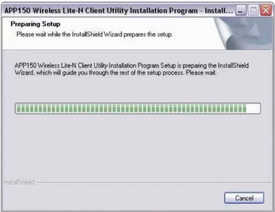
Figure 2-1
- Soon, Figure 2-2 will display after a moment. Click Next to continue.
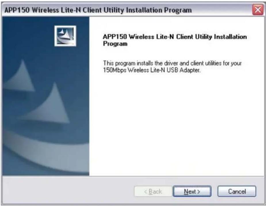
Figure 2-2
- After that, you should choose a Setup type. It is recommended that you select Install Client Utilities and Driver. Select Install Driver Only to install driver only, select Make Driver Installation Diskette(s) to make the diskette(s) as the installation driver (shown in Figure 2-3). Click Next to continue.
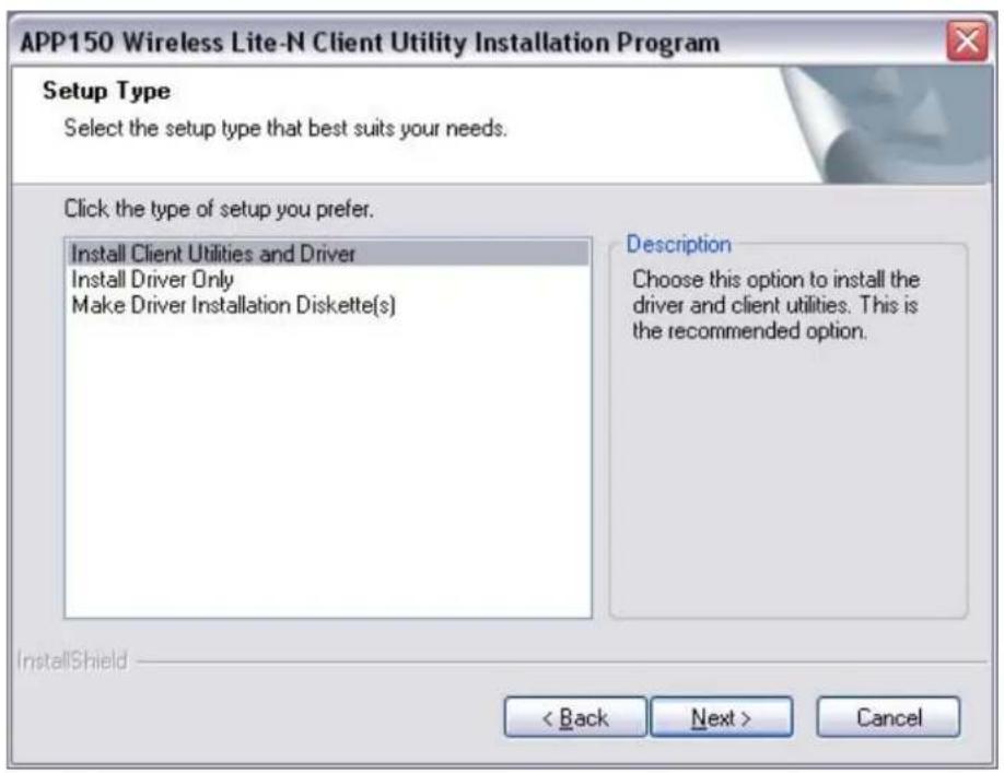
Figure 2-3
- C lick Browse... to change the destination locati on for the software, then click Next in the screen below (shown in Figure 2-4).
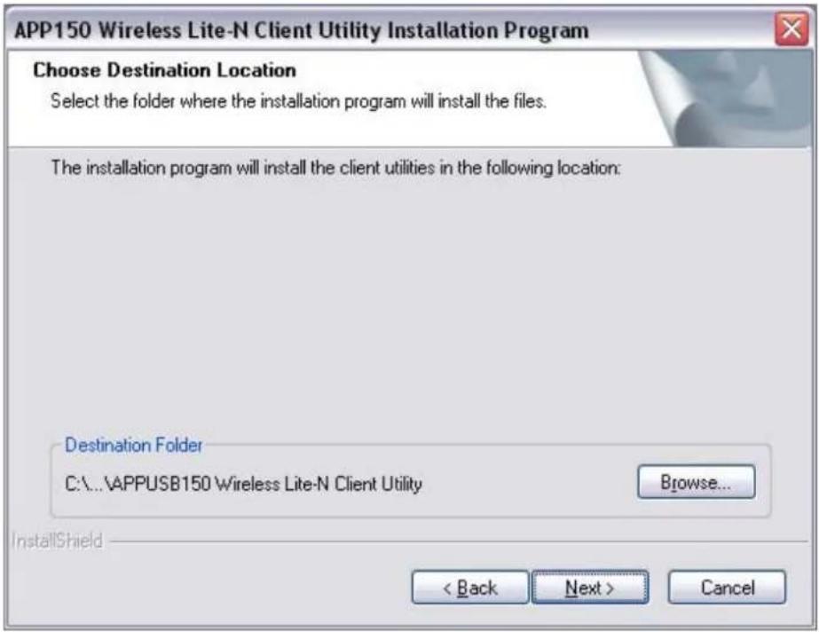
Figure 2-4
- After that, select the program folder, you should create a new folder name or select one from the Existing Folders list. It is recommended that you keep the default setting. Click Next to continue the installation.

Figure 2-5
- Choose configuration tool, if you are not sure, plea se leave it d eault. Then click Next to continue.
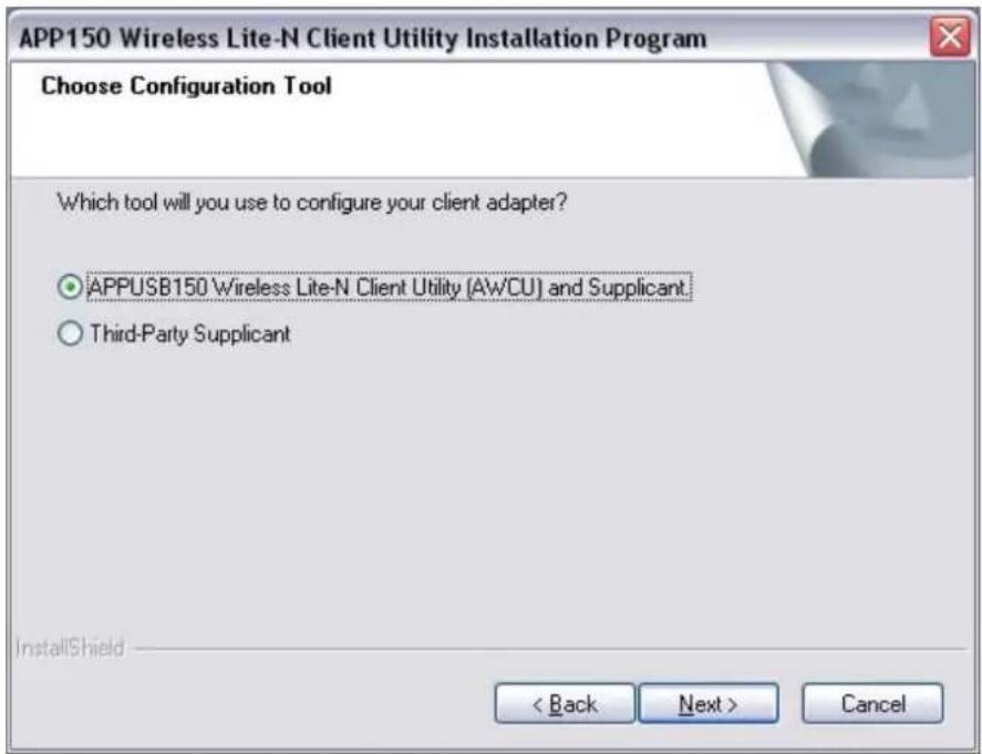
Figure 2-6
- C lick OK to continue the Installation. Wait a while for the setup as shown in Figure 2-7.
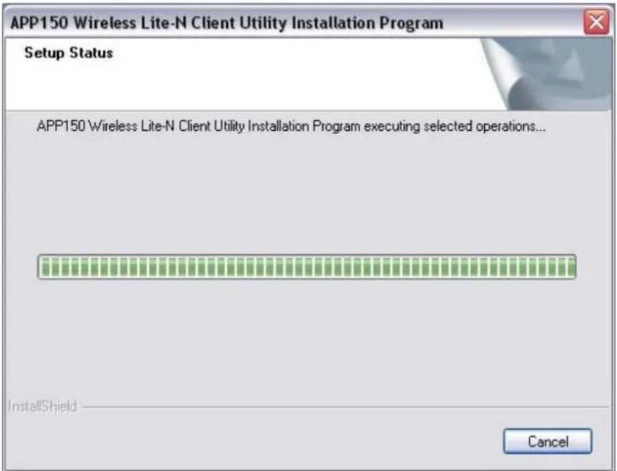
Figure 2-7

Note:
For Windows XP, the Se tup Wizard will notify you of how to proceed with the installation during these steps (shown in Figure 2-8). Our drivers have been tested thoroughly, and are able to work with the operating system. Click Continue Anyway to continue the Installation.
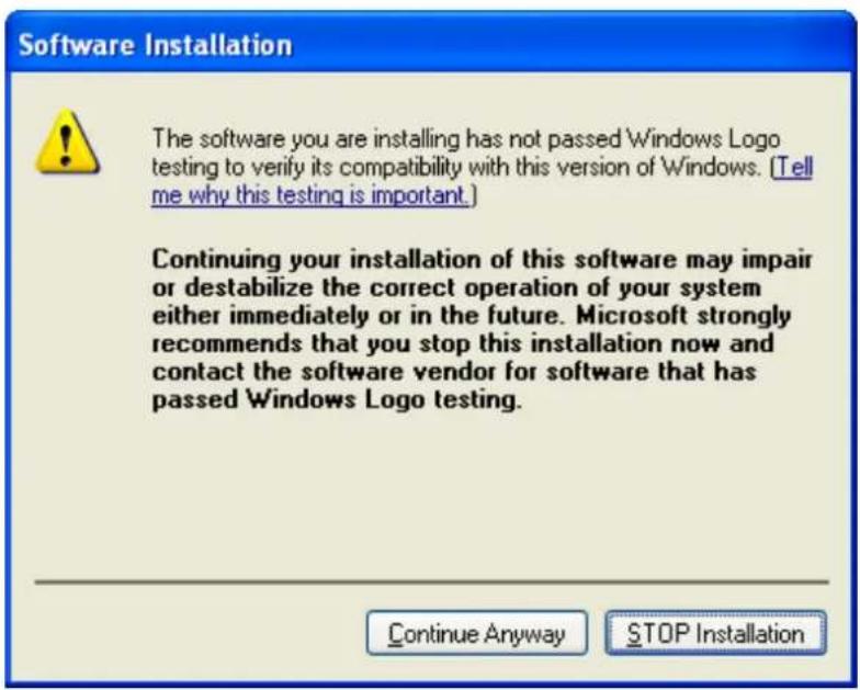
Figure 2-8
- After all the steps above, you will see the screen below, click Finish to reboot the system.
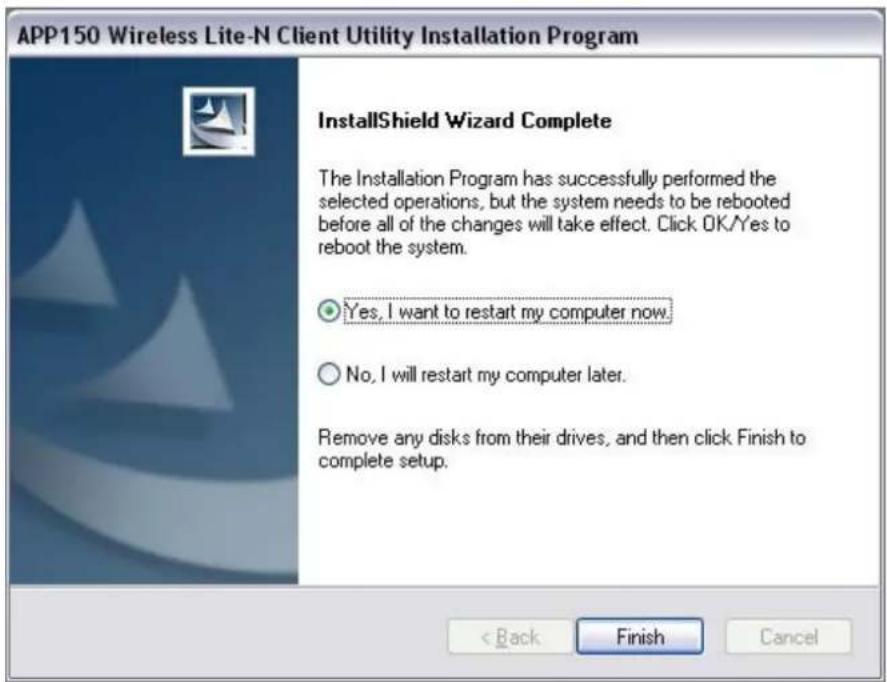
Figure 2-9
2.2.2 For Windows Vista
- Insert the Resource CD into your CD-ROM drive. To continue, double-click My Computer, and then do uble-click the CD/DVD drive where the installation CD was placed. Op en APPUSB150 folder, and double-click Setup.exe. Then you will see Figure 2-10.
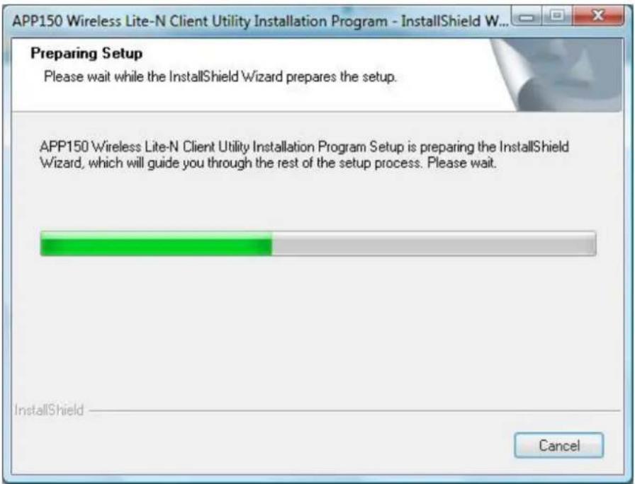
Figure 2-10
- Soon, Figure 2-11 will display after a moment. Click Next to continue.
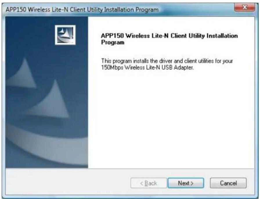
Figure 2-11
- Wait a while for the setup as shown in Figure 2-12.

Figure 2-12
Note:
For Windows Vista, the Setup Wizard will not fy you about the Windows Security with the installation during these steps (shown in Figure 2-13). Our drivers have been tested thoro ughly, and are able to work with the operating system. Click Installation this driver software anyway to continue the Installation.
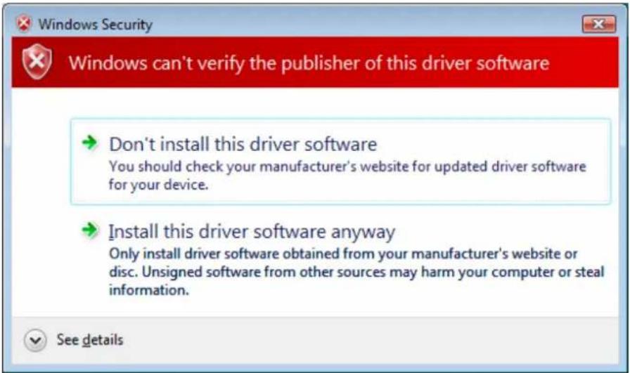
Figure 2-13
- Then you will see Figure 2-14. Click Finish to complete.
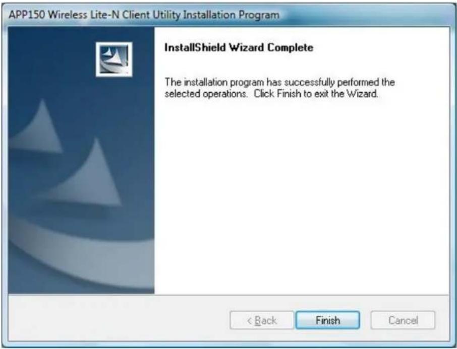
Figure 2-14
2.2.3 For Windows 7
- Insert the Resource CD into your CD-ROM drive. To continue, find the CD/DVD drive where the installation CD was placed. Open APPUSB150 folder, and double-click Setup.exe. Then you will see Figure 2-15.
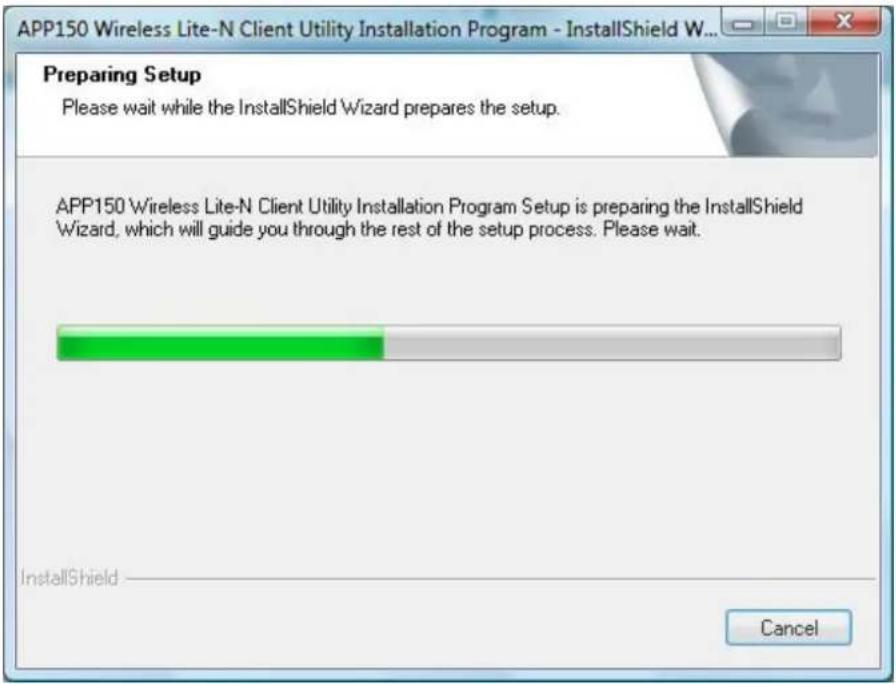
Figure 2-15
- Soon, Figure 2-16 will display after a moment. Click Next to continue.

Figure 2-15
- Wait a while for the setup as shown in Figure 2-12.

Figure 2-16
Note:
For Windows® 7, the Setup Wizard will notify you about the Windows Security with the installation during these steps (shown in Figure 2-13). Our drivers have been tested thoroughly, and are able
to work with the operating system. Click Installation this driver software anyway to continue the Installation.
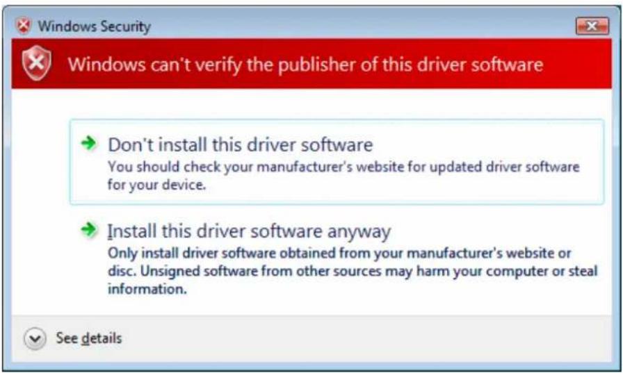
Figure 2-17
- Then you will see Figure 2-14. Click Finish to complete.
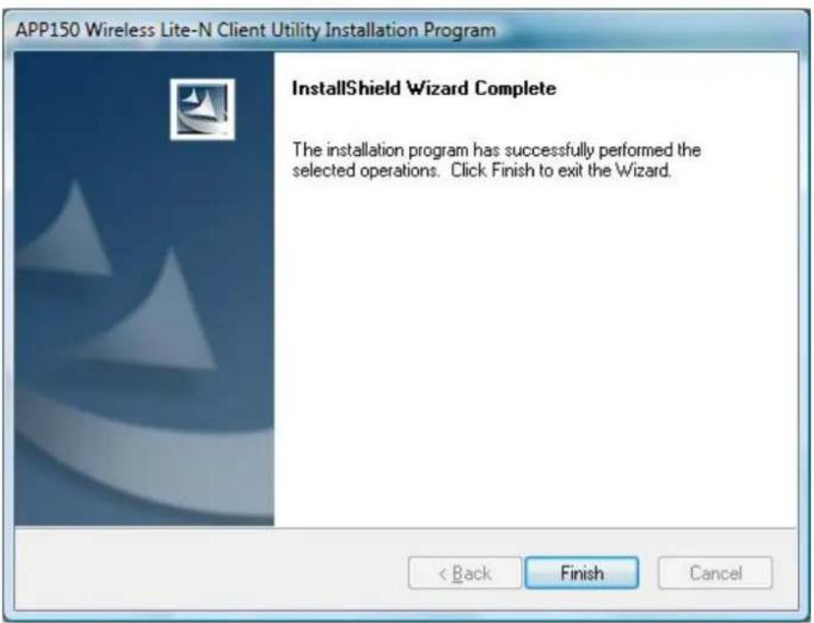
Figure 2-18
Chapter 3. Configuration Guide
3.1 For Windows XP
APPUSB150 can be configured by APP150 Wireless Lite-N Client Utility (AWCU) in Windows XP & 2000. This chapter describes how to configure your Adapter for wireless connectivity on your Wireless Local Area Network (WLAN) and use the data security encryption features.
The configuration of the adapter in Windows XP is similar with that of Windows 2000. This User Guide takes Windows XP for example.
After In stalling the Adapter, the Ada pter's tray icon will appear in your system tray. It appears at the bottom of the screen, and shows the signal strength using color and the received signal strength indication (RSSI).
If the icon is gray, there is no connection.
If the icon is red, there is poor signal strength and the RSSI is less than 5dB.
If the icon is yellow, there is poor signal strength and the RSSI is between 5dB and 10dB.
If the icon is green, there is good signal strength and the RSSI is between 10dB and 20dB.
If the icon is green, there is excellent signal strength and the RSSI is more than 20dB.
Double-click the icon and the AWCU will run. You can also run the utility by clicking the Start→
Program→Wireless→APPUSB150 Wireless Lite-N Client Utility→APPUSB150 Wireless
Lite-N Client Utility. The AWCU provides some integrated and easy tools to:
➢ Display current status information
- Edit and add configuration profiles
▶ Display current diagnostics information
The section below introduces these above capabilities.
3.1.1 Current Status
The Current Status tab contains general information about the program and its operations. The Current Status tab needn't any configurations.
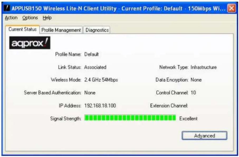
Figure 3-1
The following table describes the items found on the Current Status screen.
Profile Name - This shows the name of current selected configuration profile. The configuration of Profile name will be described on the General tab of Profile Management.
Link Status - This shows whether the station is associated to the wireless network.
Wireless Mode - Here displays the wireless mode.
Network Type - The type of network and the station currently connected are shown here. The options include:
• Infrastructure (access point)
- Ad Hoc
Note:
You can configure the network type and wireless mode on the Advanced tab of Profile Management.
IP Address - This displays the computer's IP address.
Control Channel - This shows the currently connected channel.
Data Encryption - Here displays the encryption type the driver is using. You can configure it on the Security tab of Profile Management.
Server Based Authentication - This shows whether the server based authentication is used.
Signal Strength - This shows the strength of the signal.
Click Advanced on the screen above, you can see advanced information about the program
and its operations.
3.1.2 Profile Management
Click the Profile Management tab of the AWCU and the next screen will appear (shown in Figure 3-2). The Profile Management screen provides tools to:
▶ Add a new profile
Modify a profile
Remove a profile
Activate a Profile
Import a Profile
Export a Profile
➢ Scan Available Networks
Order profiles
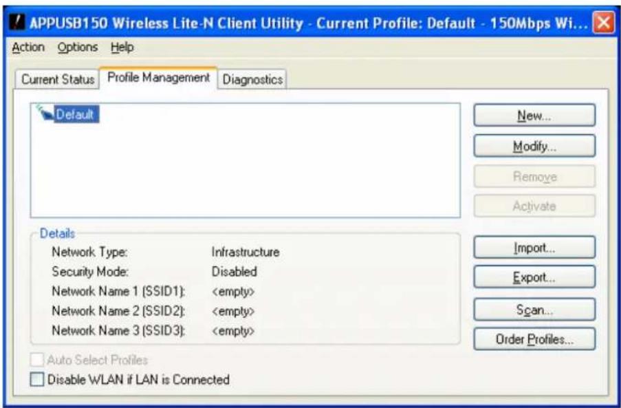
Figure 3-2
3.1.2.1. Add or Modify a Configuration Profile
To add a new configuration profile, click New on the Profile Management tab. To modify a configuration profile, select the configuration profile from the Profile list and click Modify. Then you will see the Management dialog box (shown in Figure 3-3).
1. Edit the General tab
Profile Name - Please enter the Profile name which identifies the configuration profile. This name must be unique. Note that the profile names are not case-sensitive.
➢ Client Name - Please enter the Profile name which identifies the client machine.
Network Names (SSIDs) - Please enter the IEEE 802.11 wireless network name. This
field has a maximum limit of 32 characters.
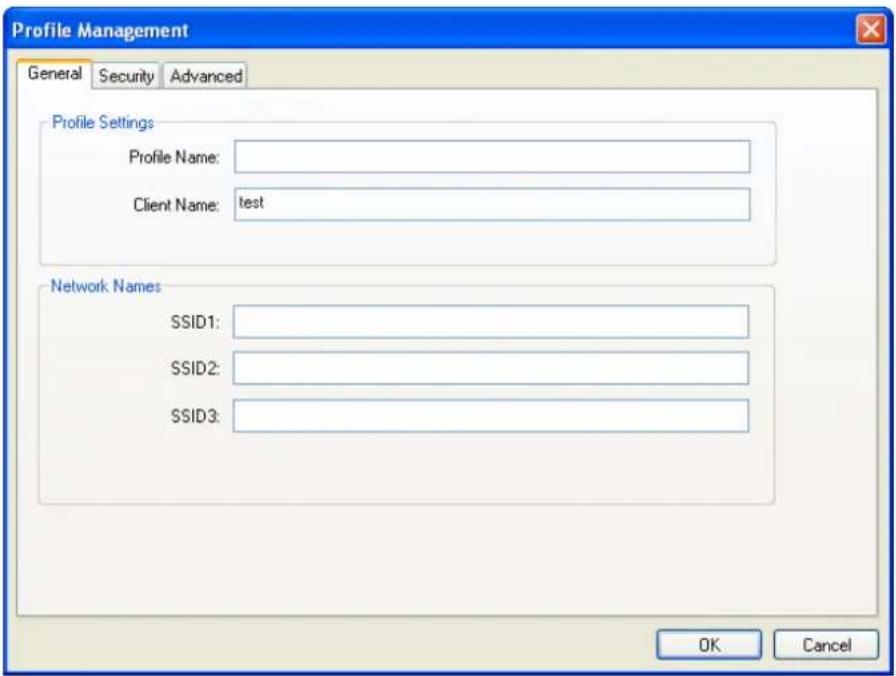
Figure 3-3
2. Edit the Security tab
Select the Security tab in the screen above, and then you can edit the fields to configure the profile. To define the security mode, select the radio button of the desired security mode as follows.
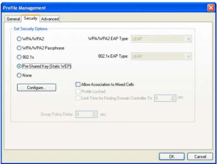
Figure 3-4
WPA/WPA2: Wi-Fi Protected Access
WPA/WPA2 Passphrase: Wi-Fi Protected Access Passphrase
802.1x: Enables 802.1x security.
Pre-Shared Key (Static WEP): Enables the use of shared keys that are defined on both the access point and the station. To define shared encryption keys, choose the Shared Key radio button and click Configure to fill in the Define Shared Keys window (shown in Figure 3-5).
None: No se curity (not recommended).
Note:
If the access point which the Adapter is associated has WEP set and the client has WEP enabled, make sure that Allow Association to Mixed Cells is checked on the Security tab to allow association. To complete WEP encryption configuration, you must select the 802.1 Authentication Mode as appropriate on the Advanced tab of this Profile Management dialog.
To configure the Encryption Keys under the Pre-Shared keys (Static WEP) Security mode:
![Configure Pre-Shared Keys (Static WEP) Key Entry Hexadecimal [0-9, A-F] ASCII Text (all keyboard characters) Encryption Keys Transmit Key WEP Key Size: 64 128 152 WEP Key 1: WEP Key 2: WEP Key 3: WEP Key 4: OK Cancel](/content/2026/06/1237605/images/b627eebcbf78d271ad7c3d9acfbf2bf23d8504eed728d99ba2b273a1c7fdce80.jpg)
Figure 3-5
Note:
Select different Security Options, the configurations are different; you can select the appropriate security option and configure the exact key as your need.
3. Edit the Advanced tab
This screen below allows you to make advanced configuration for the profile.
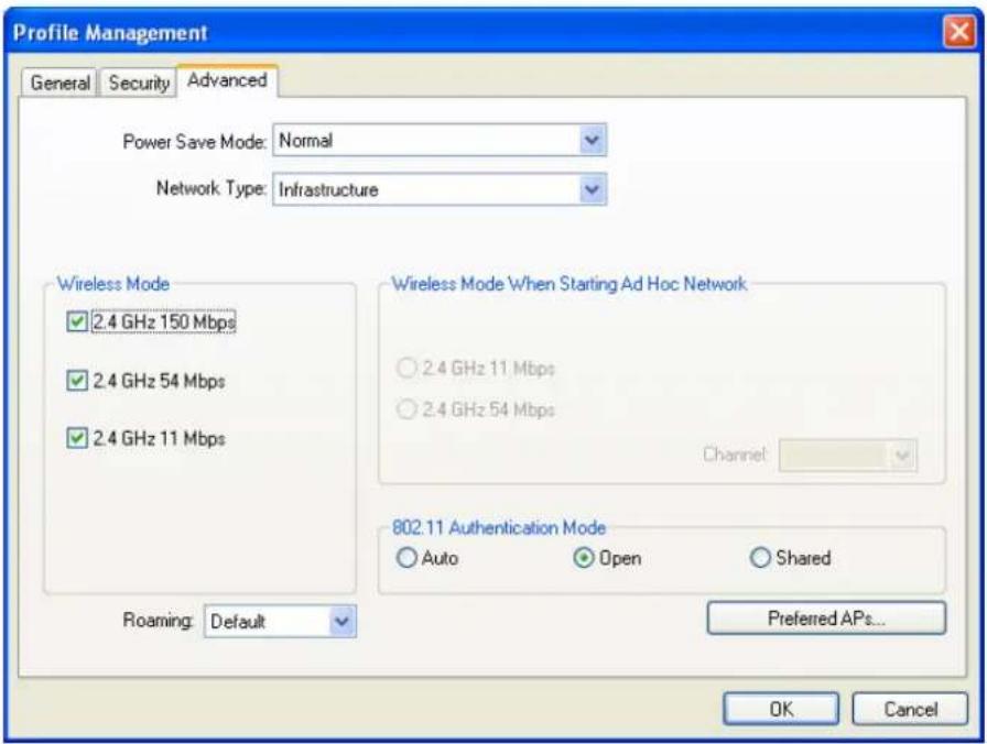
Figure 3-6
Power Save Mode - Please select the power save mode in the drop-down list.
- Maximum - Selects maximum mode to let the access point buffer incoming messages for the Adapter. The Adapter will detect the access point if any messages are waiting periodically.
- Normal - Normal mode uses maximum when retrieving a large number of packets, then switches back to power save mode after retrieving the packets.
- Off - Turns power saving off, thus powering up the Wireless USB Adapter continuously for a short message response time.
Network Type - There are basically two modes of networking:
• Infrastructure - All wireless clients will connect to an access point or wireless router.
- Ad-Hoc - Directly connecting to another computer, for peer r-to-peer communication, using wireless network adapters on each computer, such as two or more APPUSB150 wireless adapters.
Note:
1) An Infrastructure network k contains an Access Point or wireless router. All the wireless devices or clients will connect to the wireless router or access point.
2) An Ad-Hoc network contains only clients, such as laptops with wireless desktop adapters. All the adapters must be in Ad-Hoc mode to communicate.
Wireless Mode - Specifies 2.4 GHz 150 Mbps, 2.4 GHz 54 Mbps or 2.4 GHz 11 Mb ps operation in an access point network. The Wireless adapter must match the wireless mode of the access point with which it associates.
Wireless Mode when Starting an Ad Hoc Network - Specifies 2.4 GHz 54/11 Mbps to start an Ad Hoc network if no matching network name is found after scanning all available modes. This mode also allows the selection of the channel that the Wireless Adapter uses. The channels available depend on the regulatory domain. If the adapter finds no other ad hoc adapters, the channel that the adapter starts the ad hoc network with will be selected automatically. The Adapter must match the wireless mode and channel of the clients it associates.
802.11 Authentication Mode - Select which mode the Adapter uses to authenticate to an access point:
- Auto - Automatic causes the adapter to attempt authentication using shared, but switches it to open authentication if shared fails.
- Open - Open System enables an ad apter to a ttempt authentication regardless of its WEP settings. It will only associate with the access point if the WEP keys on both the adapter and the access point match.
- Shared - Shared-key only allows the adapter to associate with access points that have the same WEP key.
For infrastructure (access point) networks, click Preferred APs... to specify four access points at most to the client ad apter that attempt s to be associated to the access point s. The four access points have different priorities; the frontal has the higher priority.
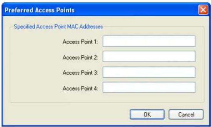
Figure 3-7
3.1.2.2. Remove a profile
- Go to the Profile Management tab (shown in Figure 3-2).
- Select the profile name in the Profiles List.
- C lick Remove.

Note:
The profile being used can't be removed.
3.1.2.3. Switch another Profile
-
Go to the Profile Management screen (shown in Figure 3-2).
-
Select the profile name required in the Profiles List.
-
C lick Activate.
3.1.2.4. Export a Profile
-
From the Profile Management screen (shown in Figure 3-2), highlight the profile to export.
-
C lick Export..., the Export Profile window will then appear below.
-
Browse the directory to export the profile to.
-
C lick Save. The profile should then exported to the specified location.
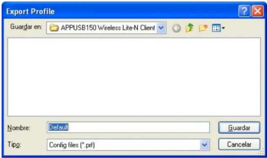
Figure 3-8
3.1.2.5. Import a Profile
-
From the Pr ofile Management screen (shown in Figure 3-2), click Import.... Then the Import Profile will appear below.
-
Browse to the directory where the profile is located.
-
Highlight the profile name.
-
C lick Open, the imported profile will then appear in the Profiles List.
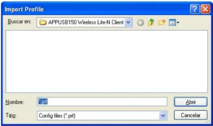
Figure 3-9
3.1.2.6. Scan Available Networks
- C lick Scan on the Profi le Manag ement screen (shown in Figure 3-2), t he Availa ble Infrastructure and Ad Hoc Networks window will appear below.
- C lick Refresh to refresh the list at any time.
- Highlight a network name and click Activate to connect to an available network. If no configuration profile exists for that network, the Profile Management window will open the General tab screen. Fill in the Profile name and click OK to create the configuration profile for that network.
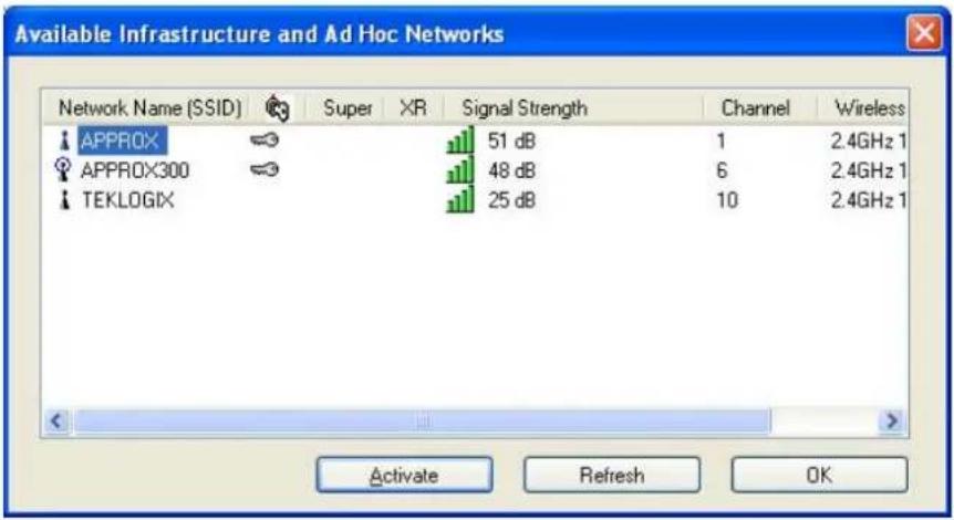
Figure 3-10
3.1.2.7. Auto Profile Selection Management
The auto selection feature allows the adapter to automatically select a profile from the list of profiles and use it to connect to the network. To add a new profile into the Auto Selected Profiles list, please follow these steps.
-
On the Profile Management screen (shown in Figure 3-2), click Order Profiles....
-
The Auto Profiles Selection management window will appear (shown in Figure 3-11) with a list of all created profiles in the Available Profiles.
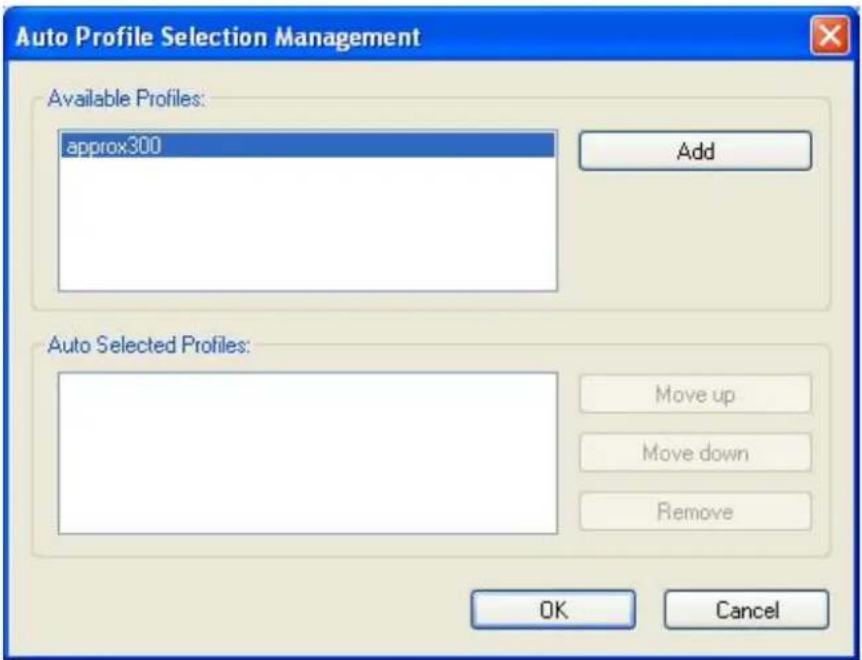
Figure 3-11
- Highlight the profiles to add to auto profile selection, and click Add. The profile will appear in the Auto Selected Profiles box.
- Highlight a profile in the Auto Selected Profiles box.
- C lick Move Up or Move Down as appropriate.
Note:
The first profile in the Auto Selected Profiles box has highest priority, while the last profile has the lowest priority.
-
C lick OK.
-
Check the Auto Select Profiles checkbox on the Profile Management tab (show n in Figure 3-2).
Note:
When auto profile selection is enabled by checking Auto Select Profiles on the Profile Management tab, the client adapter will scan for an available e network. The profile with the highest priority and the same SSID a s one of t he found networks will be u sed to connect to the network. If the connection fails, the client adapter will try the next h ghest priority profile that matches the SSID until an available network is found.
3.1.3 Diagnostics
The Diagnostics tab of the APP150 Wireless Li te-N Client Utility (AWCU) provides buttons used to retrieve receiving and transmitting statistics. The Diagnostics tab does not require any configuration.
The Diagno stics tab lists the following receiving and transmitting diagnostics for frames received or transmitted by the wireless network adapter:
▶ Multicast frames transmitted and received
▶ Broadcast frames transmitted and received
▶ Unicast frames transmitted and received
▶ Total bytes transmitted and received
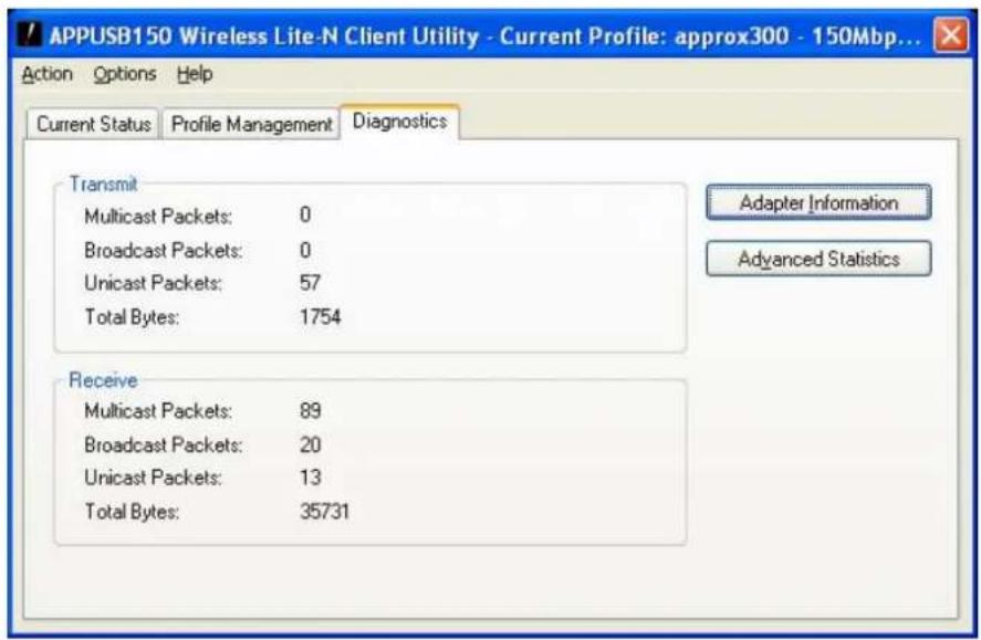
Figure 3-12
3.1.3.1. Check Driver Information
Click the Adapter Information button in the screen above, you will see the adapter information, including general information about the wire less network adapter and the Network Driver Interface Specification (NDIS) driver. Access the adapter information from the Diagnostics tab.
Card Name - The name of the wireless network adapter.
MAC Address - The MAC address of the wireless network adapter.
Driver - The driver name and path of the wireless network adapter driver.
Driver Version - The version of the wireless network adapter driver.
Driver Date - The creation date of the wireless network adapter driver.
- Client Name - The name of the client computer.
3.1.3.2. Check Receive and Transmit Statistical Information
The Advanced Statistics show receiving and transmitting statistical information about the following receiving and transmitting diagnostics for frames received by or transmitted to the wireless network adapter.
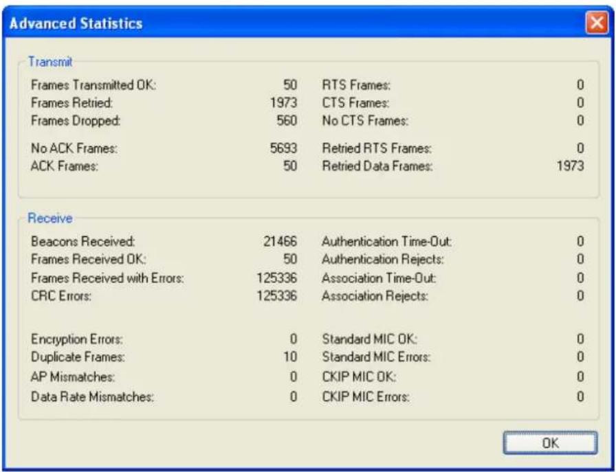
Figure 3-13
3.2 For Windows Vista
APPUSB150 Wireless Lite-N Client Utility (AWCU) is not available for Windows Vista. So after the Adapter's driver has been installed, we have to use Windows WLAN Autoconfig to establish a connection. Please follow the steps below.
- Right-click the icon 📋 at the bottom of your screen in your system tray and then select "Connect to a network".
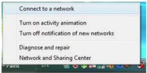
Figure 3-14
- This page will then display and you will see the available wireless network list. Select the SSID of your Access Point, take APPROX for example. Click Connect.
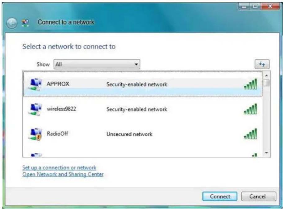
Figure 3-15 Select A Network
- Enter the passphrase, take 1234567890 for example. And then click Connect.

Figure 3-16 Enter Passphrase
- If the key entered is correct, you will successfully connect to the network.
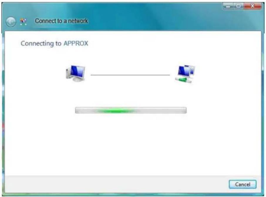
Figure 3-17 Connecting
- C lick Close to finish.
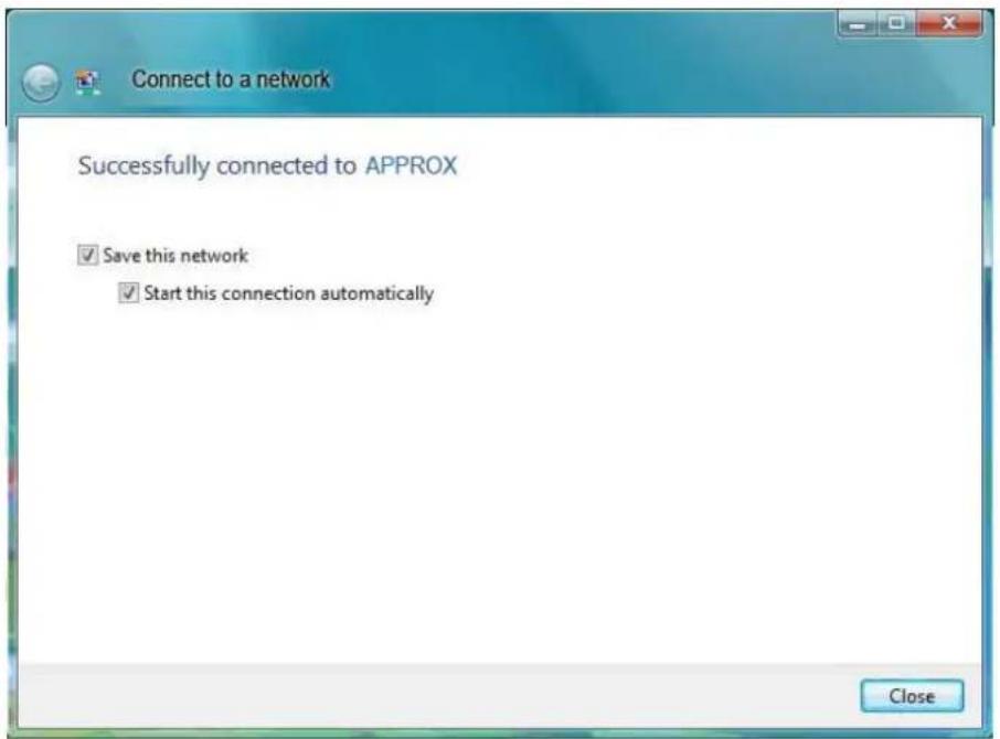
Figure 3-18 successfully Connected
3.3 For Windows 7
APPUSB150 Wireless Lite-N Client Utility (AWCU) is not available for Windows 7. So after the Adapter's driver has been installed, we have to use Windows WLAN Autoconfig to establish a connection. Please follow the steps below.
1. Right-click the icon

at the bottom of your screen in your system tray and then you will see ss network list. Select the SSID of your Access Point, take click Connect.
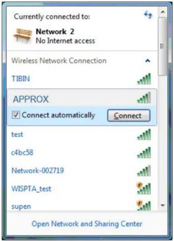
Figure 3-19 Select A Network
- If your wireless network is secured, you will be required to enter the security key as shown in Figure 3-20. Enter the passphrase, take 1234567890 for example. And then click OK.

Figure 3-20 Enter Passphrase
- If the key entered is correct, you will successfully connect to the network as shown in Figure 3-21.

Figure 3-21 Connecting
Chapter 4. WPS configuration
WPS (Wi-Fi Protected Setup) function allows you to add a new wireless device to an existing network quickly.
If the wirele ss card supports Wi-Fi Protected Setup (WPS), you can establish a w wireless connection between wir eless card and router using either Push Button C onfiguration (PBC) method or PIN method.
First, the WPS software should be in stalled. Insert the Resource CD into your CD-ROM drive. To continue, double-click My Computer, and the n double-click the CD/DVD drive w here the installation CD was placed. Open APPUSB150 folder, and double-click wps.exe. Then you will see Figure 4-1.
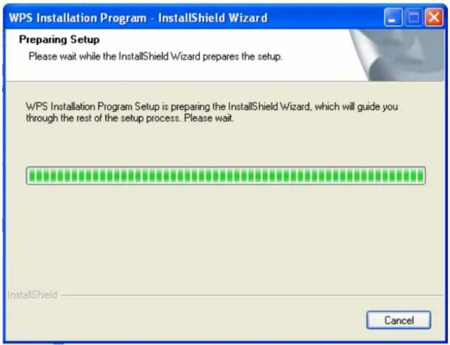
Figure 4-1
Then, please follow the step-by-step instruction to complete the WPS installation. After that, WPS function can be enabled. Here we will introduce two ways to configure the WPS.
4.1 PBC (Push Button Configuration) method
- Firstly, press the WPS button of the router. There are two ways:
1) Press the WPS button directly on the front panel of the Router shown in Figure 4-2.
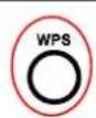
Figure 4-2
2) Open the Router's Web-based Utility and click WPS link on the left of the main menu. Then Figure 4-3 will appear. Click Add device, then you can see Figure 4-4. Select Press the button of the new device in two minutes and click Connect.
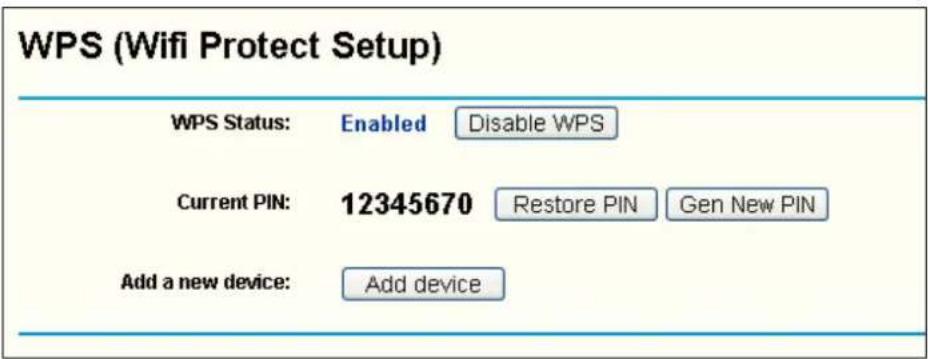
Figure 4-3
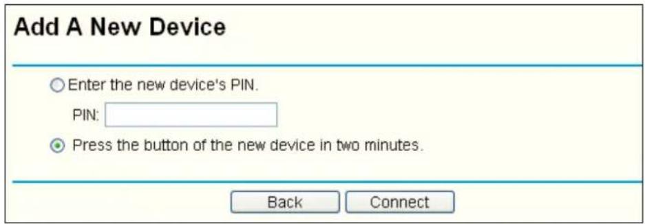
Figure 4-4
- Secondly, press the WPS button of the adapter. There are two ways:
1) Press and hold the WPS button of the adapter directly for 2 or 3 seconds.
2) Double click the icon 📋 on the desktop p to open the WPS Utility and then you can see the welcome screen shown as Figure 4-5. Click Next to continue. Then select Push the button on my access point in the next screen shown in Figure 4-6 and click Next.
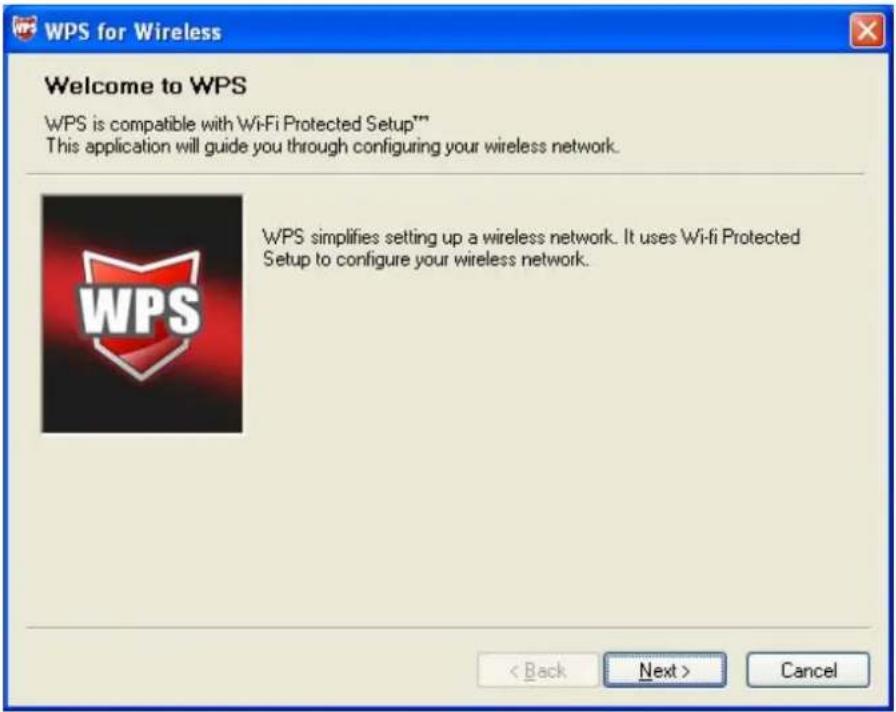
Figure 4-5
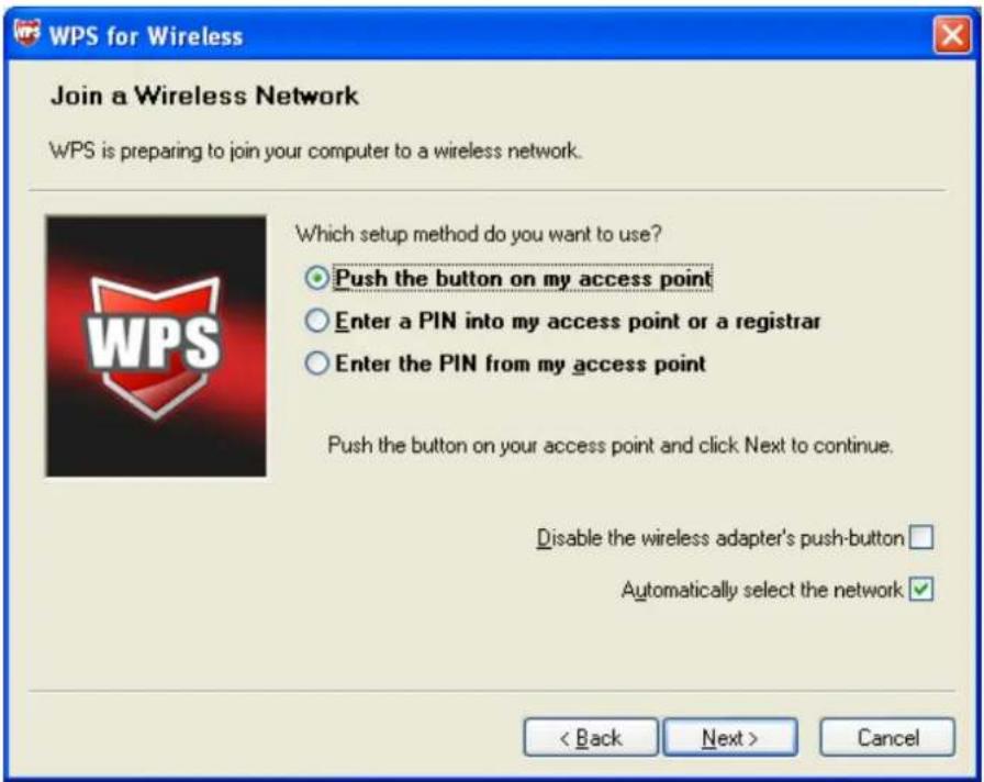
Figure 4-6
- Then wait a minute until Figure 4-7 appears. Click Finish to complete the W PS configuration.
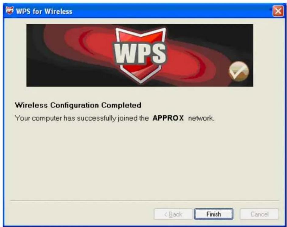
Figure 4-7
4.2 PIN method
There are two ways to configure the WPS by PIN method:
1) Enter a PIN into your AP device.
2) Enter the PIN from your AP device.
Following are the detailed configuration procedure of each way.
4.2.1 Enter a PIN into your AP device
- Double click the icon 📄 on the desktop to open the WPS Utility and then you can see the welcome screen shown as Figure 4-5 Click Next to continue. Figure 4-8 will appear. Select the second option, and you will see the PIN value of the adapter which h is randomly generated. Click Next.
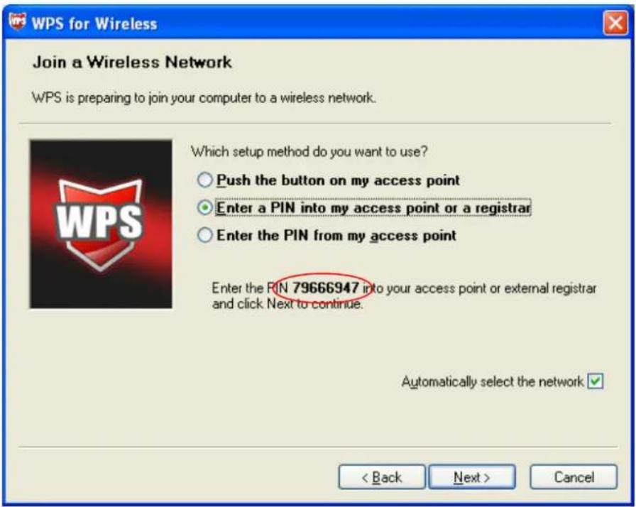
Figure 4-8
- Open the Router's Web-based Utility and click WPS link on the left of the main menu. Then Figure 4-3 will appear. Click Add device, then you can see Figure 4-8 Select Enter the new device's PIN and enter the PIN value of the adapter shown in Figure 4-8, click Connect.
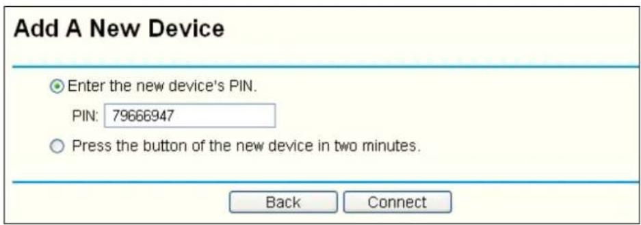
Figure 4-9
- When Figure 4-7 appears, the WPS configuration is complete.
4.2.2 Enter the PIN from your AP device
- Open the WPS Utility and you will see Figure 4-5. Click Next to continue. Then Figure 4-10 will appear. Select the third option and enter the PIN value which is labeled on the bottom of the Router. Click Next.
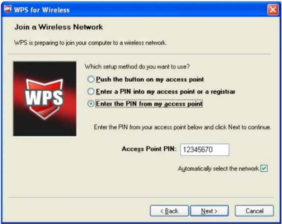
Figure 4-10
- When Figure 4-7 appears, the WPS configuration is complete.

Note:
If you generate a new PIN code for your Router, please enter the new one instead.
Appendix A: Specifications
| Normal | |
| Interface USB 2.0 Interface | |
| Standards | IEEE802.11g; IEEE802.11b; IEEE802.11n |
| Operating System Windows 2000/ Windows XP/ Windows Vista/ Windows 7 | |
| Radio Data Rate | 11b: 1/ 2/ 5.5/ 11 Mbps11g: 6/ 9/ 12/ 18/ 24/ 36/ 48/ 54 Mbps11n: up to 150 Mbps |
| Modulation | 11b:CCK,QPSK,BPSK;11g:OFDM; |
| Media Access Protocol CSMA/CA with ACK | |
| Data Security WPA/WPA2; 64/128-bit WEP; TKIP/AES | |
| Frequency 2.4 ~ 2.4835GHz | |
| Spread Spectrum Direct | Sequence Spread Spectrum (DSSS) |
| Safety & Emissions FCC, CE | |
| Environmental and Physical | |
| Operating Temp. 0°C~40°C (32°F~104°F) | |
| Storage Temp. -40°C–70°C (-40°F~158°F) | |
| Working Humidity 10% -90% RH, Non-condensing | |
| Storage Humidity 5% -90% RH, Non-condensing |
Appendix B: Glossary
802.11b - The 802.11b standard specifies a wireless product networking at 11 Mbps using direct-sequence spread-spectrum (DSSS) technology and operating in the unlicensed radio spectrum at 2.4GHz, and WEP encryption for security. 802.11b networks are also referred to as Wi-Fi networks.
802.11g - specification for wireless network ing at 54 Mbps using direct-sequence spread-spectrum (DSSS) technology, using O FDM modulation and operating in the unlicensed radio spectrum at 2.4GHz, and backward compatibility with IEEE 802.11b devices, and WEP encryption for security.
Ad-hoc Network - An ad-hoc network is a group of computers, each with a Wireless Adapter, connected as an independent 802.11 wireless LAN. Ad-hoc wireless computers operate on a peer-to-peer basis, communicating directly with each other without the use of an access point. Ad-hoc mode is also referred to as an I independent Basic Service Set (IBSS) or as peer-to-peer mode, and is useful at a departmental scale or SOHO operation.
DSSS - (Direct-Sequence Spread Spectrum) - DSSS generates a redundant bit pattern for all data transmitted. This bit pattern is called a chip (or chipping code). Even if one or more bits in the chip are damaged during transmission, statistical techniques embedded in the receiver can recover the original data without the need of retransmission. To an unintended receiver, DSSS appears as low power wi deband noise and is rejected (ignored) by most narrowband receivers. However, to an intended receiver (i.e. another wireless LAN endpoint), the DSSS signal is recognized as the only valid signal, and interference is inherently rejected (ignored).
FHSS - (Frequency Hopping Spread Spectrum) - FHSS continuously changes (hops) the carrier frequency of a conventional carrier several times per second according to a pseudo-random set of channels. Because a fixed frequency is not used, and only the transmitter and receiver know the hop patterns, interception of FHSS is extremely difficult.
Infrastructure Network - An infrastructure network is a group of computers or other devices, each with a Wireless Adapter, connected as an 802.11 wireless LAN. In infrastructure mode, the wireless devices communicate with each other and to a wired network by first going through an access point. An infrastructure wireless network connected to a wired network is referred to as a Basic Service Set (BSS). A set of two or more BSS in a single network is referred to as an Extended Service Set (ESS). Infrastructure mode is useful at a corporation scale, or when it is necessary to connect the wired and wireless networks.
Spread Spectrum - Spread Spectrum technology is a wideband radio frequency technique developed by the military for use in reliable, secure, mission-critical communications systems. It is designed to trade off bandwidth efficiency for reliability, integrity, and security. In other words, more bandwidth is consumed than in the case of narrowband transmission, but the trade off produces a signal that is, in effect, louder and thus easier to detect, provided that the receiver knows the parameters of the spread-spectrum signal being broadcast. If a receiver is not tuned to the right frequency, a spread-spectrum signal looks like background noise. There are two main alternatives, Direct Sequence Spread Spectrum (DSSS) and Frequency Hopping Spread Spectrum (FHSS).
SSID - A Service Set Identification is a thirty-two character (maximum) alphanumeric key identifying a wireless local area network. For the wireless devices in a network to communicate with each other, all devices must be configured with the same SSID. This is typically the configuration parameter for a wireless PC card. It corresponds to the ESSID in the wireless Access Point and to the wireless network name. See also Wireless Network Name and ESSID.
WEP - (Wired Equivalent Privacy) - A data privacy mechanism based on a 64-bit or 128-bit or 152-bit shared key algorithm, as described in the IEEE 802.11 standard. To gain access to a WEP network, you must know the key. The key is a string of characters that you create. When using WEP, you must determine the level of encryption. The type of encryption determines the key length h. 128-bit encryption requires a longer key than 64-bit encryption. Keys are defined by entering in a string in HEX (hexadecimal - using characters 0-9, A-F) or ASCII (American Standard Code for Information Interchange – alphanumeric characters) format. ASCII format is provided so you can enter a string that is easier to remember. The ASCII string is converted to HEX for use over the network. Four keys can be defined so that you can change keys easily.
Wi-Fi - A trade name for the 802.11b wireless networking standard, given by the Wireless Ethernet Compatibility Allianc e (WECA, see http://www.wi-f i.net), an industry standards group promoting interoperability among 802.11b devices.
WLAN - (Wireless Local Area Network) - A group of computers and associated devices communicate with each other wirelessly, which network serving users are limited in a local area.
WPA - (Wi-Fi Protected Access) - A wireless security protocol uses TKIP (Temporal Key Integrity Protocol) encryption, which can be used in conjunction with a RADIUS server.
DÉCLARATION FCC
FC
4. Configuration WPS
4.1 Méthode PBC (Push Button Configuration)
4.2 Méthode PIN
Figure 2-1
Figure 2-2
Figure 2-3
Figure 2-4
Figure 2-5
Figure 2-6
Figure 2-7
Remarque :
Figure 2-8
Figure 2-9
2.2.2 Pour Windows Vista
Figure 2-10
Figure 2-11
Figure 2-12
Remarque :
Figure 2-13
Figure 2-14
2.2.3 Pour Windows 7
Figure 2-15
Figure 2-16
Figure 2-17
Remarque :
Figure 2-18
Figure 2-19
3. Guide de configuration
3.1 Pour Windows XP
Figure 3-1
Figure 3-2
Figure 3-3
2. Modifier l'onglet Security
Figure 3-4
Figure 3-5
Remarque :
Figure 3-7
Figure 3-10
3.1.2.7 Auto Profile Selection Management
Figure 3-11
Figure 3-12
Figure 3-13
3.2 Pour Windows Vista
Figure 3-14
Figure 3-21
4 Configuration WPS
Figure 4-1
Figure 4-3
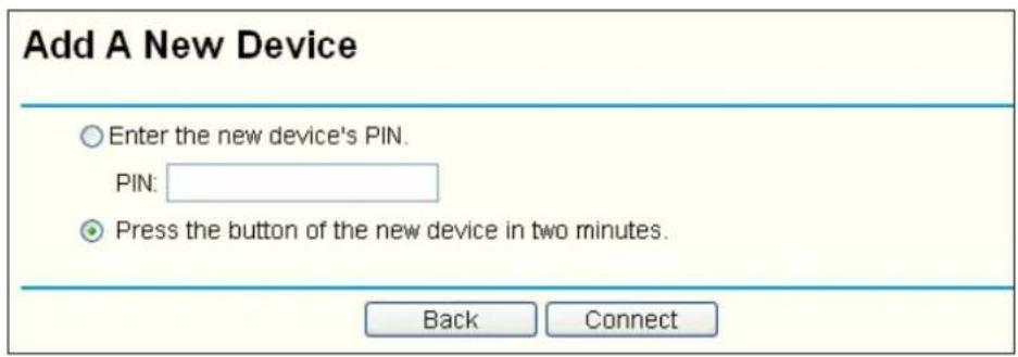
Figure 4-4
Figure 4-5
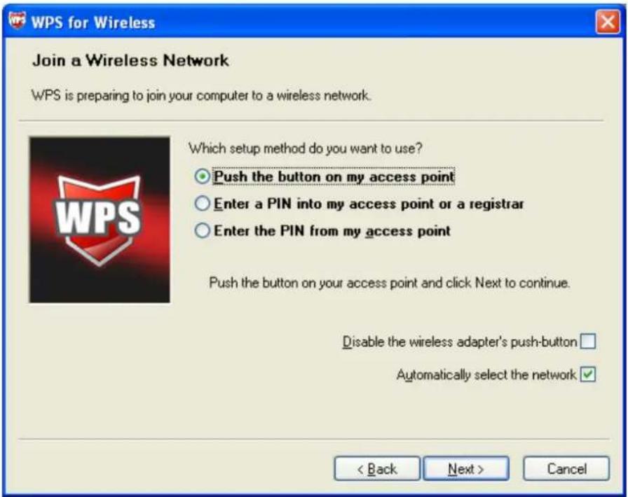
Figure 4-6
Figure 4-7
4.2 Méthode PIN
Figure 4-8
Figure 4-9
Figure 4-1
Bild 2-1
Bild 2-2
Bild 2-3
Bild 2-4
Bild 2-5
Bild 2-6
Bild 2-7
Hinweis:
Bild 2-8
Bild 2-9
Bild 2-10
Bild 2-11
Bild 2-12
Hinweis:
Bild 2-13
Bild 2-14
2.2.3 Für Windows 7
Bild 2-15
Bild 2-16
Bild 2-17
Hinweis:
Bild 2-18
Bild 2-19
Bild 3-1
▶ Add a new profile
Modify a profile
Remove a profile
Activate a Profile
Import a Profile
Export a Profile
➢ Scan Available Networks
Order profiles
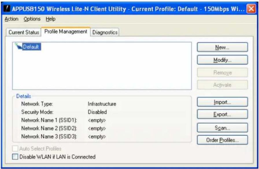
Bild 3-2
Bild 3-3
Bild 3-4
WPA/WPA2: Wi-Fi Protected Access
WPA/WPA2 Passphrase: Wi-Fi Protected Access Passphrase
802.1x: ermöglicht 802.1x Sicherheit
Bild 3-5
Hinweis:
Bild 3-7
Bild 3-10
3.1.2.7 Auto Profile Selection Management
Bild 3-11
Bild 3-12
Bild 3-13
Bild 3-14
Bild 3-17 Connecting
Bild 3-18 Successfully Connected
3.3 Für Windows 7
Bild 3-21 Verbunden
4 WPS Konfiguration
Bild 4-1
Bild 4-3
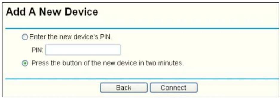
Bild 4-4
Bild 4-5

Bild 4-6
Bild 4-7
4.2 PIN Methode
Bild 4-8
Bild 4-9
Bild 4-10
Figura 2-1
Figura 2-2
Figura 2-3
Figura 2-4
Figura 2-5
Figura 2-6
Figura 2-7
Nb:
Figura 2-8
Figura 2-9
2.2.2 Per Windows Vista
Figura 2-10
Figura 2-11
Figura 2-12
Nota:
Figura 2-13
Figura 2-14
2.2.3 Per Windows 7
Figura 2-15
Figura 2-16
Figura 2-17

Nota:
Figura 2-18
Figura 2-19
Figura 3-1
Figura 3-2
Figura 3-3
Figura 3-4
Figura 3-5
Nb:
Figura 3-7
3.1.2.2 Rimuovere un profilo
Figura 3-10
3.1.2.7 Auto Profile Selection Management
Figura 3-11
Figura 3-12
Figura 3-13
3.2 Per Windows Vista
Figura 3-14
Figura 3-16 Inserire Passphrase
Figura 3-20 Inserire la Passphrase
Figura 4-1
Figura 4-3
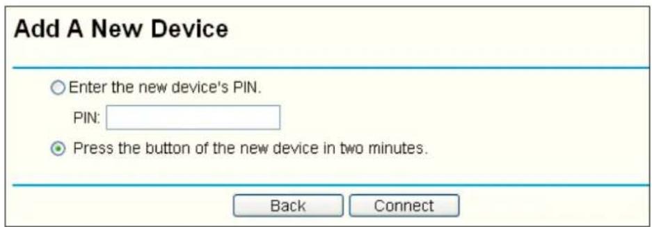
Figura 4-4
Figura 4-5

Figura 4-6
Figura 4-7
4.2 Modalità PIN
Figura 4-8
Figura 4-9
Figura 4-10
Figura 2-1
Figura 2-2
Figura 2-3
Figura 2-4
Figura 2-5
Figura 2-6
Figura 2-7
Nota:
Figura 2-8
Figura 2-9
2.2.2 Para Windows Vista
Figura 2-10
Figura 2-11
Figura 2-12
Nota:
Figura 2-13
Figura 2-14
2.2.3 Para Windows 7
Figura 2-15
Figura 2-16
Figura 2-17
Nota:
Figura 2-18
Figura 2-19
Figura 3-1
Figura 3-2
Figura 3-3
2. Editar o tab Security
Figura 3-4
3-5
Nota:
Figura 3-7
Figura 3-10
Figura 3-11
Figura 3-12
Figura 3-13
3.2 Para Windows Vista
Figura 3-14
Figura 3-17 Ligação
Figura 3-21 A Ligar
4 Configuração WPS
Figura 4-1
Figura 4-3
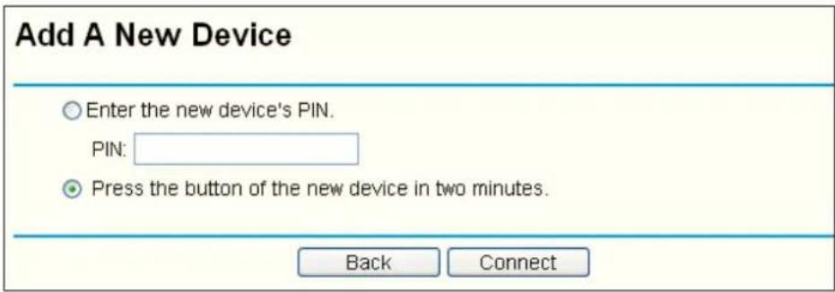
Figura 4-4
Figura 4-5
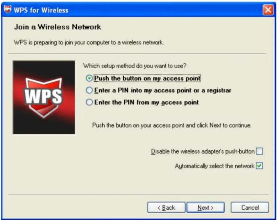
Figura 4-6
Figura 4-7
4.2 Método PIN
Figura 4-8
Figura 4-9
Figura 4-10


- Nota:
- Windows Vista
- Windows 7
- Note:
- Eliminar un perfil
- Auto Profile Selection Management
- Windows Vista
- Método PIN
- FCC RF Radiation Exposure Statement:
- CE Mark Warning
- National restrictions
- CONTENTS
- Package Contents
- Chapter 1. Introduction
- Chapter 2. Installation Guide
- Chapter 3. Configuration Guide
- Chapter 4. WPS configuration
- Appendix A: Specifications
- Appendix B: Glossary
- Overview of the product
- Features
- LED Status
- Hardware Installation
- Software Installation
- For Windows XP
- For Windows Vista
- For Windows 7
- For Windows XP
- Current Status
- Profile Management
- Add or Modify a Configuration Profile
- Edit the General tab
- Edit the Security tab
- Edit the Advanced tab
- Remove a profile
- Switch another Profile
- Export a Profile
- Import a Profile
- Scan Available Networks
- Auto Profile Selection Management
- Diagnostics
- Check Driver Information
- Check Receive and Transmit Statistical Information
- For Windows Vista
- For Windows 7
- Right-click the icon
- PBC (Push Button Configuration) method
- PIN method
- Enter a PIN into your AP device
- Enter the PIN from your AP device
- DÉCLARATION FCC
- FC
- Configuration WPS
- Remarque :
- Pour Windows Vista
- Pour Windows 7
- Guide de configuration
- Pour Windows XP
- Modifier l'onglet Security
- Pour Windows Vista
- Configuration WPS
- Méthode PIN
- Hinweis:
- Für Windows 7
- Für Windows 7
- WPS Konfiguration
- PIN Methode
- Nb:
- Per Windows Vista
- Per Windows 7
- Rimuovere un profilo
- Per Windows Vista
- Modalità PIN
- Para Windows Vista
- Para Windows 7
- Editar o tab Security
- Para Windows Vista
- Configuração WPS
Brand : Approx
Model : APPUSB150
Category : Network card / adapter