
RAS-M18YA-CVE - Air-conditioner TOSHIBA - Free user manual and instructions
Find the device manual for free RAS-M18YA-CVE TOSHIBA in PDF.

| Product type | Split air conditioner, cooling only |
| Brand | TOSHIBA |
| Model | RAS-M18YA-CVE |
| Refrigerant | R410A (HFC) |
| Power supply | 220-240 V ~ 50 Hz, single phase |
| Maximum operating current | 13.8 A |
| Recommended fuse | 15 A |
| Power cable cross-section | 2.0 mm² (AWG 14) or more |
| Connection cable cross-section | 1.0 mm² (AWG 18) or more |
| Liquid pipe | ø6.35 mm |
| Gas pipe | ø9.52 mm or ø12.7 mm |
| Copper pipe thickness | 0.8 mm |
| Maximum pipe length | 20 m per indoor unit |
| Maximum height difference | 10 m |
| Minimum pipe length | 2 m |
| Self-diagnosis | 5 red LEDs on inverter board |
| Protection | 30 mA residual current circuit breaker recommended |
| Specific R410A tools | Manometer, vacuum pump, torque wrench, HFC leak detector |
Frequently Asked Questions - RAS-M18YA-CVE TOSHIBA
User questions about RAS-M18YA-CVE TOSHIBA
0 question about this device. Answer the ones you know or ask your own.
Ask a new question about this device
Download the instructions for your Air-conditioner in PDF format for free! Find your manual RAS-M18YA-CVE - TOSHIBA and take your electronic device back in hand. On this page are published all the documents necessary for the use of your device. RAS-M18YA-CVE by TOSHIBA.
USER MANUAL RAS-M18YA-CVE TOSHIBA
AIR CONDITIONER (MULTI-SPLIT TYPE) OUTDOOR UNIT INSTALLATION MANUAL
TOSHIBA
Heat pump
RAS-M18YAV-E
Cooling only
RAS-M18YACV-E
RAS-3M23YACV-E
For general public use
Power supply cord of parts of appliance for outdoor use shall be more than polychloroprene sheathed flexible cord (design H05 RN-F), or cord designation 245 IEC 57.
UK PLUGS AND SOCKETS ETC (SAFETY) REGULATIONS 1994, SI NUMBER 1768
With regard to Schedule 3, item 7 of the above UK Regulations, this appliance must be permanently connected to the fixed wiring of the main electrical supply by means other than the use of an approved 13 Amp plug-top as outlined in the Regulations.
Electrical work must be carried by suitably qualified persons and in accordance with all relevant safety standards and codes of practice.
We recommend that the power supply for this appliance is derived from a suitably protected dedicated circuit.
(for U.K. only)
CAUTION
New Refrigerant Air Conditioner Installation
- THIS AIR CONDITIONER ADOPTS THE NEW HFC REFRIGERANT (R410A) WHICH DOES NOT DESTROY OZONE LAYER.
R410A refrigerant is apt to be affected by impurity such as water, oxidizing membrane, and oils because pressure of R410A refrigerant is approx. 1,6 times of refrigerant R22. Accompanied with adoption of the new refrigerant, refrigerating machine oil has been also changed. Therefore, during installation work, be sure that water, dust, former refrigerant, or refrigerating machine oil does not enter into the refrigerating cycle of new-refrigerant air conditioner.
To prevent mixing of refrigerant or refrigerating machine oil, the sizes of connecting sections of charging port of the main unit or installation tools are different from those for the conventional refrigerant. Accordingly, the exclusive tools are required for the new refrigerant (R410A) as shown below.
For connecting pipes, use new and clean piping materials with high pressure-tight force, which were made for R410A only, so that water or dust does not enter. Moreover, do not use the existing piping because there are problems about pressure-tight force and inner impurity in the existing piping.
CAUTION
To Disconnect the Appliance from the Mains Supply.
This appliance must be connected to the mains by means of a circuit breaker or a switch with a contact separation of at least 3 mm.
DANGER
Engage Dealer or Specialist for Installation.
- FOR ELECTRICAL WORKS THE WIRING AND CABLES MUST BE PERFORMED IN COMPLIANCE WITH NATIONAL WIRING STANDARD OR REGULATION.
IF INCORRECT AND INCOMPLETE WIRING IS CARRIED OUT, IT WILL CAUSE AN ELECTRICAL FIRE OR ELECTRICAL SHOCK.
- USE THE SPECIFIED CABLE (1,0mm ^2 or more) AND CONNECT TIGHTLY FOR INDOOR/OUTDOOR CONNECTION. CONNECT TIGHTLY AND CLAMP THE CABLE SO THAT EXTERNAL FORCE WILL BE ACTED ON THE TERMINAL.
- WIRE ROUTING MUST BE PROPERLY ARRANGED SO THAT CONTROL BOARD COVER IS FIXED PROPERLY.
• DO NOT DAMAGE OR SCRATCH THE CONDUCTIVE CORE AND INNER INSULATOR OF THE CABLES. - DO NOT DEFORM OR SMASH ON THE SURFACE OF THE CABLES. DO NOT PRESS OR FIX THE CORD AND CABLES FIRMLY WITH STAPLES, etc.
- DO NOT USE THE INTER-CONNECTING CABLE. NEVER EXECUTE THE CONNECTION OF WIRING WITH OTHER METHOD THAN THE APPROVED ONE. OTHERWISE, OVERHEAT, SMOKE OR FIRE MAY BE GENERATED BY CONTACT ERROR.
- TURN OFF MAIN POWER SUPPLY AND BREAKER BEFORE ATTEMPTING ANY ELECTRICAL WORK. MAKE SURE ALL POWER SWITCHES AND BREAKER TURN OFF. FAILURE TO DO SO MAY CAUSE ELECTRIC SHOCK.

- CONNECT THE CONNECTING CABLE CORRECTLY. IF THE CONNECTING CABLE IS CONNECTED BY WRONG WAY, ELECTRIC PARTS MAY BE DAMAGED.
• GROUNDING WIRE WORKS MUST BE CONSTRUCTED IN COMPLIANCE WITH INSTALLATION MANUAL. - BE SURE TO USE THE CORD-CLAMPS AND THE UNIT COVER TO THE SPECIFIED POSITIONS WITH ATTACHED TO THE PRODUCT. MOUNT THE UNIT COVER FOR CABLES OF CONNECTING SECTION FIRMLY WITH THE SCREWS.
- DO NOT INSTALL NEAR CONCENTRATIONS OF COMBUSTIBLE GAS OF GAS VAPORS. FAILURE TO FOLLOW THIS INSTRUCTION CAN RESULT IN FIRE OR EXPLOSION.
- IF A REFRIGERATION GAS LEAKS DURING INSTALLATION, BE SURE TO PERFORM VENTILATION. IF THE REFRIGERANT GAS COMES INTO CONTACT WITH FIRE, A POISONOUS GAS MAY OCCUR. WHEN INSTALLING AN AIR CONDITIONER, DO NOT ALLOW AIR OR MOISTURE TO REMAIN IN THE RE-FRIGERATION CYCLE. OTHERWISE, PRESSURE IN THE REFRIGERATION CYCLE MAY BECOME ABNORMALLY HIGH SO THAT A RUPTURE OR PERSONAL INJURY MAY BE CAUSED.
WARNING
- Never modify this unit by removing any of the safety guards of by-passing any of the safety interlock switches.
- Do not install in a place which cannot bear the weight of the unit.
Personal injury and property damage can result if the unit falls.
- Before doing the electrical work, attach an approved cable to the power supply cord.
And make sure the equipment to be earthed.
- For installation, use the tools and piping materials exclusively manufactured for R410A, and install securely in compliance with this Installation Manual.
Pressure of the used HFC R410A refrigerant becomes higher approx. 1,6 times of that of the conventional refrigerant. Therefore, if the exclusive piping materials are not used or incomplete installation is carried out, it may cause a rupture or personal injury, as well water leak, electrical shock, and a fire may be caused.
- When installing or moving the air conditioner, do not mix air and so on than the specified refrigerant (R410A) in the refrigeration cycle. If air and so on is mixed, the pressure in the refrigeration cycle may become abnormally high so that personal injury may be caused by a rupture.
CAUTION
- Exposure of unit or water or other moisture before installation will result in an electrical short. Do not store in a wet basement or expose to rain or water.
• After unpacking the unit, examine it carefully for possible damage. - Do not install in a place that can increase the vibration of the unit. Do not install in a place that can amplify the noise level of the unit or where noise and discharged air might disturb user's neighbors.
- To avoid personal injury, be careful when handling parts with sharp edges.
- Please read the installation manual carefully before installing the unit. It contains further important instructions for proper installation.
- Never install a power capacitor for power factor improvement.
Required tools for installation work
1) Philips screw driver
2) Hole core drill (65 mm)
3) Spanner
4) Pipe cutter
5) Knife
6) Reamer
7) Gas leak detector
8) Tape measure
R410A (Special requirement)
17) Gauge manifold
(Charge hose : R410A special requirement)
18) Vacuum pump
(Charge hose : R410A special requirement)
19) Torque wrench
1/4 (17 mm) 16N•m (1,6 kgf•m)
3/8 (22 mm) 42N•m (4,2 kgf•m)
1/2 (26 mm) 55N•m (5,5 kgf•m)
20) Copper pipe gauge adjusting projection margin
21) Vacuum pump adapter
Accessory and Installation Parts
①

Owner's manual x 1
②
Outdoor unit installation manual x 3
③
Specifications x 1
④
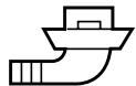
Drain nipple x 1 (Heat pump model only)
①
③
Refrigerant Piping
- Piping kit used for the conventional refrigerant cannot be used.
- Use copper pipe with 0,8 mm or more thickness.
- Flare nut and flare works
- Flare nut and flare works are also different from those of the conventional refrigerant. Take out the flare nut attached to the main unit of the air conditioner, and use it.
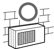
Installation Place
- A place which provides the spaces around the outdoor unit.
- A place where the operation noise and discharged air do not disturb your neighbors.
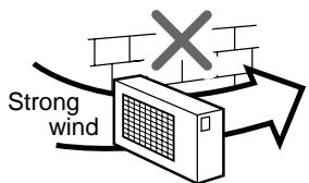
- A place which is not exposed to a strong wind.
- A place which does not block a passage.
- When the outdoor unit is to be installed in an elevated position, be sure to secure its feet.
- There must be sufficient spaces for carrying the unit into and out of the site.
- A place where the drain water does not raise any problem.
CAUTION
- Install the outdoor unit without anything blocking the air discharging.
- When the outdoor unit is installed in a place exposed always to a strong wind like a coast or on a high story of a building, secure the normal fan operation using a duct or a wind shield.
- Specially in windy area, install the unit to prevent the admission of wind.
- Installation in the following places may result in trouble. Do not install the unit in such places.
- A place full of machine oil.
• A place full of sulfide gas.
- A place where high-frequency waves are likely to be generated as from audio equipment, welders, and medical equipment.
Optional Installation Parts (Local Supply)
| Parts name | Q'ty | |
| A | Refrigerant pipingLiquid side : ø6,35 mmGas side : ø9,52 mm or ø12,7 mm | Each one |
| B | Pipe insulating material(polyethylene foam, 6 mm thick) | 1 |
| C | Putty, PVC tapes | Each one |
Optional Installation Parts (Separate Sold)
| Parts name | |
| RB-M43RE | Reducer ( 12,7 9,52 ) |
| RB-M34EE | Expander ( 9,52 12,7 ) |
Refrigerant Piping Connection
CAUTION
KEEP IMPORTANT 4 POINTS FOR PIPING WORK
- Take away dust and moisture.
(Inside of the connecting pipes) - Tight connection (between pipes and unit)
- Evacuate the air in the connecting pipes using VACUUM PUMP.
- Check gas leak. (connected points)
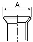
Flaring
- Cut the pipe with a pipe cutter.
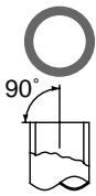

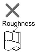
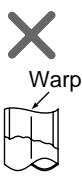
- Insert a flare nut into the pipe, and flare the pipe.
As the flaring sizes of R410A differ from those of refrigerant R22, the flare tools newly manufactured for R410A are recommended.
However, the conventional tools can be used by adjusting projection margin of the copper pipe.
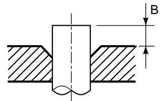
- Projection margin in flaring : B (Unit : mm)
Rigid (Clutch type)
| Outer dia. of copper pipe | R410A tool used | Conventional tool used | ||
| R410A | R22 | R410A | R22 | |
| 6,35 | 0 ~ 0,5 | (Same as left) | 1,0 ~ 1,5 | 0,5 ~ 1,0 |
| 9,52 | 0 ~ 0,5 | (Same as left) | 1,0 ~ 1,5 | 0,5 ~ 1,0 |
| 12,7 | 0 ~ 0,5 | (Same as left) | 1,0 ~ 1,5 | 0,5 ~ 1,0 |
Imperial (Wing nut type)
* In the case of flaring for R410A with the conventional flare tool, pull out it approx. 0,5 mm more than that for R22 to adjust to the specified flare size. The copper pipe gauge is useful for adjusting projection margin size.
Installation
NOTE : For installation, at least 3 dimensions should be kept free from obstacles (walls).
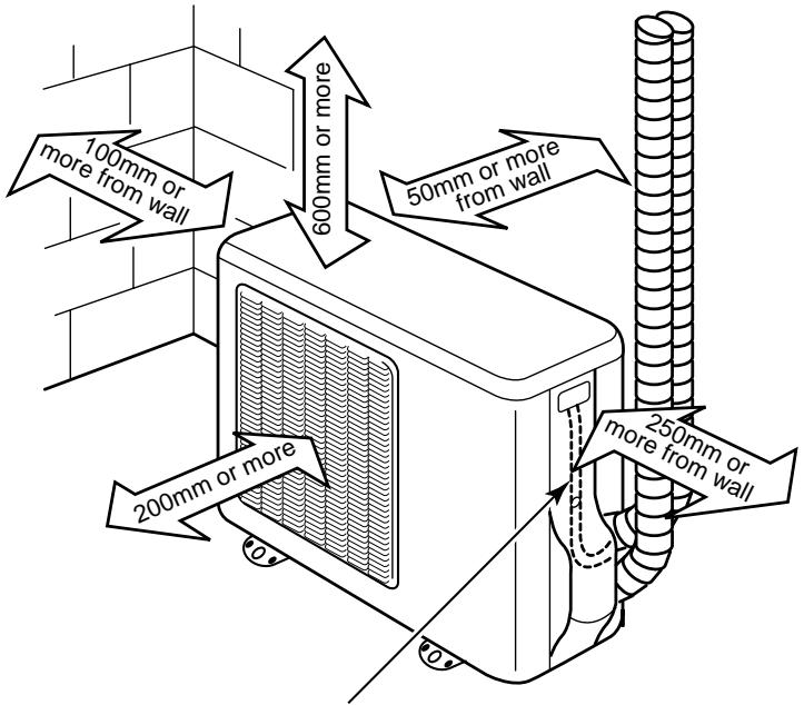
As shown in the figure, hang power cord and connecting cable downward, and take out it along piping connection port.
Fixing bolt arrangement of outdoor unit
- Secure the outdoor unit with the fixing bolts and nuts if the unit is likely to be exposed to a strong wind.
- Use 8 mm or 10 mm anchor bolts and nuts.
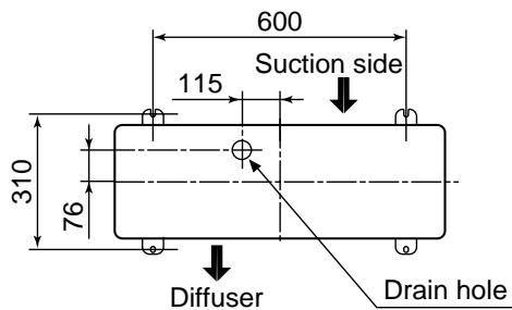
- If it is necessary to drain the defrost water attach drain nipple to the bottom plate of the outdoor unit before installing it.
Drainage
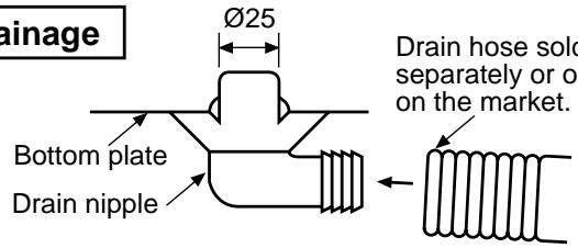
- Install the provided drain nipple in the hole of the bottom plate.
- Perform proper drainage processing using a drain hose sold separately or one on the market. (Inner diameter : 16 mm)
-
Do not use an ordinary hose on the market, because it tends to get flat and as a result, it prevents water from draining.
-
Piping connections to the outdoor unit should be arranged in the sequence A, B, C, starting from the bottom.
(For each piping connection, the gas pipe is on the bottom and the liquid pipe is on the top.) -
When multiple indoor units are to be connected to the outdoor unit, make the ends of the pipes and wires from each indoor unit to ensure that they will be connected to the outdoor unit correctly. (Problems caused by indoor units being connected to the outdoor unit incorrectly are very common in multiple-unit installations.)
-
The length and height difference of the connecting pipes between the indoor and outdoor units must be within the ranges indicated below.
• Total piping length : Two room (A + B) Multi, Non. Additional refrigerant Three room (A + B + C) Multi, Non. Additional refrigerant
- Minimum piping length: A or B or C = 2 m or more (A or B = 7 m or more for one unit for heat pump)
• Maximum indoor piping length : A or B or C = 20 m or less
• Maximum piping height difference : A or B or C = 10 m or less
• Maximum piping / height difference between two rooms = 10 m or less
-
If the outdoor unit is to be mounted on a wall, make sure that the platform supporting it is sufficiently strong. The platform should be designed and manufactured maintain its strength over a long period of time, and sufficient consideration should be given to ensuring that the outdoor unit will not fall.
-
When the outdoor unit is to be mounted high on a wall, take particular care to ensure that parts do not fall installer is protected.
-
When doing installation work on level ground, it is usual to wiring and piping connections to the indoor units. And/then make to the outdoor unit.
However if outdoor work is difficult it is possible instead to make changes to the procedure.
For example by making adjustments to the wiring and piping length on the inside (rather than the outside).
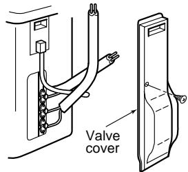
How to remove the valve cover
- Remove a screw of the valve cover.
- Pull the valve cover downward.
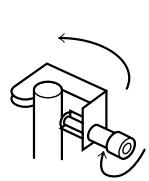
Tightening connection
Align the centers of the connecting pipes and tighten the flare nut as far as possible with your fingers. Then tighten the nut with a spanner and torque wrench as shown in the figure.
CAUTION
- Do not apply excess torque. Otherwise, the nut may crack depending on the conditions.
(Unit : N·m)
| Outer dia. of copper pipe | Tightening torque |
| ø6,35 mm | 14 ~18 (1,4 ~ 1,8 kgf•m) |
| ø9,52 mm | 33 ~42 (3,3 ~ 4,2 kgf•m) |
| ø12,7 mm | 50 ~62 (5,0 ~ 6,2 kgf•m) |
- Tightening torque of flare pipe connections
Pressure of R410A becomes higher than that of R22. (Approx. 1,6 times) Therefore, using a torque wrench, tighten firmly the flare pipe connecting sections which connect the indoor and outdoor units up to the specified tightening torque. Incorrect connections may cause not only a gas leakage, but also a trouble of the refrigeration cycle.
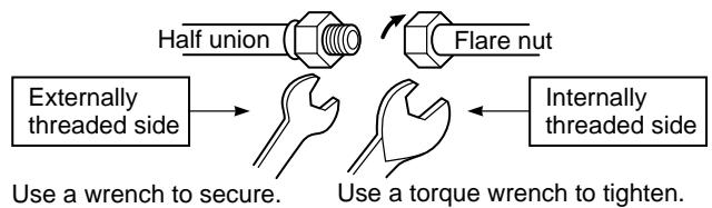
flowchart
graph LR
    A["Flare nut"] --> B["Half union"]
    B --> C["Externally threaded side"]
    C --> D["Use a wrench to secure."]
    D --> E["Use a torque wrench to tighten."]
    E --> F["Internally threaded side"]
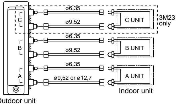
| Connectable capacity class | ||||
| A | B | C | Total | |
| M18 | 10, 13 | 10, 13 | — | 23 |
| 3M23 | 10, 13(with reducer) | 16(with expander) | 16(with expander) | 36 |
| 16 | 10, 13 | 10, 13 | ||
Evacuating
After the piping has been connected to all indoor unit(s), you can perform the air purge together at once.
AIR PURGE
Evacuate the air in the connecting pipes and in the indoor unit using vacuum pump.
Do not use the refrigerant in the outdoor unit.
For details, see the manual of vacuum pump.
Use a vacuum pump
Be sure to use a vacuum pump with counter-flow prevention function so that inside oil of the pump does not flow backward into pipes of the air conditioner when the pump stops. (If inside oil of the vacuum pump enters into the air conditioner which adopts R410A, a trouble of the refrigeration cycle may be caused.)
- Connect the charge hose from the manifold valve to the service port of the gas side packed valve.
- Connect the charge hose to the port of vacuum pump.
- Open fully the low pressure side handle of the gauge manifold valve.
- Operate the vacuum pump to start for evacuating. Perform evacuating for about 15 minutes if the piping length is 20 meters. (15 minutes for 20 meters) (assuming a pump capacity of 27 liters per minute.)
Then confirm that the compound pressure gauge reading is -101 kPa (-76 cmHg).
- Close the low pressure side valve handle of gauge manifold.
- Open fully the valve stem of the packed valves (both side of Gas and Liquid).
- Remove the charging hose from the service port.
- Securely tighten the caps on the packed valves.
- Execute above works from 1 to 8 on the each connected indoor unit.

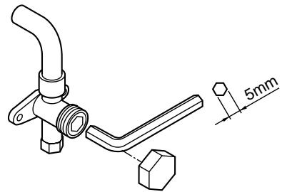
Packed valve handling precautions
- Open the valve stem all the way out; so not try to open it beyond the stopper.
- Securely tighten the valve stem cap torque is as follows :
| Gas side (ø12,7 mm) | 50 ~ 62 N•m (5,0 ~ 6,2 kgf•m) |
| Gas side (ø9,52 mm) | 33 ~ 42 N•m (3,3 ~ 4,2 kgf•m) |
| Liquid side (ø6,35 mm) | 14 ~ 18 N•m (1,4 ~ 1,8 kgf•m) |
| Service port | 14 ~ 18 N•m (1,4 ~ 1,8 kgf•m) |
Hexagonal wrench is required.
Electrical Work
For the air conditioner that has no power cord, connect a power cord to it as mentioned below.
| Model | Two room Multi | Three room Multi | |
| RAS-M18YAV-E | RAS-M18YACV-E | RAS-3M23YACV-E | |
| Power source | 220 – 240 VSingle phase 50 Hz | ||
| Maximum running current | 13,8 A | 11,9 A | 11 A |
| Fuse rating | 15 A | 15 A | 15 A |
| Power cord | 2,0 mm ^2 (AWG-14) or more | ||
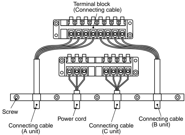
How to wiring connection
- Connect the connecting cable to the terminal as identified with their respective matched numbers on the terminal block of indoor and outdoor unit. (1,0 mm ^2 AWG 18 or more)
- When connecting the connecting cable to the outdoor unit terminal, prevent water coming in the outdoor unit.
- Insulate the unused cords (conductors) with strip the sheath of connecting cable with PVC tape.
Process them so that they do not touch any electrical or metal parts. - For inter-unit wiring, do not use a cut wire jointed to another on the way.
Use wires long enough to cover the entire length.
Two room (A + B) Multi
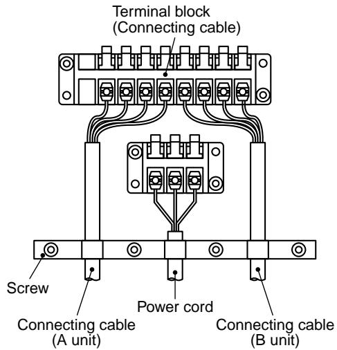
Three room (A + B + C) Multi
CAUTION
- Wrong wiring connection may cause some electrical parts burn out.
- Be sure to use the cord clamps specified positions with attached to the product.
- Do not damage or scratch the conductive core and inner insulator of power and inter-connecting cables when peeling them.
- Be sure to comply with local codes on running the wire from outdoor unit to indoor unit (size of wire and wiring method etc.)
- Use the power cord and Inter-connecting cable with specified thickness, specified type, and protective devices specified.
Stripping length power cord and connecting cable

Check and Test Operation
For R410A, use the leak detector exclusively manufactured for HFC refrigerant (R410A, R134a, etc.).
* The conventional leak detector for HCFC refrigerant (R22, etc.) cannot be used because its sensitivity for HFC refrigerant lowers to approx. 1/40.
- Pressure of R410A becomes approx. 1,6 times of that of R22. If installation work was incompletely finished, a gas leakage may occur in the cases such as pressure rise during operation. Therefore, be sure to test the piping connections for leaking.
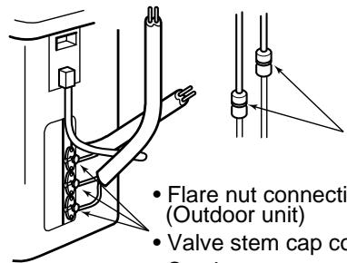
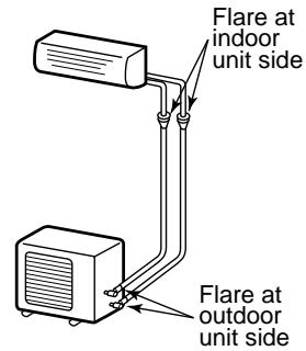
Flare nut connections (Indoor unit)
- Flare nut connections
(Outdoor unit) - Valve stem cap connection
• Service port cap connection
MISWIRING (MISPIPING) CHECK
Make sure that the wiring and piping for each room have the same alphabetical code (A, B, C).
Connect and secure the power cord.
Use the power cord / cables with thickness, type, and protective devices specified in this manual.
Insulate the unused cords (conductors) with PVC tape.
- Turn on the electrical power breaker.
Useful Functions
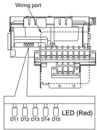
- For this outdoor unit, the self-diagnosis is possible by using five LEDs (Red).
* LEDs (Red) (D11 to D15) locate on the sub-control board underneath of the inverter.
| LED indication | Indoor alarm code | Contents | ||||
| D11 | D12 | D13 | D14 | D15 | ||
| ● | ● | ● | ● | ● | None | Normal running |
| α | ● | ● | ● | ● | 07 | Compressor thermo. operation, Instantaneous power failure, Gas leakage |
| ● | α | ● | ● | ● | 14 | G-Tr short circuit, Compressor motor rear short |
| α | α | ● | ● | ● | 16 | Trouble on position detecting circuit |
| ● | ● | α | ● | ● | 17 | Trouble on current detecting circuit |
| α | ● | α | α | ● | 18 | Outdoor heat exchanger temp. sensor (TE) fault |
| ● | ● | α | α | ● | 18 | Suction temp. sensor (TS) fault |
| ● | α | α | ● | ● | 19 | Delivery temp. sensor (TD) fault |
| α | α | α | ● | ● | 1A | Trouble on outdoor fan |
| ● | ● | ● | α | ● | 1B | Outer temp. sensor (TO) fault |
| α | ● | α | ● | ● | 1C | Trouble on compressor system |
| α | α | α | α | ● | 1C | Temp. sensor (TGa) fault at A room gas side |
| α | ● | ● | ● | α | 1C | Temp. sensor (TGb) fault at B room gas side |
| α | α | ● | ● | α | 1C | Temp. sensor (TGc) fault at C room gas side |
| ● | α | α | ● | α | — | Gas leakage, TS sensor out of place, PMV, sensor fault |
| α | α | α | ● | α | — | TE sensor out of place, Indoor heat exchanger sensor (TC) out of place, PMV, sensor fault |
| ● | ● | ● | α | α | 1C | Miswiring at indoor or outdoor, Gas leakage, TS, TC sensor out of place, PMV, sensor fault |
| α | ● | ● | α | α | 1C | TGa sensor out of place, PMV, sensor fault |
| α | α | ● | α | α | 1C | Communication trouble between MCU |
| α | ● | ● | α | ● | 1D | Compressor lock |
| ● | α | ● | α | ● | 1E | Trouble on delivery temp, Gas leakage |
| α | α | ● | α | ● | 1F | Compressor break down |
- Check the flare nut connections, valve stem cap connections and service port cap connections for gas leak with a leak detector or soap water.
CAUTION
- Use a circuit breaker of a type that is not tripped by shock waves.
- If incorrect/incomplete wiring is carried out, it will cause an electrical fire or smoke.
- Prepare the power source for exclusive use with the air conditioner.
- This product can be connected to the mains. Connection to fixed wiring :
A switch or circuit breaker which disconnects all poles and has a contact separation of at least 3 mm must be incorporate in the fixed wiring.
An approved short circuit breaker or switches must be used.
* (A breaker having a sensitivity of approximately 0,1 second or less and a capacity of approximately 30 mA is usually used.)
-
Operate the indoor unit with cooling mode.
-
Start the check.
-
Run the indoor unit in A room, and confirm cool air blows out.
- Confirm the indoor unit in B, C room does not run. (In this time, also check flowing sound of refrigerant is not heard.)
- Stop operation of the indoor unit in A room, and execute the same checks on the indoor unit in B, C room.
Self-Diagnosis by LED Indication
- If a trouble occurs, LED (Red) goes on according to the contents of trouble as shown in the left table.
- When two or more troubles occur, LEDs go on cyclically (alternately).
- Usually, LEDs (Red) go off.
Installation/Servicing Tools
Changes in the product and components
In the case of an air conditioner using R410A, in order to prevent any other refrigerant from being charged accidentally, to service port diameter of the outdoor unit control valve (3 way valve) has been changed. (1/2 UNF 20 threads per inch)
- In order to increase the pressure resisting strength of the refrigerant piping flare processing diameter and size of opposite side of flare nuts has been changed. (for copper pipes with nominal dimensions 1/2 and 5/8)
New tools for R410A
| New tools for R410A | Applicable to R22 model | Changes | |
| Gauge manifold | × |  | As pressure is high, it is impossible to measure by means of conventional gauge. In order to prevent any other refrigerant from being charged, each port diameter has been changed. |
| Charge hose | × | 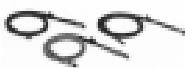 | In order to increase pressure resisting strength, hose materials and port size have been changed (to 1/2 UNF 20 threads per inch). When purchasing a charge hose, be sure to confirm the port size. |
| Electronic balance for refrigerant charging | ○ |  | As pressure is high and gasification speed is fast, it is difficult to read the indicated value by means of charging cylinder, as air bubbles occur. |
| Torque wrench (nominal diam. 1/2, 5/8) | × |  | The size of opposite sides of flare nuts have been increased. Incidentally, a common wrench is used for nominal diameters 1/4 and 3/8. |
| Flare tool (clutch type) | ○ |  | By increasing the clamp bar's receiving hole, strength of spring in the tool has been improved. |
| Gauge for projection adjustment | — | Used when flare is made by using conventional flare tool. | |
| Vacuum pump adapter | ○ | 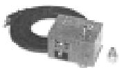 | Connected to conventional vacuum pump. It is necessary to use an adapter to prevent vacuum pump oil from flowing back to the charge hose. The charge hose connecting part has two ports-one for conventional refrigerant (7/16 UNF 20 threads per inch) and one for R410A. If the vacuum pump oil (mineral) mixes with R410A a sludge may occur and damage the equipment. |
| Gas leakage detector | × | 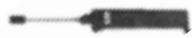 | Exclusive for HFC refrigerant. |
- Incidentally, the “refrigerant cylinder” comes with the refrigerant designation (R410A) and protector coating in the U. S's ARI specified rose color (ARI color code: PMS 507).
- Also, the “charge port and packing for refrigerant cylinder” require 1/2 UNF 20 threads per inch corresponding to the charge hose’s port size.
CLIMATISEUR (TYPE "MULTI-FENTES") INSTRUCTIONS POUR L'INSTALLATION DE L'UNITE D'EXTERIEUR Racco à chaleur
TOSHIBA
Pompe à chaleur
RAS-M18YAV-E
natural_image
Technical line drawing of a mechanical assembly with no visible text or symbols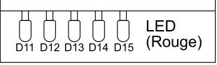
✗ : LED ON ● : LED OFF
KLIMAGERÄT (MULTI-SPLIT TYP) INSTALLATIONSHANDBUCH AUSSENGERÄT
TOSHIBA
Wärmepumpe
RAS-M18YAV-E
Nur Kühlung
RAS-M18YACV-E RAS-3M23YACV-E

Zum allgemeinen