
RAS-10YA-HX - Air conditioner TOSHIBA - Free user manual and instructions
Find the device manual for free RAS-10YA-HX TOSHIBA in PDF.

| Product Type | Split air conditioner (cooling only) |
| Indoor Model | RAS-10YK-HX |
| Outdoor Model | RAS-10YA-HX |
| Cooling Capacity | 2.70 kW (220–240 V) |
| Power Consumption | 0.80–0.85 kW |
| Power Supply | 220–240 V, 50 Hz, single phase |
| Indoor Unit Dimensions (H × W × D) | 265 × 790 × 189 mm |
| Indoor Unit Net Weight | 8 kg |
| Outdoor Unit Dimensions (H × W × D) | 530 × 770 × 200 mm |
| Outdoor Unit Net Weight | 29 kg |
| Refrigerant | R-22 (0.70 kg) |
| Indoor Fan Motor Output | 20 W |
| Outdoor Fan Motor Output | 18 W |
| Compressor Output | 750 W (model 2PS146D5AB02) |
| Indoor Noise Level (H/M/L) | 44 / 36 / 29 dB(A) |
| Outdoor Noise Level | 44–45 dB(A) |
| Airflow Rate (High/Med/Low) | 650 / 510 / 430 m³/h |
| Pipe Connection (Gas) | 9.52 mm (flare) |
| Pipe Connection (Liquid) | 6.35 mm (flare) |
| Maximum Pipe Length | 10 m |
| Maximum Height Difference | 5 m |
| Drain Pipe Outer Diameter | 16 mm |
| Air Filter | Washable polypropylene net |
| Auto Louver | Yes |
| Safety Devices | Fuse, overload relay |
| Usable Outdoor Temperature | 21–43 °C |
Frequently Asked Questions - RAS-10YA-HX TOSHIBA
User questions about RAS-10YA-HX TOSHIBA
0 question about this device. Answer the ones you know or ask your own.
Ask a new question about this device
Download the instructions for your Air conditioner in PDF format for free! Find your manual RAS-10YA-HX - TOSHIBA and take your electronic device back in hand. On this page are published all the documents necessary for the use of your device. RAS-10YA-HX by TOSHIBA.
USER MANUAL RAS-10YA-HX TOSHIBA
natural_image
Line drawing of a TOSHIBA air conditioner unit with attached remote control and fan (no text or symbols)CONTENTS
- SPECIFICATIONS.... 3
- CONSTRUCTION VIEWS .... 8
- WIRING DIAGRAM 10
- SPECIFICATIONS OF ELECTRICAL PARTS ...... 11
- REFRIGERANT CYCLE DIAGRAM 13
- CONTROL BLOCK DIAGRAM 14
- OPERATION DESCRIPTIONS.... 15
- INSTALLATION PROCEDURE 20
- TROUBLESHOOTING CHART 33
- PART REPLACEMENT 46
- EXPLODED VIEWS AND PARTS LIST 50
1. SPECIFICATIONS
RAS-07YKX/07YAX, RAS-07YK-E/07YA-E, RAS-07YKX-T/07YAX-T
| MODEL | RAS-07YK-E/YA-E RAS-07YKX/YAX RAS-07YKX-T/YAX-T | ||||
| Cooling | |||||
| Capacity kW | *1 | 220V-240V 220V | |||
| 2,10-2,20 2,10 | |||||
| Phase | Single | ||||
| V | 2 | 2 | |||
| Hz 50 | |||||
| Power consumption | kW | 0,60-0,65 | 0,60 | ||
| Power factor | % | 96-94 | 96 | ||
| Running current | V | 220V-240V | 220V | ||
| Indoor/Outdoor | A | 0,15/2,70-0,15/2,72 | 0,15/2,70 | ||
| Starting current | A | 12 | |||
| Moisture removal | lit/h | 0,8 | |||
| Noise(SPL at 1 meter) | Indoor (H/M/L) | dB (A) | 39 / 33 / 29 | ||
| Outdoor (220-240V) | dB (A) | 44-45 | 44 | ||
| Refrigerant | Name of refrigerant | R-22 | |||
| Rated volume | kg | 0,59 | |||
| Refrigerant control | Capillary tube | ||||
| Interconnection pipe | Gas side size | mm | 9,52 | ||
| Connection type | Flare connection | ||||
| Liquid side size | mm | 6,35 | |||
| Connection type | Flare connection | ||||
| Maximum length (of one way) | m*2 | 10 | |||
| Maximum height difference | 5 | ||||
| Indoor unit | m | 5 | |||
| Outdoor unit | |||||
| Condensate drain pipe | Outer diameter | mm | 16 | ||
| INDOOR UNIT | RAS-07YK-E | RAS-07YKX | RAS-07YKX-T | ||
| Dimensions | Height | mm | 265 | ||
| Width | mm | 790 | |||
| Depth | mm | 189 | |||
| Net weight | kg | 8 | |||
| Evaporator type | Finned tube | ||||
| Indoor fan type | Cross flow fan | ||||
| Air flow rate | High fan | m3/h | 550 | ||
| Medium fan | m3/h | 490 | |||
| Low fan | m3/h | 430 | |||
| Fan motor output | W | 20 | |||
| Air filter | Polypropylene net filter (Washable) | ||||
| OUTDOOR UNIT | RAS-07YA-E | RAS-07YAX | RAS-07YAX-T | ||
| Dimensions | Height | mm | 530 | ||
| Width | mm | 770 | |||
| Depth | mm | 200 | |||
| Net weight | kg | 26 | |||
| Condenser type | Finned tube | ||||
| Outdoor fan type | Propeller | ||||
| Air flow rate (220-240V) | m3/h | 1500-1700 | 1500 | ||
| Fan motor output | W | 18 (UE6-21SJ5P) | 18 (UE6-21A5P), 20 (HF-240-20A) | ||
| Compressor | Model | PH80T1-4C | |||
| Output | W 605 | ||||
| Safety device | Fuse, Overload relay | ||||
| Auto louver | Yes | ||||
| Usable outdoor temperature range | °C | 21-43 | |||
Specifications are subject to change without notice.
RAS-10YKX/10YAX, RAS-11YKX/11YAX RAS-10YK-E/10YA-E, RAS-10YK-HX/10YA-HX
| ITEM | MODEL | RAS-10YKX/10YAX | RAS-10YK-E/10YA-E RAS-10YK-HX/10YA-HX | RAS-11YKX/11YAX |
| Cooling | ||||
| Capacity kW | *1 | 220V-240V | ||
| 2,70-2,70 | ||||
| Phase Single | ||||
| V | 2 | 2 | ||
| Hz 50 | ||||
| Power consumption kW 0,80-0,85 | ||||
| Power factor % 96-94 | ||||
| Running current | V | 2 | 2 | |
| Indoor/Outdoor | A | 0,15/3,65-0,15/3,60 | ||
| Starting current | A | 16 | ||
| Moisture removal | lit/h 1,2 | |||
| Noise (SPL at 1 meter) | Indoor (H/M/L) dB (A) | 44 / 36 / 29 | ||
| Outdoor (220-240V) dB (A) | 44-45 | |||
| Refrigerant | Name of refrigerant | R-22 | ||
| Rated volume kg | 0,70 | |||
| Refrigerant control | Capillary tube | |||
| Interconnection pipe | Gas side size mm | 9,52 | ||
| Connection type | Flare connection | |||
| Liquid side size mm | 6,35 | |||
| Connection type | Flare connection | |||
| Maximum length (of one way) m *2 | 10 | |||
| Maximum height difference Indoor unit ↑ Outdoor unit ↓ m | 5 | |||
| Condensate drain pipe | Outer diameter mm 16 | |||
| INDOOR UNIT | RAS-10YKX | RAS-10YK-E RAS-10YK-HX | RAS-11YKX | |
| Dimensions | Height mm | 265 | ||
| Width mm | 790 | |||
| Depth mm | 189 | |||
| Net weight | kg | 8 | ||
| Evaporator type | Finned tube | |||
| Indoor fan type | Cross flow fan | |||
| Air flow rate | High fan m^3/h | 650 | ||
| Medium fan m^3/h | 510 | |||
| Low fan m^3/h | 430 | |||
| Fan motor output | W | 20 | ||
| Air filter | Polypropylene net filter (Washable) | |||
| OUTDOOR UNIT | RAS-10YAX | RAS-10YA-E RAS-10YA-HX | RAS-11YAX | |
| Dimensions | Height mm | 530 | ||
| Width mm | 770 | |||
| Depth mm | 200 | |||
| Net weight | kg | 29 | ||
| Condenser type | Finned tube | |||
| Outdoor fan type | Propeller | |||
| Air flow rate (220-240V) | m^3/h | 1500-1700 | ||
| Fan motor output | W | 18 (UE6-21SJ5P) | 18 (UE6-21A5P), or 20 (HF-240-20A) | |
| Compressor | Model | PH102T1-4C | 2PS146D5AB02 | |
| Output W 750 | ||||
| Safety device | Fuse, Overload relay | |||
| Air flow rate | Yes | |||
| Usable outdoor temperature range °C | 21-43 | |||
Specifications are subject to change without notice.
| MODEL | RAS-10YK-ES/10YA-ES RAS-10YKX-T/10YAX-T | |||
| Cooling | ||||
| Capacity kW | *1 | 220V-240V 220V | ||
| 2,65-2,70 2,70 | ||||
| Power source | Phase Single | |||
| V | 2 | 2 | 0 | |
| Hz 50 | ||||
| Power consumption kW 0,80-0,85 0,80 | ||||
| Power factor | % | 96-94 | 96 | |
| Running current | V | 220V-240V | 220V | |
| Indoor/Outdoor | A | 0,15/3,65 | ||
| Starting current | A | 16 | 11 | |
| Moisture removal | lit/h | 1,2 | ||
| Noise (SPL at 1 meter) | Indoor (H/M/L) | dB (A) | 44 / 36 / 29 | |
| Outdoor | dB (A) | (220-240V) 44 | (220V) 46 | |
| Refrigerant | Name of refrigerant | R-410A R-22 | ||
| Rated volume | kg | 0,69 | 0,75 | |
| Refrigerant control | Capillary tube | |||
| Interconnection pipe | Gas side size | mm | 9,52 | |
| Connection type | Flare connection | |||
| Liquid side size | mm | 6,35 | ||
| Connection type | Flare connection | |||
| Maximum length (of one way) | m*2 | 10 | ||
| Maximum height difference | 5 | |||
| Indoor unit | m | |||
| Outdoor unit | m | |||
| Condensate drain pipe | Outer diameter | mm | 16 | |
| INDOOR UNIT | RAS-10YK-ES | RAS-10YKX-T | ||
| Dimensions | Height | mm | 265 | |
| Width | mm | 790 | ||
| Depth | mm | 189 | ||
| Net weight | kg | 8 | ||
| Evaporator type | Finned tube | |||
| Indoor fan type | Cross flow fan | |||
| Air flow rate | High fan | m3/h | 650 | |
| Medium fan | m3/h | 510 | ||
| Low fan | m3/h | 430 | ||
| Fan motor output | W | 20 | ||
| Air filter | Polypropylene net filter (Washable) | |||
| OUTDOOR UNIT | RAS-10YA-ES | RAS-10YAX-T | ||
| Dimensions | Height | mm | 530 | |
| Width | mm | 770 | ||
| Depth | mm | 200 | ||
| Net weight | kg | 29 | 31 | |
| Condenser type | Finned tube | |||
| Outdoor fan type | Propeller | |||
| Air flow rate | m3/h | (220-240V) 1500 | (220V)1700 | |
| Fan motor output | W | 18 (UE6-21SJ5P) | 27 (UE6-31C5P) or 30 (HF-240-30A) | |
| Compressor | Model | PA98X1T-4FZ | RM5510GNE92 | |
| Output | W 750 | |||
| Safety device | Fuse, Overload relay | |||
| Auto louver | Yes | |||
| Usable outdoor temperature range | °C | 21-43 | ||
Specifications are subject to change without notice.
-240 220
RAS-07YK-ES/07YA-ES
| ITEM | MODEL | RAS-07YK-ES/07YA-ES | |
| Cooling | |||
| Capacity | kW *1 | 220V-240V | |
| 2.10-2.20 | |||
| Power source | Phase | Single | |
| V | 220-240 | ||
| Hz | 50 | ||
| Power consumption | kW | 0.60-0.65 | |
| Power factor | % | 96-94 | |
| Running current | V | 220V-240V | |
| Indoor/Outdoor | A | 0,15 / 2,70 - 0,15 / 2,72 | |
| Starting current | A | 12 | |
| Moisture removal | lit/h | 0.8 | |
| Noise (SPL at 1 meter) | Indoor (H/M/L) | dB (A) | 39 / 33 / 29 |
| Outdoor (220-240V) | dB (A) | 44-45 | |
| Refrigerant | Name of refrigerant | R-410A | |
| Rated volume | kg | 0.69 | |
| Refrigerant control | Capillary tube | ||
| Interconnection pipe | Gas side size | mm | 9.52 |
| Connection type | Flare connection | ||
| Liquid side size | mm | 6.35 | |
| Connection type | Flare connection | ||
| Maximum length (of one way) | m *2 | 10 | |
| Maximum height difference | |||
| Indoor unit | m | 5 | |
| Outdoor unit | |||
| Condensate drain pipe | Outer diameter | mm | 16 |
| INDOOR UNIT | RAS-07YK-ES | ||
| Dimensions | Height | mm | 265 |
| Width | mm | 790 | |
| Depth | mm | 189 | |
| Net weight | kg | 8 | |
| Evaporator type | Finned tube | ||
| Indoor fan type | Cross flow fan | ||
| Air flow rate | High fan | m^3/h | 550 |
| Medium fan | m^3/h | 490 | |
| Low fan | m^3/h | 430 | |
| Fan motor output | W | 20 | |
| Air filter | Polypropylene net filter (Washable) | ||
| OUTDOOR UNIT | RAS-07YA-ES | ||
| Dimensions | Height | mm | 530 |
| Width | mm | 770 | |
| Depth | mm | 200 | |
| Net weight | kg | 26 | |
| Condenser type | Finned tube | ||
| Outdoor fan type | Propeller | ||
| Air flow rate (220-240V) | m^3/h | 1500-1700 | |
| Fan motor output | W | 20 (HF-240-20A) | |
| Compressor | Model | PA79X1T-4FZ5 | |
| Output | W | 605 | |
| Safety device | Fuse, Overload relay | ||
| Auto louver | Yes | ||
| Usable outdoor temperature range | °C | 21-43 | |
Specifications are subject to change without notice.
Note : *1
- Capacity is based on the following temperature conditions.
| TEMPERATURE\CONDITION COOLING | ||
| Indoor unit inlet air temperature | (DB) 27 °C | |
| (WB) 19 °C | ||
| Outdoor unit inlet air temperature | (DB) 35 °C | |
| (WB) 24 °C | ||
Notes: \*2 CHARGELESS
- No additional refrigerant required.
- This air conditioner accepts a connection piping length of up to 10m and a head of up to 5m.
- There is no need to add the refrigerant as long as the total length of the connection piping is up to 10m.
2. CONSTRUCTION VIEWS
2-1.Indoor Unit
07YK-E, 07YK-ES, 10YK-E
10YK-ES:
Without power cord
07YKX, 10YKX, 11YKX
07YKX-T, 10YKX-T :
With power cord
10YK-HX :
With power cord & plug
2-2. Outdoor Unit
- WIRING DIAGRAM
4. SPECIFICATIONS OF ELECTRICAL PARTS
4-1. Indoor Unit
| No. | PARTS NAME TYPE SPECIFICATIONS | ||||
| Fan motor (for indoor) MMF-240-20-4A | Output (Rated) 20W, 6poles, 1phase, 220–240V, 50Hz | ||||
| Winding resistance (Ω)(at 20°C) | Red-Black W | White-Black1 | |||
| 220,8 324,8 | |||||
| 2 | Thermo. sensor (TA-sensor) (Microprocessor) 10k | Ω at 25°C | |||
| 3 | Switching transformer | SWT-47 | |||
| 4 | Microcomputer | TMP87CK40AN | |||
| 5 | Power relay, Common relay | DI1U | Coil : DC 12V 75mA, Rated AC 250V 20A | ||
| 6 | Heat exchanger sensor (TC-sensor) (Microprocessor) 10k | Ω at 25°C | |||
| 7 | Line filter | SS11V-06180 18mH, AC 0,6A | |||
| 8 | Dode | D3SBA60 4A, 600V | |||
| 9 | Capacitor | ECEC2GA470BL 47 μF, 400V | |||
| 10 | Fuse | TSCR | T6, 3A, 250V | ||
| 11 | Varistor | 15G561K | 560V | ||
| 12 | Resistor | 5,6Ω, 2W | |||
| 13 | Louver motor | MP35EA12 | Output (Rated) 2W, 10poles, 1phase, DC 12V | ||
4-2. Outdoor Unit
RAS-07YAX, RAS-07YA-E, RAS-07YAX-T
| No. | PARTS NAME | TYPE | SPECIFICATIONS | |||
| 1 | Compressor | PH80T1-4C | Output (Rated) 605W, 2poles, 1phase, 220–240V, 50Hz | |||
| Winding resistance (Ω)(at 20°C) | C-R | C-S | ||||
| 4,80 | 8,37 | |||||
| 2 | Fan motor(for outdoor) | RAS-07YA-E | UE6-21SJ5P | Output (Rated) 18W, 6poles, 1phase, 220–240V, 50/60Hz | ||
| Winding resistance (Ω)(at 20°C) | Red-Black | White-Black | ||||
| 370 | 370 | |||||
| RAS-07YAXRAS-07YAX-T | UE6-21A5P | Output (Rated) 18W, 6poles, 1phase, 220–240V, 50/60Hz | ||||
| Winding resistance (Ω)(at 20°C) | Red-Black | White-Black | ||||
| 370 | 370 | |||||
| HF-240-20A | Output (Rated) 20W, 6poles, 1phase, 220–240V, 50/60Hz | |||||
| Winding resistance (Ω)(at 20°C) | Red-Black | White-Black | ||||
| 387 | 466 | |||||
| 3 | Running capacitor(for fan motor) | RAS-07YA-E | SK-50FMP1,5U1 | AC 500V, 1,5μF | ||
| RAS-07YAXRAS-07YAX-T | DS501155BPQA AC | C 500V, 1,5μF | ||||
| 4 R | running capacitor (for compressor) | SK-40CMP15U1 AC | 400V, 15 μF | |||
| 5 | Overload relay | JMRA99208-9201 | U/T 4,2A (25°C), OPEN 130 ± 5°C, CLOSE 69 ± 11°C | |||
RAS-10YAX, RAS-10YA-E, RAS-10YAX-T, RAS-11YAX, RAS-10YA-ES, RAS-10YA-HX, RAS-07YA-ES
| No. | PARTS NAME | TYPE | SPECIFICATIONS | |||
| 1 | Compressor | Winding resistance ( ) (at 20°C) | ||||
| 2poles, 1phase, 200-240V, 50Hz | C-R | C-S | ||||
| RAS-10YA-E RAS-11YAX RAS-10YA-HX | 2PS146D5AB02 | Output (Rated) 750W | ||||
| RAS-10YAX | PH102T1-4C | Output (Rated) 750W | ||||
| RAS-10YAX-T | RM5510GNE92 | Output (Rated) 750W | ||||
| RAS-07YA-ES | PA79X1T-4FZ5 | Output (Rated) 605W | ||||
| RAS-10YA-ES | PA98X1T-4FZ | Output (Rated) 750W | ||||
| 2 | Fan motor (for outdoor) | Winding resistance ( ) (at 20°C) | ||||
| 6poles, 1phase, 200-240V, 50/60Hz | Red-Black | White-Black | ||||
| RAS-10YA-E RAS-10YA-ES RAS-10YA-HX | UE6-21SJ5P | Output (Rated) 18W | ||||
| RAS-10YAX RAS-11YAX | UE6-21SJ2P | Output (Rated) 18W | ||||
| HF-240-20A | Output (Rated) 20W | |||||
| RAS-07YA-ES | HF-240-20A | Output (Rated) 20W | ||||
| RAS-10YAX-T | UE6-31C5P | Output (Rated) 27W | ||||
| HF-240-30A | Output (Rated) 30W | |||||
| 3 | Running capacitor (for fan motor) | RAS-10YA-E RAS-10YA-ES RAS-10YA-HX RAS-07YA-ES | SK-50FMP1,5U1 | AC 500V, 1,5μF | ||
| RAS-10YAX RAS-10YAX-T RAS-11YAX | D5501155BPQA | AC 500V, 1,5μF | ||||
| 4 | Running capacitor (for compressor) | RAS-10YA-E RAS-10YA-ES RAS-10YA-HX | SK-40CMP25U1 | AC 400V, 25μF | ||
| RAS-07YA-ES | SK-40CMP15U1 | AC 400V, 15μF | ||||
| RAS-10YAX RAS-10YAX-T RAS-11YAX | SH-D CAP | AC 440V, 25 F | ||||
| 5 | Overload relay | RAS-10YAX RAS-10YA-E RAS-10YAX-T RAS-11YAX RAS-10YA-HX | LPAP960B | U/T 6,1A (80°C), OPEN 130 ± 5°C, CLOSE 78 ± 11°C | ||
| RAS-10YA-ES RAS-07YA-ES | — | Internal Overload Use | ||||
- REFRIGERANT CYCLE DIAGRAM
flowchart
graph TD
    A["Indoor unit"] --> B["Evaporator"]
    B --> C["Cross flow fan"]
    C --> D["Packed valve (Ø9,52)"]
    D --> E["Accumulator"]
    E --> F["Compressor A"]
    F --> G["Condenser"]
    G --> H["Propeller fan"]
    H --> I["Refrigerant C"]
    I --> J["Capillary tube B"]
    J --> K["O.D.:6,35mm"]
    K --> L["Connecting pipe 0,49m Ø6,35"]
    M["Outdoor unit"] --> N["Connecting pipe 0,39m Ø9,52"]
    O["Cross flow fan"] --> P["Packed valve (Ø9,52)"]
    P --> Q["Accumulator"]
    Q --> R["Condenser"]
    R --> S["Propeller fan"]
    S --> T["Refrigerant C"]
    U["Connecting pipe 0,49m Ø6,35"] --> V["Packed valve (Ø6,35)"]
    V --> W["Capillary tube B"]
    X["Connecting pipe 0,39m Ø9,52"] --> Y["Packed valve (Ø9,52)"]
    Y --> Z["Accumulator"]
    AA["Cross flow fan"] --> AB["Packed valve (Ø6,35)"]
    AB --> AC["Capillary tube B"]
    AD["Connecting pipe 0,49m Ø6,35"] --> AE["Packed valve (Ø6,35)"]
    AE --> AF["Capillary tube B"]
    AG["Connecting pipe 0,39m Ø9,52"] --> AH["Packed valve (Ø9,52)"]
    AH --> AI["Accumulator"]
    AJ["Cross flow fan"] --> AK["Packed valve (Ø6,35)"]
    AK --> AL["Capillary tube B"]
    AM["Connecting pipe 0,49m Ø6,35"] --> AN["Packed valve (Ø6,35)"]
    AN --> AO["Capillary tube B"]
    AP["Connecting pipe 0,39m Ø9,52"] --> AQ["Packed valve (Ø9,52)"]
    AQ --> AR["Accumulator"]
    AS["Cross flow fan"] --> AT["Packed valve (Ø6,35)"]
    AT --> AU["Capillary tube B"]
    AV["Connecting pipe 0,49m Ø6,35"] --> AW["Packed valve (Ø6,35)"]
    AW --> AX["Capillary tube B"]
    AY["Connecting pipe 0,49m Ø9,52"] --> AZ["Packed valve (Ø9,52)"]
    AZ --> BA["Accumulator"]
    BB["Cross flow fan"] --> BC["Packed valve (Ø6,35)"]
    BC --> BD["Capillary tube B"]
    BE["Connecting pipe 0,49m Ø6,35"] --> BF["Packed valve (Ø6,35)"]
    BF --> BG["Capillary tube B"]
    BH["Connecting pipe 0,49m Ø9,52"] --> BI["Packed valve (Ø9,52)"]
    BI --> BJ["Accumulator"]
    BK["Cross flow fan"] --> BL["Packed valve (Ø6,35)"]
    BL --> BM["Capillary tube B"]
    BN["Connecting pipe 0,49m Ø6,35"] --> BO["Packed valve (Ø6,35)"]
    BO --> BP["Capillary tube B"]
    BQ["Connecting pipe 0,49m Ø9,52"] --> BR["Packed valve (Ø9,52)"]
    BR --> BS["Accumulator"]
    BT["Cross flow fan"] --> BU["Packed valve (Ø6,35)"]
    BU --> BV["Capillary tube B"]
    BW["Connecting pipe 0,49m Ø6,35"] --> BX["Packed valve (Ø6,35)"]
    BX --> BY["Capillary tube B"]
    BZ["Packed valve (Ø6,35)"] --> CA["Packed valve (Ø6,35)"]
    CA --> CB["Capillary tube B"]
| MODEL | A Compressor | B Capillary tube | C Refrigerant | D Dryer/Strainer |
| RAS-07YKX | PH80T1-4C | 1,5 × 1,500 | R22 (0,59 kg) | Strainer |
| RAS-07YK-E | ||||
| RAS-07YKX-T | ||||
| RAS-10YKX | PH102T1-4C | 1,5 × 1,100 | R22 (0,70 kg) | Dryer |
| RAS-11YKX | 2PS146D5AB02 | |||
| RAS-10YK-E | ||||
| RAS-10YK-HX | ||||
| RAS-10YKX-T | RM5510GNE92 | 1,5 × 900 | R22 (0,75 kg) | |
| RAS-10YK-ES | PA98X1T-4FZ | 1,2 × 400 | R410A (0,69 kg) | |
| RAS-07YK-ES | PA79X1T-4FZ5 | 1,2 × 800 | R410A (0,69 kg) | None |
- For R-22
| 50Hz | Standard pressure P (kg/cm2G) | Surfac e temp. of heat exchanger interchanging pipe T | Fan speed (indoor) | Ambient temp. | ||
| Indoor | Outdoor | |||||
| Cooling | Standard | 5,0 | 13,0 | High | 27/19 | 35/24 |
| High temperature | 6,5 | 18,0 | High | 32/23 | 43/26 | |
| Low temperature | 4,0 | 2,0 | Low | 21/15 | 21/15 | |
- For R-410A
| 50Hz | Standard pressure P (kg/cm2G) | Surface temp. of heat exchanger interchanging pipe T | Fan speed (indoor) | Ambient temp. | ||
| Indoor | Outdoor | |||||
| Cooling | Standard | 0,9 | 10,0 | High | 27/19 | 35/24 |
| High temperature | 1,1 | 16,0 | High | 32/23 | 43/26 | |
| Low temperature | 0,6 | 2,0 | Low | 21/15 | 21/15 | |
Note: Measure the heat exchanger temperature at the center of U-bend. (By means of TC sensor.)
flowchart
graph TD
    A["Heat Exchanger Sensor"] --> B["Indoor Unit Control Panel"]
    C["Thermo. Sensor"] --> B
    D["Infrared Rays Signal Receiver"] --> B
    E["Operation (START/STOP)"] --> F["Remote Control"]
    G["Operation Mode Selection AUTO, COOL, DRY, FAN ONLY"] --> F
    H["Thermo. Setting"] --> F
    I["Fan Speed Selection"] --> F
    J["ON TIMER Setting"] --> F
    K["OFF TIMER Setting"] --> F
    L["Louver AUTO Swing"] --> F
    M["Louver Direction Setting"] --> F
    N["ECONO."] --> F
    O["Power Supply Circuit"] --> P["Noise Filter"]
    P --> F
    Q["Clock Frequency Oscillator Circuit"] --> R["Functions"]
    R --> S["Louver Control"]
    R --> T["3-minute Delay at Restart for Compressor"]
    R --> U["Motor Revolution Control"]
    R --> V["Processing (Temperature Processing)"]
    R --> W["Timer"]
    X["Compressor, Outdoor Fan ON/OFF Signal"] --> Y["Relay"]
    Z["Louver ON/OFF Signal"] --> AA["Louver Driver Relay Driver"]
    AB["Louver Motor"] --> AC["Louver Fan Motor"]
    AD["Operation Display"] --> AE["C.P.U."]
    AF["Timer Display"] --> AE
    AG["ECONO. Sign Display"] --> AE
    AH["FAN-ONLY Sign Display"] --> AE
    AI["Indoor Fan Motor"] --> AE
    AJ["AC 220-240V ~ 50Hz AC 220V ~ 50Hz (RAS-07YKX-T, 10YKX-T only)"] --> AK["Relay"]
    AL["Compressor"] --> AM["RY01"]
    AN["Outdoor Fan Motor"] --> AO["RY02"]
    AP["Power Supply Circuit"] --> AQ["Noise Filter"]
    AR["Power Supply Circuit"] --> AS["Louver Driver Relay Driver"]
    AT["Power Supply Circuit"] --> AU["Louver Motor"]
7. OPERATION DESCRIPTIONS
7-1. FAN ONLY Operation (The Remote Control MODE Button is Set to the FAN ONLY Operation)
Once the setting is made, the operation mode is memorized in the microcomputer so that the same operation can be effected thereafter simply by pushing [START/STOP] button.
(MODE of the remote control : FAN ONLY)
(1) During this mode, the relay RY01 is always turned off so that only the indoor fan is operated. RY02 is always turnd on. FAN-ONLY display is lit.
1) When the FAN is set to AUTO, the indoor fan motor operates as shown in Fig 7-1-1.
2) When the FAN is set to LOW, MED. or HIGH, the indoor fan motor operates with a constant in volume as listed in Table 7-1-1.
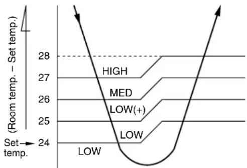
line
| Level | Temperature Range | |---|---| | HIGH | 27-28 | | MED | 26-27 | | LOW(+) | 25-26 | | LOW | 24-25 | | Low | 24-25 |Fig. 7-1-1 Auto setting of air volume
Table 7-1-1 Manual setting of FAN SPEED
| Indication of FAN SPEED | HIGH Air volume (m3/hr) |
| LOW | 430 (*430) |
| MED | 510 (*490) |
| HIGH | 650 (*550) |
* For model : RAS-07YKX, RAS-07YK-E, RAS-07YK-ES, RAS-07YKX-T
7-2. COOL Operation
(MODE of the remote control : COOL)
(1) Compressor, outdoor fan and operation display are controlled as shown in Fig. 7-2-1.
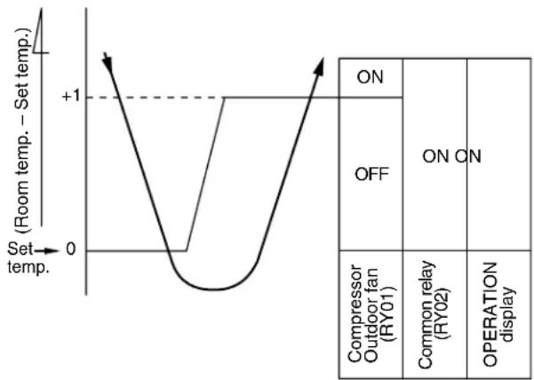
line
| Set temp. | Room temp. - Set temp. | | --------- | --------------------- | | 0 | +1 | | 1 | 0 |Fig. 7-2-1
(2) Relays RY01 and RY02 are turned on to energize the outdoor unit, and a cool operation is carried out.
1) When the FAN is set to AUTO, the indoor fan motor operates as shown in Fig 7-2-2.
2) When the FAN is set to LOW, MED, or HIGH, the indoor fan motor operates with a constant in volume as listed in Table 7-1-1.
line
| Set temp. | Room temp. - Set temp. | | --------- | --------------------- | | 0 | +4 | | 1 | +3 | | 2 | +2 | | 3 | +1 | | 4 | 0 |Fig. 7-2-2
(3) Once the setting is made, the operation mode is memorized in the microcomputer so that the same operation can be effected thereafter simply by pushing the START/STOP button.
7-2-1. Louver Control
(1) Vertical air flow louvers
Positions of vertical air flow louvers are automatically controlled according to the operation status (COOL, AUTO, DRY, FAN ONLY). Besides, positions of vertical air flow louvers can be arbitrarily set by pushing the [SET] button. The louver position which has been set by the [SET] button is stored in microcomputer, and the louver is automatically set at the stored position in the next operation.
(2) Swing
If the [AUTO] button is pushed during running operation, vertical air flow louvers start swinging. When the [AUTO] button is pushed again, swinging stops.
7-3. DRY Operation
(MODE of the remote control : DRY)
(1) Compressor, outdoor fan and operation display are controlled as shown in Fig. 7-3-1.
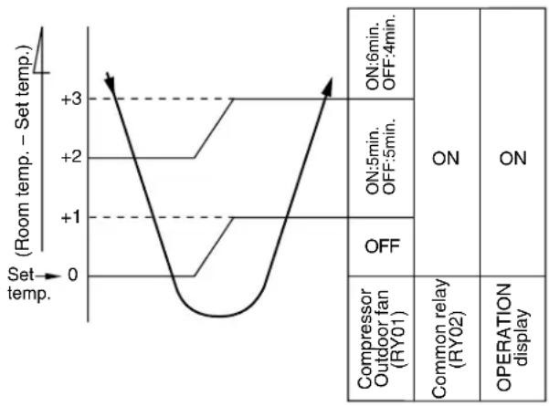
line
| Condition | Room temp. - Set temp. | |---|---| | ON:6min. OFF:4min. | +3 | | ON:5min. OFF:5min. | +2 | | OFF | +1 | | Compressor Outdoor fan (RY01) | 0 | | Common relay (RY02) | 3 | | OPERATION display | 0 |Fig. 7-3-1
- The microprocessor turns the compressor on and off at regular intervals (4 to 6 minutes on and/or off).
During the compressor off, the indoor fan will operate in the super low position. - The indoor fan will operate in the AUTO position.
(2) The pattern of operation depending on the relation between room temperature and set temperature is shown below:
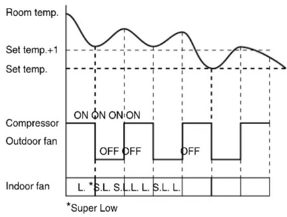
Fig. 7-3-2
7-4. AUTO Operation
(MODE of the remote control : AUTO)
(1) One of the 2 modes, Cooling or Dry is selected according to room temperature at which operation is to start, as shown in Fig. 7-4-1. The Fan mode will continue until room temperature reaches a level at which another mode is selected.
7-4-1. Temporary Auto
When the TEMPORARY button is pushed (1 sec), the set temperature is fixed at 24^ C and controlled in accordance with the chart shown in Fig. 7-4-1.
| (Room temp. - Set temp.) +4 +1 | Powerful Cooling mode | (The same cooling mode as the room temperature control is set at set temp. -1°C) The Louver moved downward. (DIRECT AUTO COOL) |
| Cooling mode | (The same cooling mode as the room temperature control is set at set temp. -1°C) | |
| Dry mode | (The same dry operation as the room temperature control is set at set temp. -1°C) |
Fig. 7-4-1
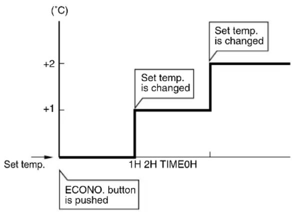
7-5. ECONO. Mode
When the ECONO. button is pushed, during COOL and AUTO operation, the OPERATION display is turned off and the ECONO. display is lit and the indoor unit operates quietly and mildly with controlling airflow.
7-5-1. Cooling
(1) In the ECONO. mode, the set temp. by the remote control is changed automatically as shown in Fig. 7-5-1.
(2) Fan speed → LOW
line
| Time | Set temp. (°C) | | :--- | :--- | | 1H 2H TIME0H | +1 | | End | +2 |Fig. 7-5-1
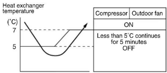
7-6. Low-Temperature Limit Control (Cooling Operation)
The microprocessor detects the indoor heat exchanger temperature so as to prevent freezing up the indoor heat exchanger.
Control is performed as shown in Fig. 7-6-1.
line
| Temperature (°C) | Value | | ---------------- | ----- | | 7 | | | 5 | |Fig. 7-6-1
7-7. Auto Restart Function
This unit is equipped with an Automatic restarting function which allows the unit to restart and resume the set operating conditions in the event of a supply power shutdown without the use of the hand control. The operation will resume without warning three minutes after the power is restored.
INFORMATION
The AUTO RESTART FUNCTION is set not to work on shipment from the factory, and so it is necessary to set it to function as required.
7-7-1. How to Set the Auto Restart
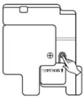
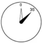
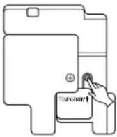
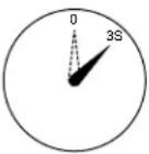
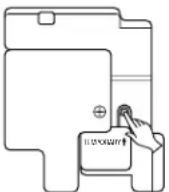
To set the Auto Restart function, proceed as follows: Access the TEMPORARY button located in the lower right hand corner beneath the hinged front panel of the indoor unit (please refer to section on PARTS NAME). The power supply to the unit must be on - the function will not be set if the power is off.
To enable the Auto Restart function, push the TEMPORARY button continuously for three seconds.
The unit will acknowledge the setting and beep three times. The system will now restart automatically.
The above Auto Restart settings can be carried out:
- When the system is stand-by (not running)
| OPERATION | MOTION | |
| Push the TEMPORARY button continuously more than three seconds. | Stand-by↓The system starts to operate. The green light will be lit.↓about three seconds afterThe unit beeps three times. The orange light will be lit.↓The system is operating. The orange light is lighting.If the system is not required to run at this time, push the TEMPORARY button once more or use the remote control and the unit will stop. | |
 |  | |
- When the system is operating
| OPERATION | MOTION | |
| Push the TEMPORARY button continuously more than three seconds. | Operating The green light is lit.↓The system stops to operate. The green light is turned off.↓about three seconds afterThe unit beeps three times.↓The system stops.If the system is not required to stop at this time, use the remote control and to restart. | |
 |  | |
During subsequent operation, the orange light goes on.
- The Auto Restart function will not accept an instruction if timer operation with the remote control is selected.
- During louver swing (AUTO) operation, after restarting by the Auto Restart function, the louver swing stops.
7-7-2. How to Cancel the Auto Restart
To cancel the Auto Restart function, proceed as follows:
Repeat the setting procedure: the unit will acknowledge the instruction and beep three times.
The system will now be required to manually restart with the remote control after the main supply is turned off.
Cancellation is carried out:
- When the system is stand-by (not running)
| OPERATION | MOTION |
Push the TEMPORARY button continuously more than three seconds.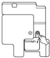  | Stand-by↓The system starts to operate. The orange light will be lit.↓about three seconds afterThe unit beeps three times. The green light will be lit.↓The system is operating.If the system is not required to run at this time, push the TEMPORARY button once more or use the remote control and Stop the unit. |
- When the system is operating
| OPERATION | MOTION | |
| Push the TEMPORARY button continuously more than three seconds. | Operating The orange light is lit.↓The system stops to operate. The orange light is turned off.↓about three seconds afterThe unit beeps three times.↓The system stops.If the system is not required to stop at this time, use the remote control and to restart. | |
 |  | |
During subsequent operation, the green light goes on.
7-7-3. In Case of Power Failure during the Timer Operation
(1) If ON-TIMER operation is reserved with setting of Auto Restart operation, it is cancelled with power failure. (The OPERATION lamp on the main unit goes on and off to inform of power failure.) In that case, try to reserve ON-TIMER operation once again.
(2) If OFF-TIMER operation is reserved without setting of Auto Restart operation, the reservation is cancelled with power failure. (The OPERATION lamp on the main unit goes on and off to inform of power failure.) In that case, try to reserve OFF-TIMER operation. When Auto Restart operation is set, OFF-TIMER reservation is also cancelled with power failure.
8. INSTALLATION PROCEDURE
8-1. Safety Cautions
For general public use
Power supply cord of parts of appliance for Outdoor use shall be more than polychloroprene sheathed flexible cord (design H05 RN-F), or cord designation 245 IEC 57.
CAUTION
TO DISCONNECT THE APPLIANCE FROM THE MAINS SUPPLY.
This appliance must be connected to the mains by means of a circuit breaker or a switch with a contact separation of at least 3 mm.
If this is not possible, a power supply plug with earth must be used. This plug must be easily accessible after installation. The plug must be disconnected from the power supply socket in order to disconnect the appliance completely from the mains.
DANGER
ENGAGE DEALER OR SPECIALIST FOR INSTALLATION.
FOR ELECTRICAL WORKS THE WIRING AND CABLES MUST BE PERFORMED IN COMPLIANCE WITH NATIONAL WIRING STANDARD OR REGULATION. IF INCORRECT AND INCOMPLETE WIRING IS CARRIED OUT, IT WILL CAUSE AN ELECTRICAL FIRE OR ELECTRICAL SHOCK.
USE THE SPECIFIED CABLE (1,5 to 2,0mm ^2 ) AND CONNECT TIGHTLY FOR INDOOR/OUTDOOR CONNECTION. CONNECT TIGHTLY AND CLAMP THE CABLE SO THAT EXTERNAL FORCE WILL BE ACTED ON THE TERMINAL.
` WIRE ROUTING MUST BE PROPERLY ARRANGED SO THAT CONTROL BOARD COVER IS FIXED PROPERLY.
` DO NOT DAMAGE OR SCRATCH THE CONDUCTIVE CORE AND INNER INSULATOR OF THE CABLES.
DO NOT DEFORM OR SMASH ON THE SURFACE OF THE CABLES. DO NOT PRESS OR FIX THE CORD AND CABLES FIRMLY WITH STAPLES, etc.
DO NOT USE THE EXTENSION CABLE FOR POWER SUPPLY CORD OR INTER-CONNECTING CABLE. NEVER EXECUTE THE CONNECTION OF WIRING WITH OTHER METHOD THAN THE APPROVED ONE. OTHERWISE, OVERHEAT, SMOKE OR FIRE MAY BE GENERATED BY CONTACT ERROR.
TURN OFF MAIN POWER SUPPLY AND BREAKER BEFORE ATTEMPTING ANY ELECTRICAL WORK. MAKE SURE ALL POWER SWITCHES AND BREAKER TURN OFF. FAILURE TO DO SO MAY CAUSE ELECTRIC SHOCK.
CONNECT THE CONNECTING CABLE CORRECTLY. IF THE CONNECTING CABLE IS CONNECTED BY WRONG WAY, ELECTRIC PARTS MAY BE DAMAGED.
` GROUNDING WIRE WORKS MUST BE CONSTRUCTED IN COMPLIANCE WITH INSTALLATION MANUAL.
DO NOT INSTALL NEAR CONCENTRATIONS OF COMBUSTIBLE GAS VAPORS. FAILURE TO FOLLOW THIS INSTRUCTION CAN RESULT IN FIRE OR EXPLOSION.
TO PREVENT OVERHEATING THE INDOOR UNIT AND CAUSING A FIRE HAZARD. PLACE THE UNIT WELL AWAY (MORE THAN 2M.) FROM HEAT SOURCE SUCH AS RADIATORS, HEAT REGISTORS. FURNACE, STOVES, etc.
IF A REFRIGERATION GAS LEAKS DURING INSTALLATION, BE SURE TO PERFORM VENTLATION. IF THE REFRIGERANT GAS COMES INTO CONTACT WITH FIRE, A POISONOUS GAS MAY OCCUR. WHEN INSTALLING AN AIR CONDITIONER, DO NOT ALLOW AIR OR MOISTURE TO REMAIN IN THE REFRIGERATION CYCLE. OTHERWISE, PRESSURE IN THE REFRIGERATION CYCLE MAY BECOME ABNORMALLY HIGH SO THAT A RUPTURE OR PERSONAL INJURY MAY BE CAUSED.
BE SURE TO USE THE CORD-CLAMPS AND THE ELECTRIC PARTS COVER TO THE SPECIFIED POSITION WITH ATTACHED TO THE PRODUCT. MOUNT THE ELECTRIC PARTS COVER FOR CABLES OF CONNECTING SECTION FIRMLY WITH THE SCREWS.
WARNING
- Never modify this unit by removing any of the safety guards or by-passing any of the safety interlock switches.
- Do not install in a place which cannot bear the weight of the unit. Personal injury and property damage can result if the unit falls.
- Before doing the electrical work, attach an approved plug to the power supply cord. And make sure the equipment to be earthed.
- Appliance shall be installed in accordance with national wiring regulations. If you detect any damage, do not install the unit. Contact your Toshiba dealer immediately.
CAUTION
- Exposure of unit to water or other moisture before installation will result in an electrical short. Do not store in a wet basement or expose to rain or water.
• After unpacking the unit, examine it carefully for possible damage. - Do not install in a place that can increase the vibration of the unit. Do not install in a place that can amplify the noise level of the unit or where noise and discharged air might disturb user's neighbors.
- To avoid personal injury, be careful when handling parts with sharp edges.
- Please read the installation manual carefully before installing the unit. It contains further important instructions for proper installation.
UK Plugs and Sockets etc (Safety) Regulations 1994 SI Number 1768
With regard to Schedule 3, Item 7 of the above UK Regulations, this appliance must be permanently connected to the fixed wiring of the main electrical supply by means other than the use of an approved 13 Amp. plug-top as outlined in the Regulations.
Electrical work must be carried by suitably qualified persons and in accordance with all relevant safety standards and codes of practice.
We recommend that the power supply for this appliance is derived from a suitably protected dedicated circuit.
(for U.K. only)
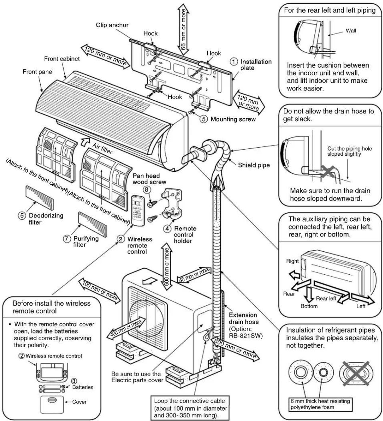
8-2. Installation Diagram of Indoor and Outdoor Units
For installation of the indoor unit, use the paper pattern on the back.
8-3. Installation
8-3-1. Optional Parts
| Part code | Parts name | Q'ty |
| A | Refrigerant pipingLiquid side : ø6,35 mmGas side : ø9,52 mm | Each one |
| B | Pipe insulating material(polyethylene foam, 6 mm thickness) | 1 |
| C | Putty, PVC tapes | Each one |
Fig 8-3-1 Air outlet
- Secure the outdoor unit with the anchor bolts if the unit is likely to be exposed to a strong wind.
- Use 8 or 10 anchor bolts.
| Part No. | Name of parts Q'ty | Part No. | Name of parts Q'ty |
| 1 | 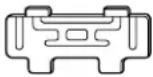 Installation plate x 1 Installation plate x 1 | 5 |  Mounting screw ø4 x 25 l x 6 Mounting screw ø4 x 25 l x 6 |
| 2 |  Wireless remote control x 1 Wireless remote control x 1 | 6 |  Deodorizing filter x 1 Deodorizing filter x 1 |
| 3 |  Batteries x 2 Batteries x 2 | 7 |  Purifying filter x 1 Purifying filter x 1 |
| 4 |  Remote control holder x 1 Remote control holder x 1 | 8 |  Pan head wood screwø3,1 x 16 l x 2 Pan head wood screwø3,1 x 16 l x 2 |
Others
| Name |
| Installation manual |
| Owner's manual |
This model is not equipped with an extension drain hose.
Option : For the extension drain hose, use an optionally available RB-821SW or commercially available one.
8-4. Indoor Unit
◆ Installation place
- A place which provides the spaces around the indoor unit as shown in the diagram in section 8-2.
- A place where there is no obstacle near the air inlet and outlet.
- A place which allows an easy installation of the piping to the outdoor unit.
- A place which allows the front panel to be opened.
CAUTION
- Direct sunlight to the indoor unit wireless receiver should be avoided.
- The microprocessor in the indoor unit should not be too close to r-f noise sources. (For details, see the owner's manual.)
- A place where there are no obstacles such as a curtain that may block the signal from the remote control.
- Do not install the remote control in a place exposed to direct sunlight or close to a heating source, such as a stove.
- Keep the remote control at least 1 m apart from the nearest TV set or stereo equipment. (This is necessary to prevent image disturbances or noise interference.)
- The location of the remote control should be determined as shown below.
8-4-1. Cutting a Hole and Mounting Installation Plate
When installing the refrigerant pipes from the rear.
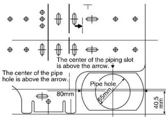
Fig. 8-4-2
(1) After determining the pipe hole position with the mounting plate (80 mm →), drill the pipe hole (ø65 mm) at a slight downward slant to the outdoor side.
NOTE :
- When drilling the wall that contains a metal lath, wire lath or metal plate, be sure to use a pipe hole brim ring sold separately.
For installation of the indoor unit, use the paper pattern on the back.
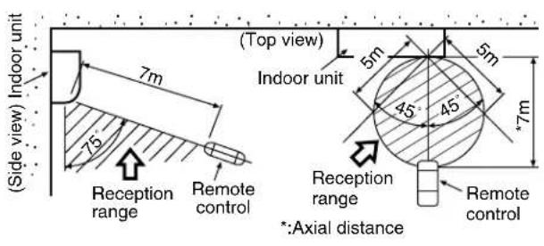
Fig. 8-4-1
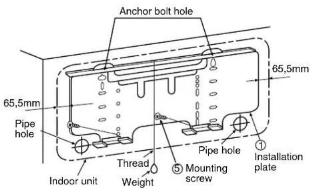
Fig. 8-4-3
(1) Securely fit the installation plate onto the wall by screwing it in the upper and lower parts to hook up the indoor unit.
(2) Install the installation plate horizontally in the wall.
(3) To mount the installation plate on a concrete wall with anchor bolts, utilize the anchor bolt holes as shown in the above figure.
CAUTION
When installing the installation plate with mounting screw, do not use the anchor bolt hole. Otherwise the unit may fall down and result in personal injury and property damage.
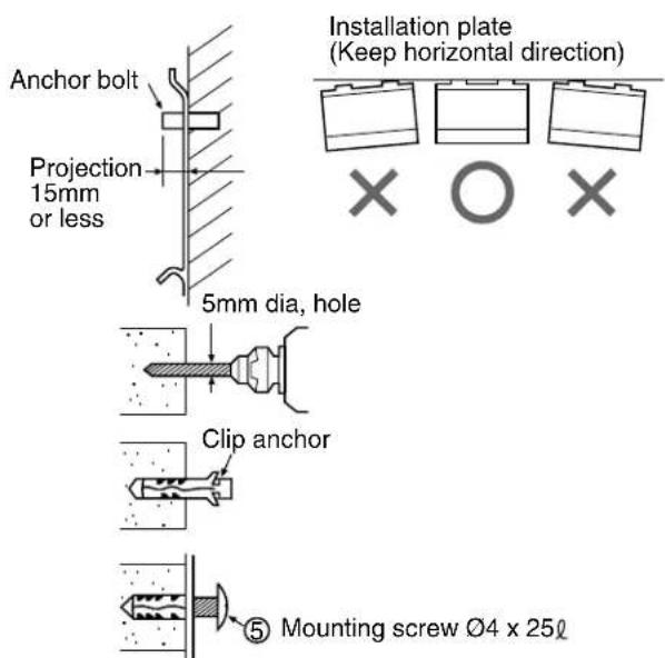
Fig. 8-4-4
CAUTION
Failure to firmly install the unit may result in personal injury and property damage if the unit falls.
- In case of block, brick, concrete or similar type walls, make holes in the wall.
- Insert clip anchors for appropriate ⑤ mounting screws.
NOTE :
• Install the installation plate using 4 to 6 pieces of mounting screw securing four corners with screws.
8-4-2. Electrical Work
(1) The supply voltage must be the same as the rated voltage of the air conditioner.
(2) Prepare the power source for exclusive use with the air conditioner.
CAUTION
- Use power specified above table.
- This appliance can be connected to the mains in either of the following two ways.
(1) Connection to fixed wiring: A switch or circuit breaker which disconnects all poles and has a contact separation of at least 3 mm must be incorporate in the fixed wiring. An approved circuit breaker or switches must be used.
(2) Connection with power supply plug: Attach power supply plug with power cord and plug it into wall outlet. An approved power supply cord and plug must be used.
NOTE :
- Perform wiring works so as to allow a generous wiring capacity.
| MODEL | RAS-07YKXRAS-07YK-ERAS-07YK-ES | RAS-10YKXRAS-11YKXRAS-10YK-ERAS-10YK-ESRAS-10YK-HX | RAS-07YKX-T RAS-10YKX-T |
| Power source 50Hz | *220–240V ~ Single-phase 50Hz | *220V ~ Single-phase | |
| Maximum running current | 5A 7,5A 5A 7,5A | ||
| Plug socket & fuse rating 16A | |||
| Wiring 1mm | ^2 or more | ||
* No adjustment is necessary.
8-4-3. Wiring Connection
WARNING
To plug the cable in the plug receptacle, take the following precaution.
THIS APPLIANCE MUST BE EARTHED.
IMPORTANT
THE WIRES IN THIS MAINS LEAD ARE COLORED IN ACCORDANCE WITH THE FOLLOWING CODE:
L : Brown
N : Blue
+ : Green and Yow
-LIVE
-NEUTRAL
-EARTH
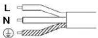
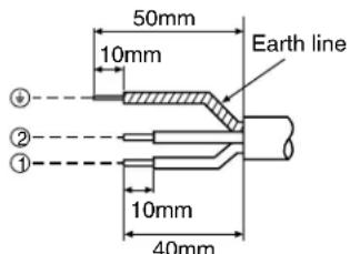
Fig. 8-4-5
As the colors of the flexible cord of this appliance may not correspond with the colored markings, to identify terminals in your plug, as follows:
Connect BROWN colored core to plug terminal marked letter "L".
Connect BLUE colored core to plug terminal marked letter "N".
Connect GREEN AND YELLOW colored core to plug terminal marked Earth Symbol “ ⏻ ”.
The installation of the cables has to be done in such a way that the basic insulated wires for the infrared sensor can not be touched.
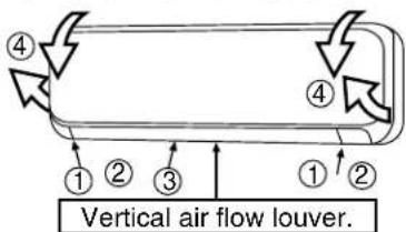
Fig. 8-4-6
How to open the screw cap
- Place your finger on the lower part and push up to open the screw cap.
(1) Open the screw caps and remove the two screws securing the front cabinet.
(2) Close the screw caps as behind.
(3) Open the vertical airflow louver horizontally by hand.
(4) Slightly open the lower part of the front cabinet then pull the upper part of the front cabinet toward you to remove it from the rear plate.
Taking out the power cord
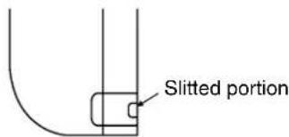
- Cut off the slitted portion in the side face of the rear panel to take out the power cord. After this, remove burrs, sharp edges, etc., to smooth the cut face..
(For RAS-07YK-E, RAS-07YK-ES, RAS-10YK-E, RAS-10YK-ES only)
For the air conditioner that has no power cord, connect a power cord to it as mentioned below.
• After removing the front cabinet, remove the terminal cover and the cord clamp.
- Connect and secure the power supply cord and secure the cord clamp and the terminal cover.
- Cut the rear panel following the cutting mark and put the power supply cord through the notch.
- Be sure to smooth out the notch with a file, etc.
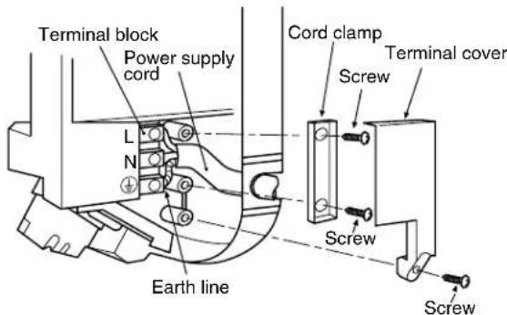
Fig. 8-4-7
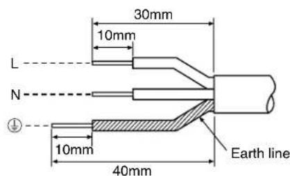
NOTE :
- Use standard wire only.
- Wire type: More than H05-RN-F
Fig. 8-4-8
Wiring of the connecting cable can be carried out without removing of the front panel.
(1) Remove the front panel.
Fully open the front panel. Disengage the support arm located in the upper center while pushing its handle leftwards, and then remove the front panel toward you.
(2) Remove the terminal cover and cord clamp.
(3) Insert the connecting cable (according to local codes) into pipe hole on the wall.
(4) Take out the connecting cable through the cable slot on the rear panel so that it is exploded by about 15 cm long in the front side.
(5) Insert the connecting cable fully into the terminal block and secure it by screw tightly.
(6) Tightening torque:1,2 N•m (0,12 kgf•m)
(7) Secure the connecting cable with the cord clamp.
(8) Fix the terminal cover and front panel on the indoor unit.
CAUTION
- Be sure to refer the wiring system diagram labeled inside the front panel.
- Check local electrical codes and also any specific wiring instructions or limitation.
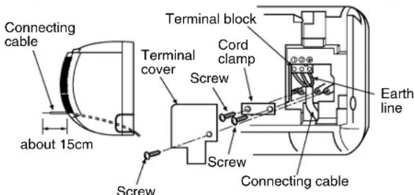
Fig. 8-4-9
For a three conductor cable
NOTE :
- Use stranded wire only.
- Wire type: More than H05 RN-F
Fig. 8-4-10
Install the front cabinet through the opposite order of "How to remove the front cabinet".
When the panel is removed and mounted again, take the following actions:
After fastening the two screws, one each at the left and right of the air outlet, be sure to push the upper center ① right end ② , left end ③ and the lower center ④ of the air outlet, and confirm that no gap is left between the front cabinet and the rear plate.
- If cooling (dry) operation is made without pushing the air outlet, dew can be deposited on the front cabinet surface. In addition a gap between the front cabinet and the rear plate will become wider, spoiling the appearance.
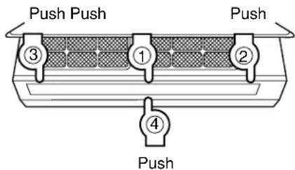
Fig. 8-4-11
8-4-4. Piping and Drain Hose Installation
- After scribing slits of the front panel and the rear panel by a knife or a marking-off pin, cut them by a pair of nippers or the like.
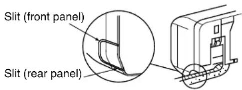
Fig. 8-4-12
- After scribing the slit of the front panel and slit in the lower part of the rear panel by a knife or a marking-off pin, cut them by a pair of nippers or the like.

Fig. 8-4-13
Bend the connecting pipe so that it is laid within 43 mm above the wall surface. If the connecting pipe is laid exceeding 43 mm above the wall surface, the indoor unit may unstably be set on the wall. When bending the connecting pipe, make sure to use spring bender so as not to crush the pipe.
Bend the connection pipe within a radius of 30 mm.
To connect pipe after installation of unit (figure)
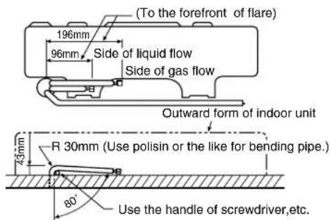
Fig. 8-4-14
NOTE :
If the pipe is bent incorrectly, the indoor unit may unstably be set on the wall.
After passing the connecting pipe through the pipe hole, connect the connecting pipe to auxiliary pipes and wrap the facing tape around them.
CAUTION
- Bind the auxiliary pipes (two) and connecting cable with facing tape tightly. In case of leftward piping and rear-leftward piping, bind the auxiliary pipes (two) only with facing tape.
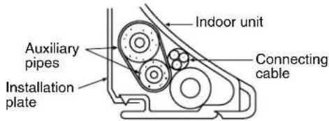
- Carefully arrange pipes so that any pipe does not stick out of the rear plate of the indoor unit.
- Carefully connect the auxiliary pipes and connecting pipes to each other and cut off the insulating tape wound on the connecting pipe to avoid double-taping at the joint, moreover, seal the joint with the vinyl tape, etc.
- Since dewing results in a machine trouble, make sure to insulate both the connecting pipes. (Use polyethylene foam as insulating material.)
- When bending a pipe, carefully do it not to crush it.
8-4-5. Indoor Unit Installation
(1) Pass the pipe through the hole in the wall, and hook the indoor unit on the installation plate at the upper hooks.
(2) Swing the indoor unit to right and left to confirm that it is firmly hooked up on the installation plate.
(3) While pushing the indoor unit onto the wall by the lower part, hook it up on the installation plate by the lower part. Pull the indoor unit toward you by the lower part to confirm that it is firmly hooked up on the installation plate.
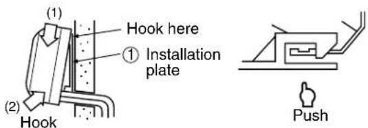
Fig. 8-4-15
- For detaching the indoor unit from the installation plate pull the indoor unit toward you while pushing its bottom up by the specified parts.
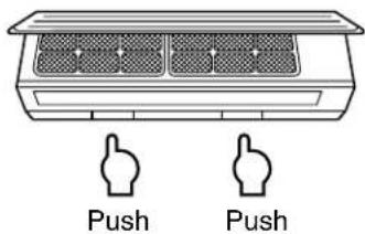
Fig. 8-4-16
8-4-6. Drainage
(1) Run the drain hose sloping downwards.
NOTE :
- Hole should be made at a slight downward slant to the outdoor side.
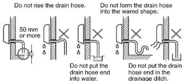
Fig. 8-4-17
(2) Put water in the drain pan and make sure that the water is drained outdoors.
(3) When connecting extension drain hose, insulate the connecting part of extension drain hose with shield pipe.
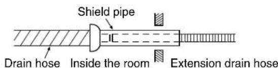
Fig. 8-4-18
CAUTION
Arrange the drain pipe for proper drainage from the unit.
Improper drainage can result in damage to property.
This air conditioner has the structure designed to drain water collected from dew, which forms on the back of the indoor unit, to the drain pan.
Therefore, do not store the power cord and other parts at a height above the drain guide.
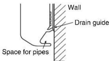
Fig. 8-4-19
8-5. Outdoor Unit
Installation place
- A place which provides the spaces around the outdoor unit as shown in the diagram in page 19.
- A place which can bear the weight of the outdoor unit and does not allow an increase in noise level and vibration.
- A place where the operation noise and discharged air do not disturb your neighbors.
- A place which is not exposed to a strong wind.
- A place free of a leakage of combustible gases.
- A place which does not block a passage.
- When the outdoor unit is to be installed in an elevated position, be sure to secure its feet.
- An allowable length of the connecting pipe is up to 10 m.
- An allowable head level is up to 5 m.
- A place where the drain water does not raise any problem.
CAUTION
(1) Install the outdoor unit without anything blocking the air discharging.
(2) When the outdoor unit is installed in a place exposed always to a strong wind like a coast or on a high story of a building, secure the normal fan operation using a duct or a wind shield.
(3) Specially in windy area, install the unit to prevent the admission of wind.

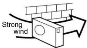

Fig. 8-5-1
CAUTION
Installation in the following places may result in trouble. Do not install the unit in such places.
• A place full of machine oil.
• A saline place such as coast.
• A place full of sulfide gas.
- A place where high-frequency waves are likely to be generated as from radio equipment, welders, and medical equipment.
8-5-1. Refrigerant Piping Connection
(1) Cut the pipe with a pipe cutter.
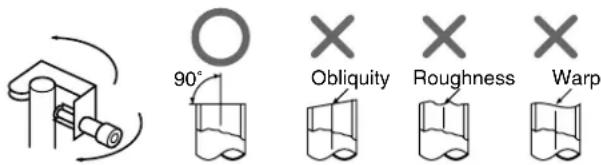
Fig. 8-5-2
(2) Insert a flare nut into the pipe, and flare the pipe.
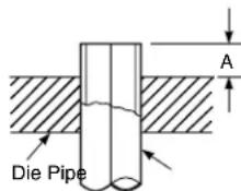
Fig. 8-5-3
| Outer dia. | A (mm) R22/R410A | |
| Imperial | Rigid | |
| 6,35mm | 1,0 ~ 1,5/1,5 ~ 2,0 | 0,5 ~ 1,0/1,0 ~ 1,5 |
| 9,52mm | 1,0 ~ 1,5/1,5 ~ 2,0 | 0,5 ~ 1,0/1,0 ~ 1,5 |
Align the centers of the connecting pipes and tighten the flare nut as far as possible with your fingers.
Then tighten the nut with a spanner and torque wrench as shown in the figure.
CAUTION
- Do not apply excess torque. Otherwise, the nut may crack depending on the installation conditions.
| Outer dia. | Tightening touque N•m (kgf•m) |
| 6,35mm | 16 ~ 18 (1,6 ~ 1,8) |
| 9,52mm | 30 ~ 42 (3,0 ~ 4,2) |
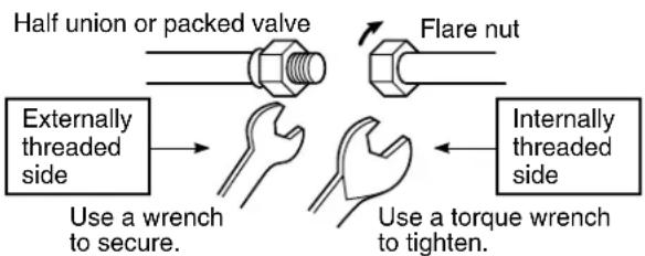
flowchart
graph TD
    A["Half union or packed valve"] --> B["Flare nut"]
    C["Externally threaded side"] --> D["Use a wrench to secure."]
    E["Internally threaded side"] --> F["Use a torque wrench to tighten."]
Fig. 8-5-4
8-5-2. Vacuum Pumping
INFORMATION
In order to prevent any other refrigerant from being charged accidentally, each port of the manifold has been changed in shape.
Differences in Port Size between Conventional R22 and R410A
| Manifold for R22 Manifold for R410A | |
| Port size | 7/16 UNF 1/2 UNF20 threads per inch 20 threads per inch |
AIR PURGE
Evacuate the air in the connecting pipes and in the indoor unit using vacuum pump.
Do not use the refrigerant in the outdoor unit.
For details, see the manual of vacuum pump.
(1) Connect the charge hose (A) from the manifold valve to the charge inlet of the gas side packed valve.
(2) Connect the charge hose (B) to the port of vacuum pump.
(3) Open fully the low pressure side handle of the manifold valve.
(4) Operate the vacuum pump.
(5) Close the low pressure side handle of manifold valve after vacuumizing and stop the vacuum pump.
Continue vacuumizing more than 15 minutes and check the pressure gage indicates -0,1MPa (-76 cmHg).
(6) Open the stems of packed valves A and B all the way.
(7) Securely tighten the stem cap to each of the packed valve stems.
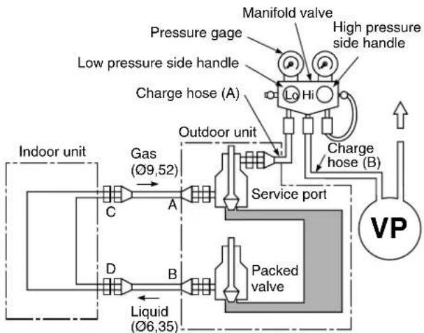
flowchart
graph TD
    A["Indoor unit"] --> B["Gas (Ø9,52)"]
    B --> C["A"]
    C --> D["Service port"]
    D --> E["Packed valve"]
    E --> F["Charge hose (B)"]
    F --> G["High pressure side handle"]
    G --> H["Pressure gage"]
    H --> I["Charge hose (A)"]
    I --> J["Lo Hi"]
    J --> K["Outdoor unit"]
    K --> L["Liquid (Ø6,35)"]
    L --> M["D"]
    M --> N["B"]
    N --> O["C"]
    O --> P["Manifold valve"]
Fig. 8-5-5
CAUTION
- KEEP IMPORTANT 4 POINTS FOR INSTALLATION (PIPING WORK)
(1) Take away dust and moisture (Inside of the connecting pipes.)
(2) Tight connection (between pipes and unit)
(3) Evacuate the air in the connecting pipes using VACUUM PUMP.
(4) Check gas leak (connected points)
- Open the valve stem all the way out; so not try to open it beyond the stopper.
- Securely tighten the valve stem cap with the wrench or like.
- Valve stem cap tightening torque is as follows;
Gas pipes side (Ø9,52) : 30 \~ 42 N•m (3,0 \~ 4,2 kgf•m)
Liquid pipe side (∅6,35): 16 \~ 18 N•m (1,6 \~ 1,8 kgf•m)
Service port cap : 9 \~ 10 N•m (0,9 \~ 1,0 kgf•m)
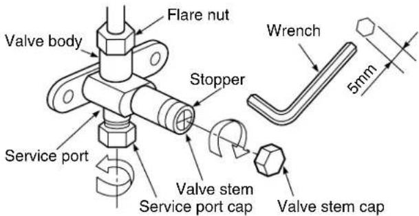
Note : Service port at Gas pipes valve only.
Fig. 8-5-6
8-5-3. Wiring Connection
(1) Remove the electric parts cover from the outdoor unit. (1 screw)
(2) Connect the connecting cable to the terminals as identified with their respective matched numbers on the terminal block of indoor and outdoor units. (Strip the sheath of connecting cable with following stripping length to and insert into the terminal block.)
(3) When connect the connecting cable to outdoor unit terminal, make a loop as shown in the installation diagram of indoor and outdoor unit, to prevent water coming in the outdoor unit.
(4) Insulate the unused cords (conductors) with water coming in the outdoor unit. Process them so that they do not touch any electrical or metal parts.
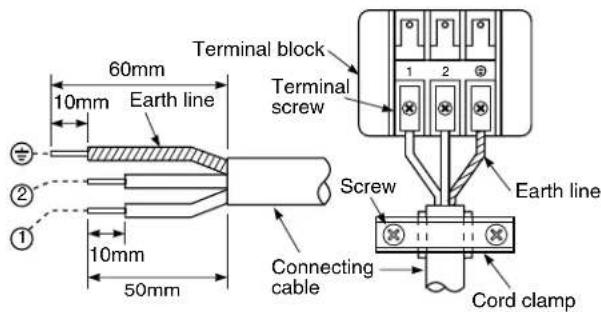
For a three conductor cable
Fig. 8-5-7
CAUTION
- Wrong wiring connections may cause some electrical parts to burn out.
- Be sure to comply with local code on running the wire from the indoor unit to outdoor unit. (size of wire and wiring method etc.)
- Every wire must be connected firmly.
NOTE :
• Wipe type : More than H05 RN-F
8-6. Others
8-6-1. Gas Leak Test
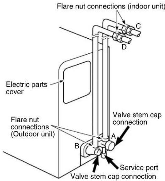
Fig. 8-6-1
- Check the flare nut connections, valve stem cap connections and service cap connections for gas leak with a leak detector or soap water.
8-6-2. Test Operation
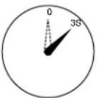
To switch the TEST RUN (COOL) mode, push TEMPORARY button for 10 sec. (The beeper will make a short beep.)
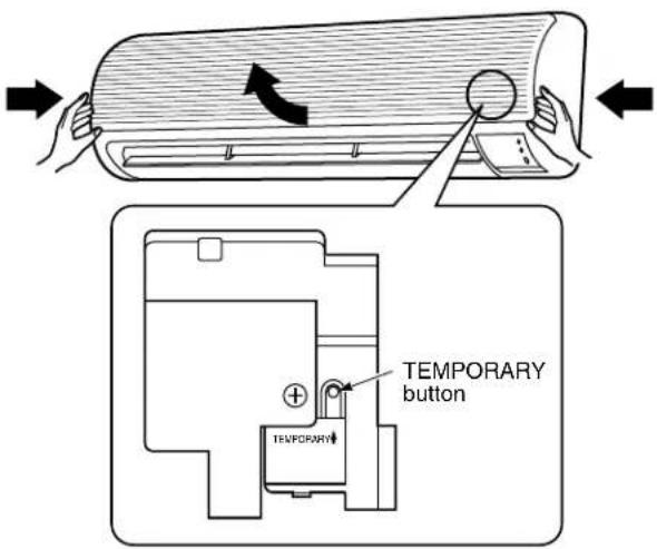
Fig. 8-6-2
8-6-3. Auto Restart Setting
This product is designed so that, after a power failure, it can restart automatically in the same operating mode as before the power failure.
INFORMATION
The product was shipped with Auto Restart function in the off position. Turn it on as required.
* See detail in section 7-7. Auto Restart Function
9. TROUBLESHOOTING CHART
TROUBLESHOOTING PROCEDURES :
- Following details of "What to be pre-checked first", make sure of the basic items.
- When there is no trouble corresponding to above, check in detail the faulty parts following “How to judge faulty parts by symptoms” later.
9-1. What to be Prechecked First
9-1-1. Power Supply Voltage
The line voltage must be AC 220–240V (220V for RAS-07YKX-T, RAS-10YKX-T).
If the line voltage is not within this range, this air conditioner may not work normally.
9-1-2. Incorrect Cable Connection between Indoor and Outdoor Units
The indoor unit is connected to the outdoor unit with 3 cables. Make certain that the indoor and outdoor units have been connected properly, with terminals assigned the same numbers wired to each other. If the connectors are not connected as specified, the outdoor unit will not operate normally.
9-1-3. Misleading but Good Operations (Program Controlled Operation)
The microcomputer performs the operations listed in Table 9-1-1 to control the air conditioner. If a claim is made on the operation, check whether it corresponds to the contents in the Table 9-1-1. If it does, it is an indispensable operation for the control and maintenance of the air conditioner: it is not a failure of the unit.
Table 9-1-1
| No. | Operation of air conditioner Description | |
| 1 | When the power plug or the power cord of the indoor unit is inserted, the OPERATION lamp on the setting indication part blinks. | The OPERATION lamp blinks, indicating that power is turned on.If this happens, push the START/STOP button once to cause the lamp to stop blinking. A power outage also causes the lamp to blink. |
| 2 | Fan speed remains unchanged in the dry mode. | Fan speed is automatically controlled in the dry mode. |
| 3 | The compressor will not switch on or off even when the thermo. control is operated in the dry operation. | In the dry mode, the compressor goes on and off at regular intervals, independent of the thermo. control. |
| 4 | Compressor does not work though room temperature is in the range of turning the compressor on. | Compressor does not work while the compressor restart delay (3-min.) timer is active. The same is true after power is turned on, as the time is still active. |
| 5 | During automatic operation, the operation mode changes. | After selection of the cooling and dry operation, the operation mode is selected again when the compressor off mode continues for 15 min. according to the room temperature. And after selection of the dry operation, the condition of the room temperature which is Room temp.≥Set temp.+1 and which is Room temp.<Set temp.-4 continues for 15 min., the operation mode is selected again. |
| 6 | When the power is turned on, the operation starts automatically. | When the auto restart controlling is selected, the operation is performed automatically in the previous operation mode after the power supply has been turned on. |
9-2. Primary Judgement of Trouble Sources
9-2-1. Role of Indoor Unit Controller
The indoor unit controller receives the operation commands from the remote control and assumes the following functions.
- Measurement of the draft air temperature of the indoor heat exchanger by using the thermo sensor (TA).
- Louver motor control
• Control of the indoor fan motor operation
• Control of the LED display - Control of the outdoor unit compressor and the outdoor fan motor.
9-2-2. Display of Abnormalities and Judgement of the Abnormal Spots
The indoor unit of this machine observes the operation condition of the air conditioner and displays the contents of the self-diagnosis as block displays on the display panel of the indoor unit.
Table 9-2-1
| Block display Description | ||
| A | OPERATION display blinking (1 Hz) Power failure (when power is ON) | |
| B | OPERATION display blinking (5 Hz) Thermo. sensor (TA) short/break | |
| C | OPERATION display blinking (5 Hz) | Heat exchanger sensor (TC) short/break |
| D | OPERATION display blinking (5 Hz) Indoor fan lock, abnormality of indoor fan | |
| E | OPERATION display blinking (5 Hz) Indoor P.C. board failure | |
| F | OPERATION, TIMER and FAN-ONLY display blinking (5 Hz) | Gas shortage, other refrigerant cycle troubleHeat exchanger sensor open/break/shortOverload relay trouble |
(1) Judgement from defective operation or abnormal operation
Table 9-2-2
| Symptom Check | Primary judgement | ||
| No reaction on remote control operation | Turn off the power once, turn it on again and try to operate the remote control again. | Remote control is not possible. | The indoor part (including the remote control) is defective. |
| Remote control is possible. OK. | |||
| The outdoor fan does not rotate | The compressor operates. | The outdoor part is defective. (outdoor fan motor) | |
| The compressor does not operate. The inside part is defective. | |||
(2) Self-diagnosis with remote control
With the indoor unit control, self-diagnosis of protective circuit action can be done by turning the remote control operation into service mode, operating the remote control, observing the remote control indicators and checking whether TIMER lamp blinks (5 Hz).
[ METHOD]
① Push the [CHK] button with a thin tip of pencil or others. The remote control display shows "00".
② Push “▲” key of TEMP. one by one.
The receiving beep “Pi!” is heard, and the timer lamp of the air conditioner blinks.
(5 times for 1 sec.)
③ Operating “▲” key, the 35 check codes from “00” to “22” are sent.
④ To reduce the check code number, push the “▼” key of TEMP.
⑤ If the check code agrees with the error code, the receiving beep continues ringing "Pi, Pi, Pi ..." (for approx.10 sec.), and all the LED of air conditioner blink. (5 times for 1 sec.)
[ To release the servicing check ]
⑥ Push the [START/STOP] button. Display screen returns to one before check. The servicing check operation can be also released by [ACL] button.
Table 9-2-3
| Block level Diagnosis function | Judgment and action | |||||
| Check code | Block | Check code | Symptom | Air Conditioner status | Condition | |
![TOSHIBA RAS-10YA-HX - [ To release the servicing check ] - 1](/content/2026/06/1186871/images/edbf5801228ad0f9ebabad046f90d0f1180d887c6290d243a97a9033017ca7e5.jpg) | Indoor P.C. board | ![TOSHIBA RAS-10YA-HX - [ To release the servicing check ] - 2](/content/2026/06/1186871/images/ca7c17e43f31e9628d7a765b55b073aca171f6e8c81cf940e46712e5e35a9466.jpg) | Thermo. sensor short/break. | Continued operation | Indicated when detected abnormal | 1.Check thermo. sensor.2.If it is OK, check P.C. board. |
![TOSHIBA RAS-10YA-HX - [ To release the servicing check ] - 3](/content/2026/06/1186871/images/97cd06ca53ae05272c1a565294440317ecedd42bb81e7355a8e694e0466e97bd.jpg) | Heat exchanger sensor short/break. | Continued operation | Indicated when detected abnormal | 1.Check heat exchanger sensor.2.If it is OK, check P.C. board. | ||
![TOSHIBA RAS-10YA-HX - [ To release the servicing check ] - 4](/content/2026/06/1186871/images/f4d398d4e532ab5e6144e1de3ac1dc926106c25b52abaec842a346511e1d10ca.jpg) | Indoor fan lock, abnormality of indoor fan or thermal fuse break. | All off | Indicated when detected abnormal | |||
![TOSHIBA RAS-10YA-HX - [ To release the servicing check ] - 5](/content/2026/06/1186871/images/a303d84e194e806ab710df1c87f7da2c4022562c71f7f652eb7cae21eaff5a64.jpg) | Abnormality of other indoor unit P.C. board. | All off Indicated when detected abnormal | Replace P.C. board. | |||
| Contents detected by the check codes “04” to “18” are stored in memory of the microcomputer even if the power supply is turned off. Therefore, contents of operations in the past are all displayed. | ||||||
9-3. Troubleshooting Flowcharts
9-3-1. Power can not be Turned on (No Operation at All)
(1) Is the supply voltage normal?
(2) Is the connection to the AC output OK.?
flowchart
graph TD
    A["Shut off the power supply from AC outlet once and turn it on after 5 seconds."] --> B["Does the OPERATION lamp blink?"]
    B -->|NO| C["Does the power turn on by pushing the [START/STOP"] button of the remote control?]
    B -->|YES| D["Does the power turn on by pushing the [START/STOP"] button of the remote control?]
    D -->|NO| E["Does the transmission indicator of remote control flash normally and transmit certainly?"]
    D -->|YES| F["(No problem)"]
    E -->|NO| G["Remote control is defective."]
    E -->|YES| H["Replace the remote control."]
    I["Is the secondary voltage of SW transformer (T01) measured DC12V, and DC7V?"] -->|NO| J["Is the indication voltage (DC12V or 5V) of main PC board correct?"]
    J -->|NO| K["Does the fuse (F01) blow?"]
    K -->|YES| L["Parts (R21, R22, SG01, C15, C01, DB01, C02, Q01, T01) are defective."]
    K -->|NO| M["Does the thermal fuse blow? (Under PF. Terminal)"]
    M -->|YES| N["Wrong wiring of AC cord or connecting cable is defective."]
    M -->|NO| O["Is the indication voltage (DC12V or 5V) of main PC board correct?"]
    O -->|YES| P["Does the CN13 connector the wrong connecting?"]
    P -->|NO| Q["P.C. board is defective."]
    P -->|YES| R["Is the secondary voltage of SW transformer measured DC12V, and DC7V?"]
    R -->|YES| S["Is the secondary voltage of SW transformer (T01) or Tr (Q01) for power supply is defective."]
    R -->|NO| T["Re-wiring the cable."]
    T --> Q
    Q --> U["Replace the main P.C. board."]
    S --> V["Motor is defective."]
    S --> W["Re-wiring the cable."]
    T --> X["Switch off the power supply once, and turn it on again after disconnecting the motor connector CN10*"]
    X --> Y["Is the secondary voltage of SW transformer (T01) or Tr (Q01) for power supply is defective."]
*Be sure to disconnect the motor connector CN10 after shut off the power supply, or it will be a cause of damage of the motor.
9-3-2. Power can not be Turned on after Replacing Indoor P.C. Board
flowchart
graph TD
    A["Connect the AC Power supply"] --> B{Does the OPERATION lamp blink?}
    B -->|NO| C{Is it wired as shown in Figure below?}
    C -->|NO| D["Return the wiring of the power relay is returned to the normal procedure."]
    C -->|YES| E["To the paragraph of "No Power turns on"."]
    B -->|YES| F["Black: Indoor terminal block 1 2 + White"]
    C -->|YES| G["Blue: Power terminal block + N L"]
    G --> H["Brown: PC board C02 3 RY01 4 3 RY02 T02"]
    H --> I["Output"]
9-3-3. Outdoor Unit does not Operate
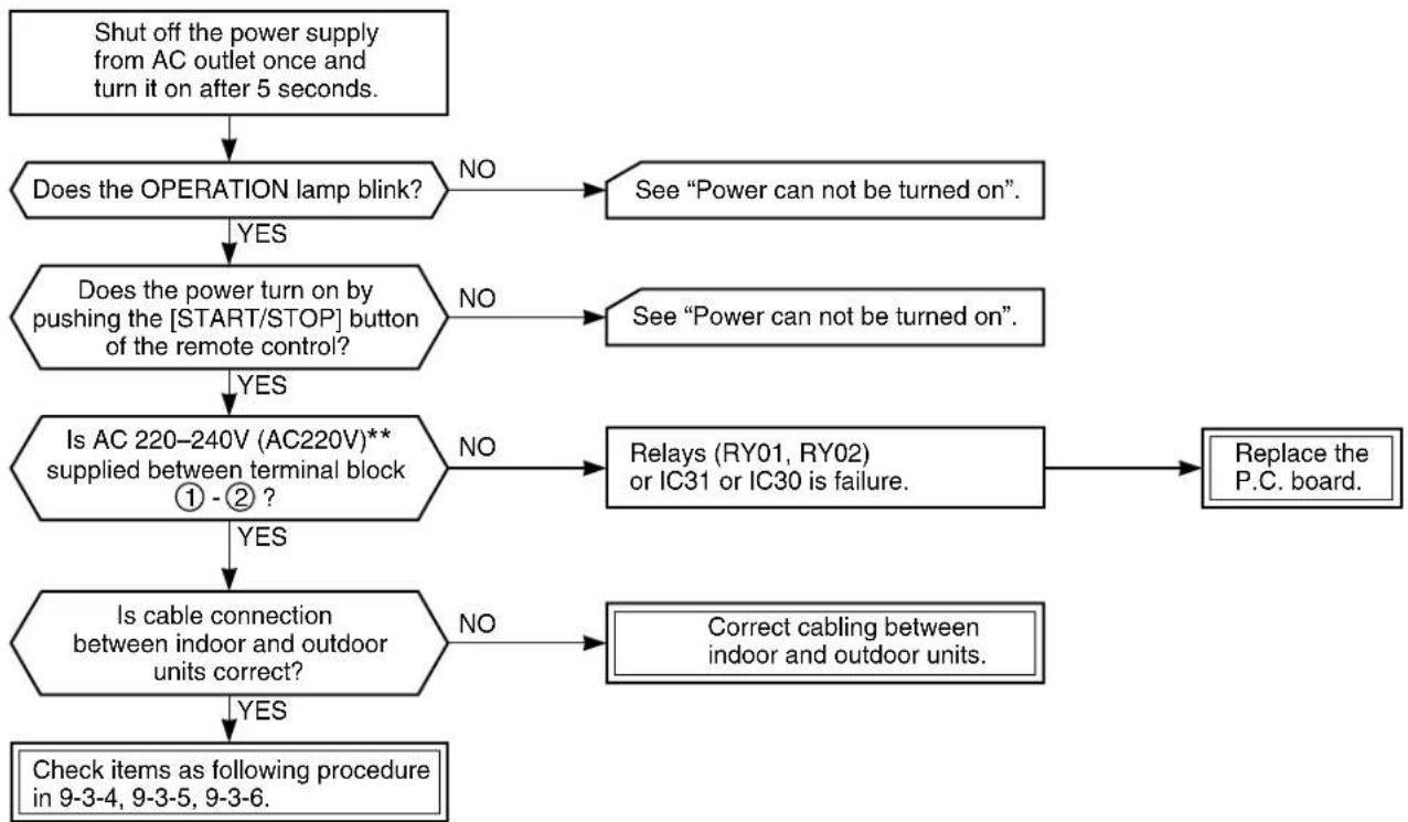
flowchart
graph TD
    A["Shut off the power supply from AC outlet once and turn it on after 5 seconds."] --> B{Does the OPERATION lamp blink?}
    B -->|NO| C["See "Power can not be turned on"."]
    B -->|YES| D{Does_the_power_turn_on_by_pushing_the["START/STOP"] button of the remote control?}
    D -->|NO| E["See "Power can not be turned on"."]
    D -->|YES| F{Is AC 220-240V (AC220V)** supplied between terminal block ① - ② ?}
    F -->|NO| G["Relays (RY01, RY02) or IC31 or IC30 is failure."]
    F -->|YES| H{Is cable connection between indoor and outdoor units correct?}
    H -->|NO| I["Correct cabling between indoor and outdoor units."]
    H -->|YES| J["Check items as following procedure in 9-3-4, 9-3-5, 9-3-6."]
    C --> K["Replace the P.C. board."]
    E --> K
    G --> K
    I --> K
** for model RAS-07YKX-T, RAS-10YKX-T
9-3-4. Only Compressor does not Operate
flowchart
graph TD
    A["Shut off the power supply from AC outlet once and turn it on after 5 seconds."] --> B["Does the OPERATION lamp blink?"]
    B -->|NO| C["See "Power can not be turned on"."]
    B -->|YES| D["Does the power turn on by pushing the [START/STOP"] button of the remote control?]
    D -->|NO| E["See "Power can not be turned on"."]
    D -->|YES| F["Is the voltage across the indoor terminal (① -②) AC 220-240V (AC 220V)**?"]
    F -->|NO| G["Relays (RY01, RY02) or IC31 or IC30 is failure."]
    G --> H["Replace the P.C. board."]
    F -->|YES| I["Is cable connection between indoor and outdoor units correct?"]
    I -->|NO| J["Correct cabling between indoor and outdoor units."]
    I -->|YES| K["Is the voltage across the outdoor terminal (① -②) AC 220-240V (AC 220V)**?"]
    K -->|NO| L["Cables between indoor and outdoor units are defective."]
    K -->|YES| M["Are all the cords for compressor normal?"]
    M -->|NO| N["Re-wire or replace the defective cords."]
    M -->|YES| O["Is the compressor motor winding normal? (Check the winding resistor.)"]
    O -->|NO| P["Compressor is defective."]
    O -->|YES| Q["Is the capacitor for compressor normal?"]
    Q -->|NO| R["Capacitor is defective."]
    Q -->|YES| S["Is the overload relay normal?"]
    S -->|NO| T["Overload relay is defective."]
    S -->|YES| U["Does the compressor start?"]
    U -->|NO| V["Compressor is defective."]
    U -->|YES| W["Compressor starts but it stops after a while?"]
    W -->|YES| X["Is the gas quantity normal? (Check the pressure)"]
    X -->|NO| Y["Gas shortage (Gas leakage)."]
    X -->|YES| Z["Compressor is defective"]
** for model RAS-07YKX-T, RAS-10YKX-T
9-3-5. Only Outdoor Fan does not Operate
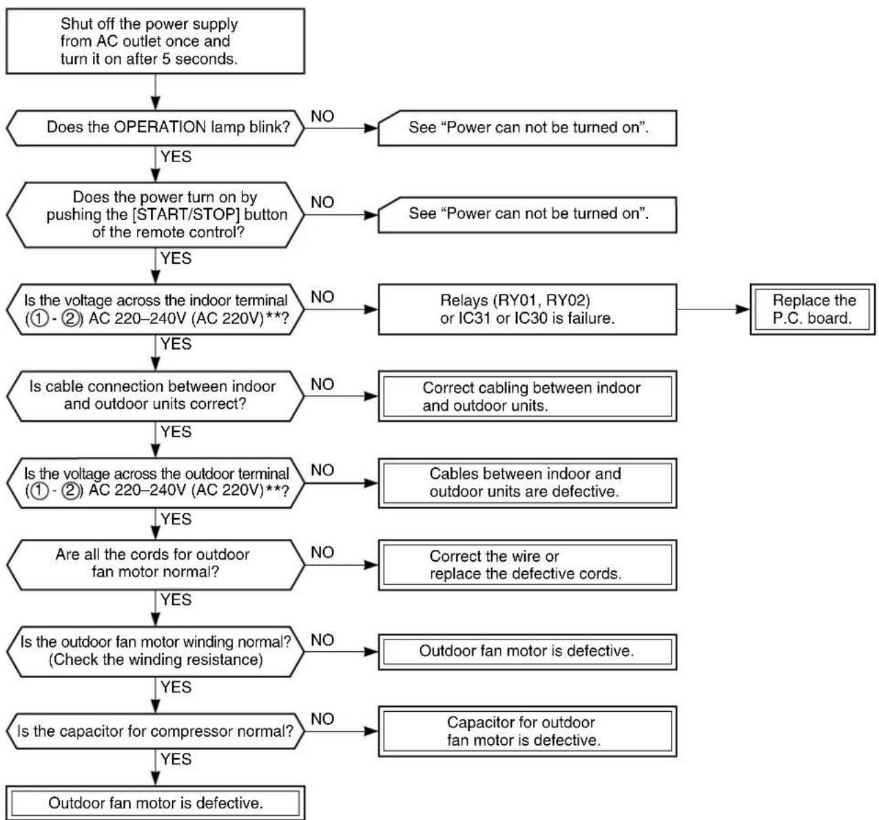
flowchart
graph TD
    A["Shut off the power supply from AC outlet once and turn it on after 5 seconds."] --> B{Does the OPERATION lamp blink?}
    B -->|NO| C["See "Power can not be turned on"."]
    B -->|YES| D{Does_the_power_turn_on_by_pushing_the["START/STOP"] button of the remote control?}
    D -->|NO| E["See "Power can not be turned on"."]
    D -->|YES| F{Is the voltage across the indoor terminal (① - ②) AC 220-240V (AC 220V)**?}
    F -->|NO| G["Relays (RY01, RY02) or IC31 or IC30 is failure."]
    F -->|YES| H{Is cable connection between indoor and outdoor units correct?}
    H -->|NO| I["Correct cabling between indoor and outdoor units."]
    H -->|YES| J{Is the voltage across the outdoor terminal (① - ②) AC 220-240V (AC 220V)**?}
    J -->|NO| K["Cables between indoor and outdoor units are defective."]
    J -->|YES| L{Are all the cords for outdoor fan motor normal?}
    L -->|NO| M["Correct the wire or replace the defective cords."]
    L -->|YES| N{Is the outdoor fan motor winding normal? (Check the winding resistance)}
    N -->|NO| O["Outdoor fan motor is defective."]
    N -->|YES| P{Is the capacitor for compressor normal?}
    P -->|NO| Q["Capacitor for outdoor fan motor is defective."]
    P -->|YES| R["Outdoor fan motor is defective."]
    R --> S["End"]
** for model RAS-07YKX-T, RAS-10YKX-T
9-3-6. Only the Indoor Fan does not Operate
< Check procedure >
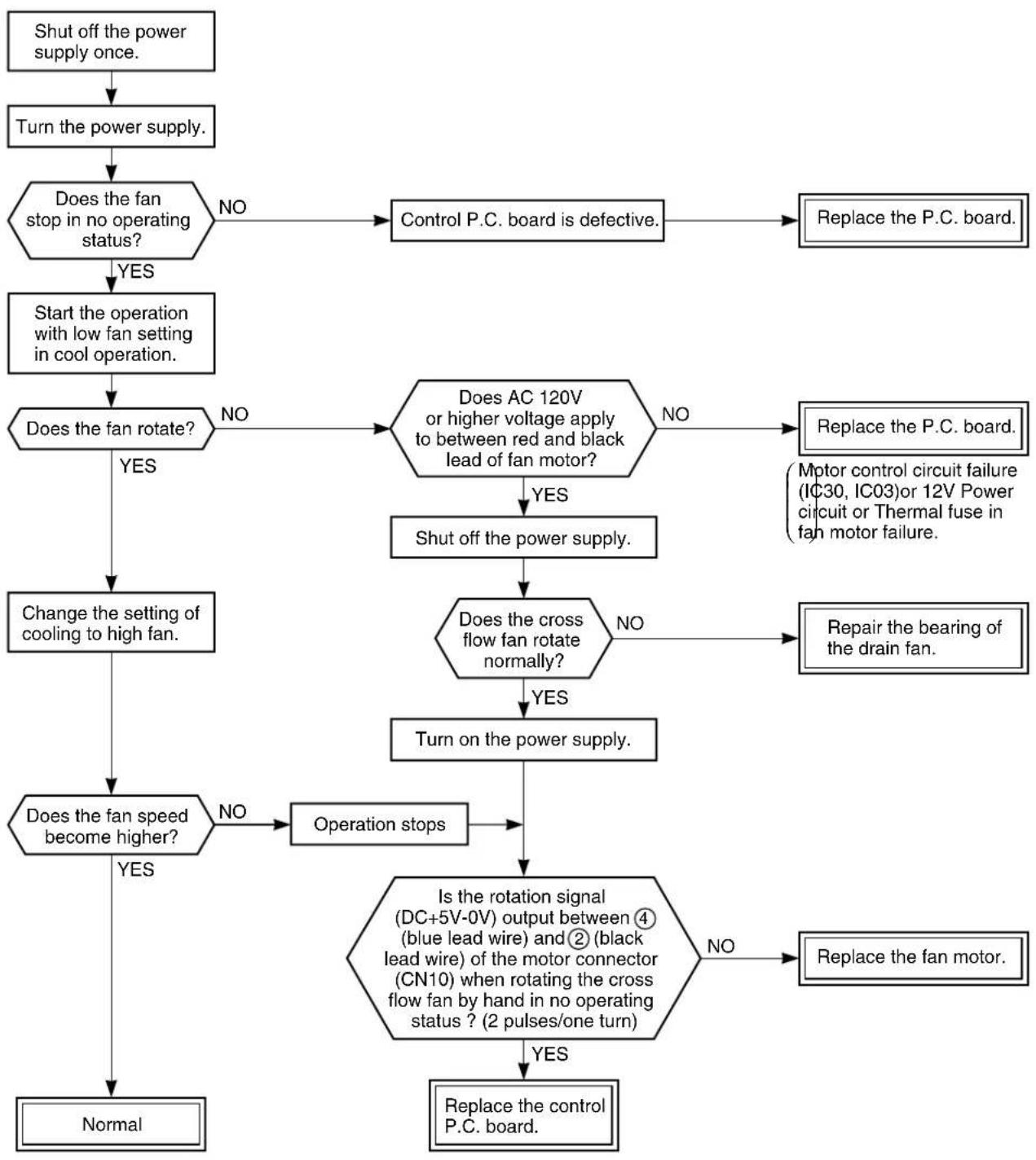
flowchart
graph TD
    A["Shut off the power supply once."] --> B["Turn the power supply."]
    B --> C{Does the fan stop in no operating status?}
    C -->|NO| D["Control P.C. board is defective."]
    D --> E["Replace the P.C. board."]
    C -->|YES| F["Start the operation with low fan setting in cool operation."]
    F --> G{Does the fan rotate?}
    G -->|NO| H{Does AC 120V or higher voltage apply to between red and black lead of fan motor?}
    H -->|NO| I["Replace the P.C. board."]
    H -->|YES| J["Shut off the power supply."]
    J --> K{Does the cross flow fan rotate normally?}
    K -->|NO| L["Repair the bearing of the drain fan."]
    K -->|YES| M["Turn on the power supply."]
    M --> N{Does the fan speed become higher?}
    N -->|NO| O["Operation stops"]
    N -->|YES| P["Normal"]
    O --> Q{Is the rotation signal (DC+5V-0V) output between ④ (blue lead wire) and ② (black lead wire) of the motor connector (CN10) when rotating the cross flow fan by hand in no operating status ? (2 pulses/one turn)}
    Q -->|NO| R["Replace the fan motor."]
    Q -->|YES| S["Replace the control P.C. board."]
*Be sure to disconnect the motor connector CN10 after shut off the power supply, or it will be a cause of damage of the motor.
9-4. How to Check the Remote Control (Including the Indoor P.C. Board)
flowchart
graph TD
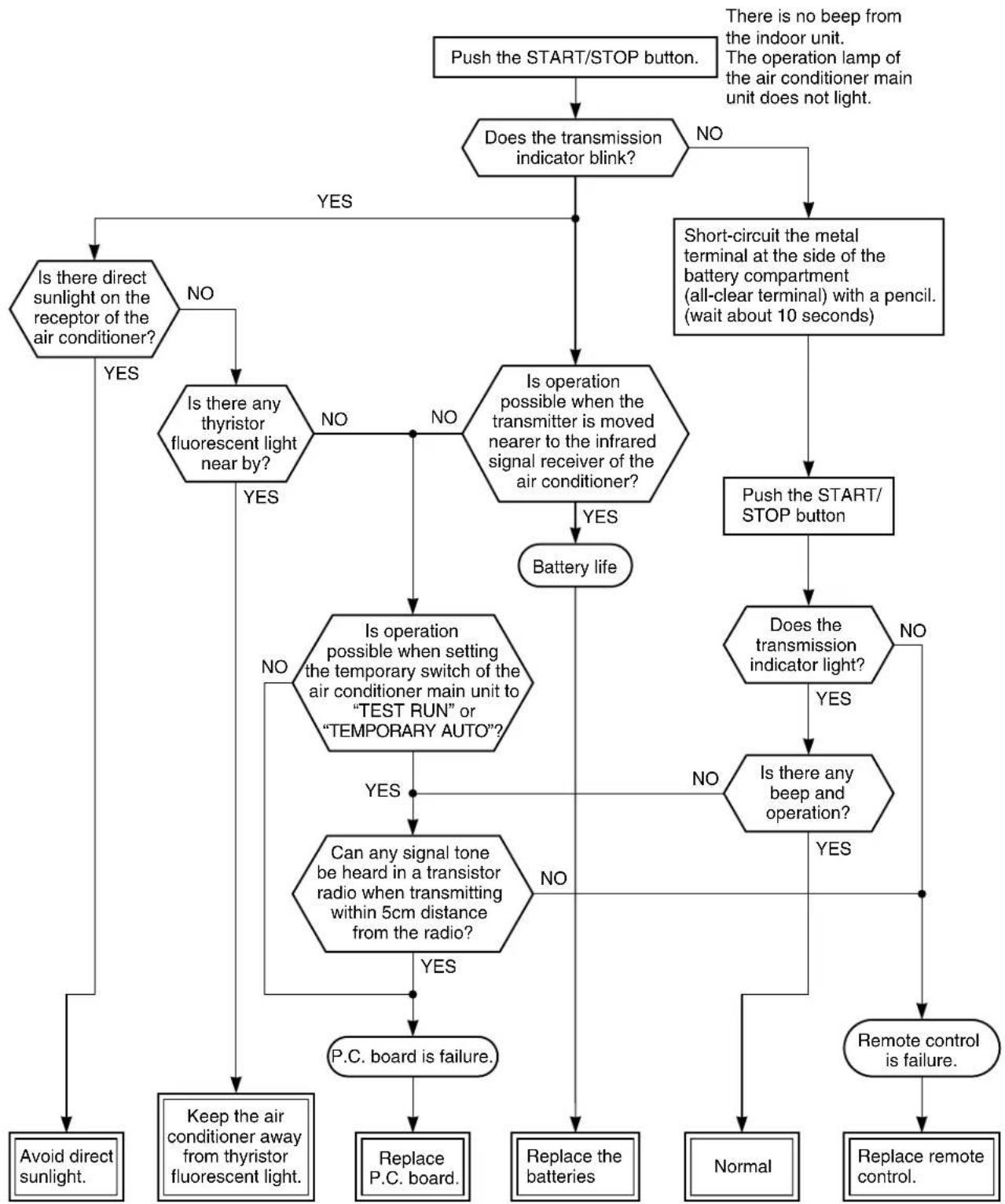
A["Push the START/STOP button."] --> B{Does the transmission indicator blink?}
B -->|NO| C["Short-circuit the metal terminal at the side of the battery compartment (all-clear terminal) with a pencil. (wait about 10 seconds)"]
B -->|YES| D{Is there direct sunlight on the receptor of the air conditioner?}
D -->|YES| E["Avoid direct sunlight."]
D -->|NO| F{Is there any thyristor fluorescent light near by?}
F -->|YES| G["Keep the air conditioner away from thyristor fluorescent light."]
F -->|NO| H{Is operation possible when the transmitter is moved nearer to the infrared signal receiver of the air conditioner?}
H -->|YES| I["Battery life"]
H -->|NO| J{Is operation possible when setting the temporary switch of the air conditioner main unit to "TEST RUN" or "TEMPORARY AUTO"?}
J -->|YES| K["Can any signal tone be heard in a transistor radio when transmitting within 5cm distance from the radio?"]
J -->|NO| L["P.C. board is failure."]
I --> M{Is there any beep and operation?}
M -->|YES| N["Remote control is failure."]
M -->|NO| O["Normal"]
M -->|NO| P["Replace remote control."]
N --> Q["Replace the batteries"]
O --> R["Receive P.C. board."]
P --> S["Receive P.C. board."]
Note: After battery replacement, shortcircuit the metal terminal at the side of the battery compartment (all-clear terminal) with a pencil.
9-4-1. How to Check the P.C. Board
(1) Operating precautions
1) When removing the front panel or the P.C. board, be sure to shut off the power supply.
2) When removing the P.C. board, hold the edge of the P.C. board and do not apply force to the parts.
3) When connecting or disconnecting the connectors on the P.C. board, hold the whole housing. Do not pull at the lead wire.
(2) Inspection procedures
1) When a P.C. board is judged to be defective, check for disconnection, burning, or discoloration of the copper foil pattern or this P.C. board.
2) The P.C. board consists of the following 2 parts
a. Main P.C. board part:
Power relay, indoor fan motor drive circuit and control circuit, C.P.U. and peripheral circuits, buzzer drive circuit and buzzer.
b. Infrared rays receive and indication parts:
Infrared rays receive unit and LED.
(3) Checking procedure
Table 9-4-1
| No. | Procedure Check Point (Symptom) Causes | ||
| 1 | Shut off the power supply and remove the P.C. board assembly from the electronic parts base.Remove the connecting cable from the terminal block. | 1. Is the fuse blown? 1. • Application of sh | ock voltage.• Overload by short-circuit of the parts. |
| 2 | Remove the connector for the motor, and turn the power on.If the OPERATION lamp blinks (0.5 sec. : ON, 0.5 sec. :OFF) when the power turning on, the checking points described as 1-5 of right column are not necessary to perform. | Voltage check1. Between TP1 and TP2(AC 220–240V) (AC 220V)**2. Between + and – of C02(DC 310 ~ 340V)3. Between 12V and GND4. Between 5V and GND | 1. • AC power cord is defective.• Poor contact of the terminal plate.• Miss wiring of the power relay.2. • Capacitor (C01, C15) is defective.• Line filter (L01) is defective.• Resistor (R01) is defective.• Diode (DB01) is defective.3. Q01, IC02, T01, F03 are defective.4. Q01, IC02, T01, F02, Q29, IC03 are defective. |
| 3 | Make the operation status by pushing once the START/STOP button, except the status of [FAN ONLY], [ON TIMER]. | Voltage check1. Voltage of relay coil. (DC 12V)Between pin 10 of IC31 and GNDBetween pin 11 of IC31 and GND2. Between No. 1 and 2 of connecting cable terminal block.(AC 220–240V) (AC 220V)** | 1. Breaking wire of the relay coil, defective relay driver. (IC31)2. Poor contact of relay. |
| 4 | Start the operation with the system which the time of the restart delay timer is shortened. | 1. All indicators light for 3 sec..2. Indicators do not indicate normally after approximate 3 sec.. | Defective indicator, or poor housing assembly. (CN13) |
| 5 | Make the operation status by pressing once the START/STOP button.1. The time of the restart delay timer is shortened.2. Cool operation3. Air volume [AUTO]4. Make the setting temperature lower enough than room temperature.5. Continuous operation. | 1. Compressor does not operate.2. OPERATION lamp blinks. | 1. The temperature of the indoor heat exchanger is abnormally lower.2. Poor contact of the heat exchanger sensor. (The connector is disconnected.) (CN01)3. Heat exchanger sensor, main P.C. board are defective. (Refer to Table 9-4-2 for the judgment of defective resistance values.)4. Main P.C. board is defective. |
| 6 | The status of No. 5 is continued, and make the following condition.1. Heat operation2. Make the setting temperature higher enough than room temperature. | 1. Compressor does not operate.2. OPERATION lamp blinks. | 1. The temperature of the heat exchanger is abnormally high.2. The heat exchanger sensor connector has short-circuit. (CN01)3. The heat exchanger sensor is defective. (Refer to Table 9-4-2 for the judgment of defective resistance values.)4. P.C. board is defective. |
| 7 | Turn the power on after connecting the motor connector.Start the operation with the following condition.1. Operation [Cooling]2. Airflow [High fan]3. Continuous operation | 1. Motor does not rotate. (The key operation is accepted.)2. The motor rotates, but it vibrates too much. | 1. Poor contact of the motor connector.2. P.C. board is defective. |
** for odel RAS-07YKX-T, RAS-10YKX-T
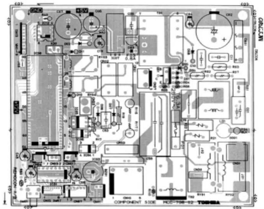
9-4-2. P.C. Board Layout
Top View
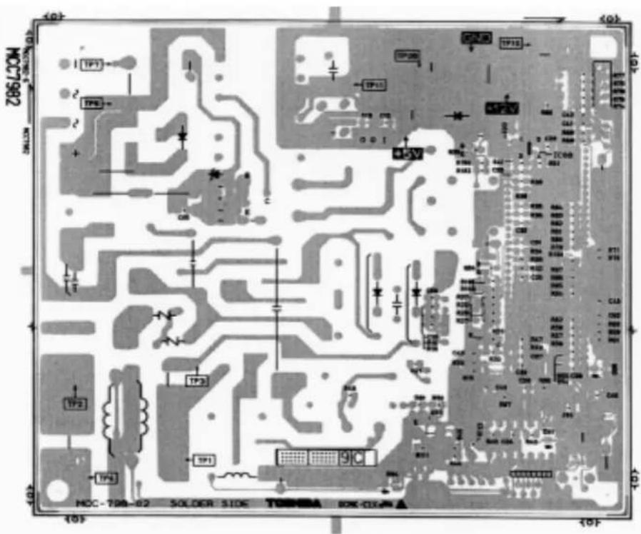
Table 9-4-2 Approximate value of the sensor (thermistor) resistance (TA, TC)
(= kΩ)
| Sensor\Temperature | 0°C | 10°C | 20°C | 25°C | 30°C |
| Themo. Sensor 35,8 20,7 12,6 10,0 7,92 |
9-4-3. How to Reduce the Operation Time of the Anti-Restart Timer
(1) Set the operation mode, temperature, and air flow rate to be applied with the timer short mode.
(2) Push the [CNL] button while keeping [CHK] button pushed. In this case, the check mode is released, and the timer short mode is waited.
(The status is kept even if [CHK] and [CNL] buttons are released.)
(3) Pushing [START/STOP] buttons sends operation code + timer short code.
(4) The timer short mode is released by only a transmission. Therefore, repeat steps from (2) to perform the timer short mode again.
![TEMP. START/STOP AUTO SET FAN MODE ACL CHK ECONO. TIMER ON OFF RSV CNL WC-E1BE [CHK] button [CNL] button](/content/2026/06/1186871/images/7ce853c0803914afd50b0641a9bbf097a8210417b3ec9d41fa3addf1cd33af3c.jpg)
Fig. 9-4-1
10. PART REPLACEMENT
10-1. Indoor Unit
| No. | Part name Procedure | Remarks | |
| 1 | Front panel 1) | After stopping the operation of the air conditioner, be sure to turn off the circuit breaker or disconnect the power plug from the AC wall socket.2) Open the screw caps and remove the two screws fixing the front panel.3) Close the screw caps as they were.4) Open the horizontal louver right below by your finger.5) Open the lower side of front panel until it touches the horizontal louver, and remove it from the indoor unit by turning it.<To assemble the front panel>1) Fix the two screws to secure the front panel.2) Close the screw caps as they were.3) Press four places where are the center, right end, left end and lower portions of the air outlet.4) Check the gap between the front panel and the main unit.If cooling or drying operation is performed without pressing the center of the air outlet, the surface of the front panel may be covered with frost and have a waterdrop. | 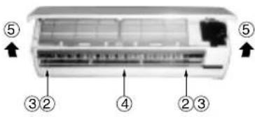 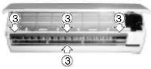 |
| 2 | Electrical part assembly | 1) Perform the process 1 above.2) Remove the electrical part cover by pressing the nail located on upper portion of the electrical part cover.3) Remove the drain guide.4) Remove the screw securing to the end plate of the heat exchanger.5) Remove the connector (3p+3p) for the fan motor and the connector (6p) for the louver motor from the microcomputer assembly.6) After unhooking the electrical part base by pressing the fixing nail located on its lower portion, draw the electrical part base out toward you to remove it from the main unit.7) Pull the TC sensor out from the holder of the heat exchanger.(Keep it with the holder of TC sensor.)8) Dress the connecting cable securely as shown in the right illustration.(Improper dressing will cause water leakage.) |  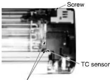 When assembling dress the connecting cable in loop and put it into the drain-pan. When assembling dress the connecting cable in loop and put it into the drain-pan. |
| 3 | Drain-pan assembly | 1) Perform the process 2 above.2) Remove the drain-pan by pressing the four hooks downwards.(Keep it with the drain hose.) | 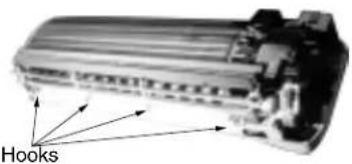 |
| No. | Part name Proced | ure Remarks | |
| 4 | Horizontal grilleNote:The horizontal grille can not be removed without removing the louver motor. | 1) Perform the process 2.2) Remove the screw fixing the louver motor, and remove the louver motor.3) Remove the shaft of the horizontal grille from the drain-pan. | 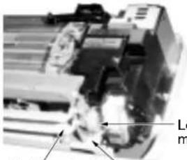 uover motorHorizontal grille Screw uover motorHorizontal grille Screw |
| 5 | Heat exchanger 1) | Perform the process 3.2) Remove the pipe holder from the rear side of main unit by removing the screw.3) Unhook the hooks fixing the left side of the heat exchanger and remove the screw fixing it, then remove the right side of the end plate from the rib fixing the main unit by sliding the heat exchanger slightly to the right side. |  Hooks fixing the heat exchangerShaft bearing base Hooks fixing the heat exchangerShaft bearing base  Screw fixing the heat exchanger Screw fixing the heat exchanger |
| 6 | Cross flow fan 1) | Perform the process 3.2) Loosen the set screw of the cross flow fan.3) Remove the screw fixing the shaft bearing base.4) Lift slightly up the left side of the heat exchanger, and pull the shaft bearing base out left downwards.When assembling it, fix it with the set screw on the position where the gap between the rear plate surface and the left end surface of the cross flow fan is 6~7mm. |   |
| 7 | Shaft bearing 1) | Perform the process 6 above.2) Remove the shaft bearing from the shaft bearing base.<Caution for assembling>If a part of the shaft bearing is protruded from the housing, assemble it after pushing its portion into the correct position in the housing. |  |
| 8 | Fan motor 1) | Perform the process 5 above.2) Perform the process 6 -2) above.3) Remove the left and right motor bands.4) Remove the fan motor after pulling the cross flow fan out sliding it left and right. | Mount the fan motor as shown in figure in the left when assembling.Put the end of lead wire at the portion between two ribs. |
10-2. Microcomputer
RAS-07YKX, RAS-07YK-E, RAS-07YKX-T, RAS-07YK-ES
RAS-10YKX, RAS-10YK-E, RAS-10YKX-T
RAS-11YKX, RAS-10YK-ES, RAS-10YK-HX
| No. | Part name | Procedure | Remarks |
| 1 | Common procedure | 1) Turn the power supply off to stop the operation of air-conditioner, and disconnect the power cord from the AC supply.2) Remove the front panel.Remove the two fixing screws. (∅4 x 14l)3) Remove the electrical part base. | Replace the thermal fuse, terminal block, power cord, microcomputer ass'y and the power supply P.C. board ass'y. |
| 2 | Thermal fuse replacement | 1) Perform the process above.2) Remove terminal cover Up.3) Remove terminal cover Down.(RAS-07YK-E, 10YK-E, 10YK-ES, 07YK-ES only)4) Disconnect the terminal block, connect with the connecting cable from base-E-parts by removing the screws.5) Disconnect the terminal block, connect with the power cord from base E-parts by removing the screws.(RAS-07YK-E, 10YK-E, 10YK-ES, 07YK-ES only)6) Remove the thermal fuse (77°C) from base E-parts. |
10-3. Outdoor Unit
| No. | Part name Procedure | Remark | |
| 1 | Common procedure | 1) Stop the operation of air-conditioner, and disconnect the power cord from the AC supply.2) Remove Electric parts cover.(2-ST1T ∅4 x 10 ℓ)(1-ST1T ∅4 x 10 ℓ:07YA-ES & 10YA-ES only)3) Remove the cord clamp (2-ST2T ∅4 x 12 ℓ) and remove the connecting cable.4) Remove the front cabinet.(7-ST1T ∅4 x 10 ℓ with nylon washer)• Pull the front lower portion toward you, and remove it pulling out upward. | 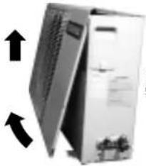 Remove 7-ST1T ∅4 x 10 ℓ Remove 7-ST1T ∅4 x 10 ℓ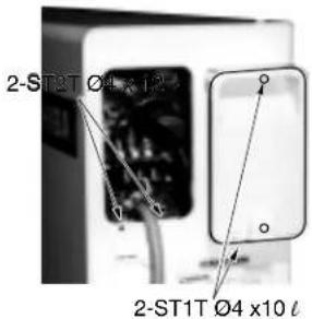 |
| 2 | Capacitor for compressor | 1) Remove the fixing screw of the capacitor band.(1-ST2T ∅4 x 8 ℓ)2) Remove the cable connected to the terminal. | Refer to [Specifications of Electric Parts] in pages 10 and 11. |
| 3 | Capacitor for fan motor | 1) Remove the fixing screw of the capacitor band.(1-ST2T ∅4 x 8 ℓ)2) Remove the cable connected to the terminal. | |
| 4 | Overload relay(Except for 07YA-ES & 10YA-ES) | 1) Perform the process 1 above.2) Remove terminal cover of compressor.3) Remove overload relay holder and pull overload relay up.4) Remove Fustons of leads. | 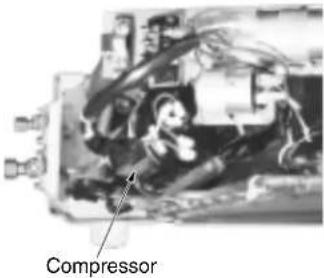 |
11. EXPLODED VIEWS AND PARTS LIST
11-1. Indoor Unit (1)
RAS-07YK-E, RAS-07YK-ES, RAS-10YK-E, RAS-10YK-ES
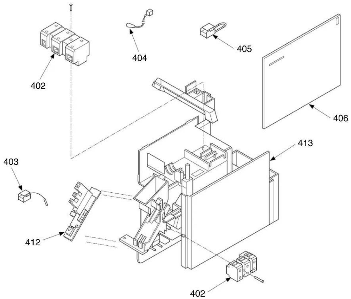
| Location No. No. | Part | Description |
| 402 43 | T60002 Base, Terminal 3P, AC 300V, 20A | |
| 403 43 | T69004 Sensor, Heat Exchanger 10kΩ, 25°C | |
| 404 43 | T69005 Sensor, Thermostat 10kΩ, 25°C | |
| 405 | 43T60061 | Fuse Set, Thermal 77°C |
| Location No. No. | Part | Description |
| 406 43T69055 P.C. Board Assembly, MCC-798 (07YK-E, 07YK-ES) | ||
| 406 43T69054 P.C. Board Assembly, MCC-798 (10YK-E, 10YK-ES) | ||
| 412 43T69031 P.C. Board Assembly, WRS-LED, MCC-766 | ||
| 413 43T61001 Base, E-Parts ABS, Black, UL94-5V | ||
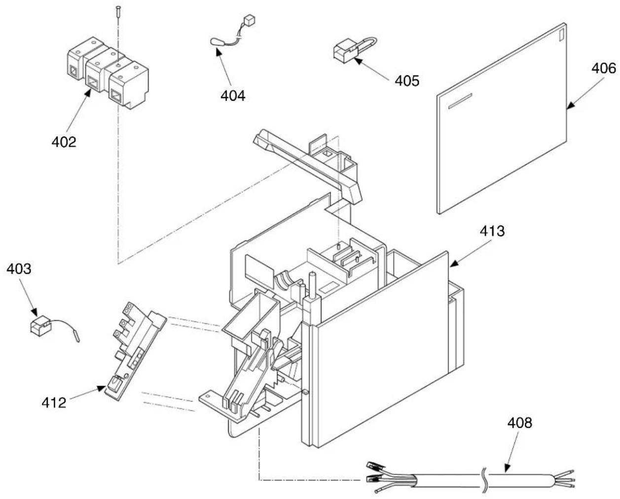
| Location No. No. | Part | Description |
| 402 43T60002Base, Terminal 3P, AC 300V, 20A | ||
| 403 43T69004 Sensor, Heat Exchanger 10kΩ, 25°C | ||
| 404 43T69005 Sensor, Thermostat 10kΩ, 25°C | ||
| 405 43T60301 Fuse Set, Thermal 77°C | ||
| 406 43T69055 P.C. Board Assembly, MCC-798 (07YKX, 07YKX-T) | ||
| Location No. No. | Part | Description |
| 406 43T69054 P.C. Board Assembly, MCC-798 (10YKX, 10YKX-T, 10YK-HX, 11YKX) | ||
| 408 43T60042 Cord, Power (without plug) | ||
| 408 43T60303 Cord, Power (with plug) (10YK-HX only) | ||
| 412 43T69031 P.C. Board Assembly, WRS-LED, MCC-766 | ||
| 413 43T61001 Base, E-Parts ABS, Black, UL94-5V | ||
11-1. Indoor Unit (2)
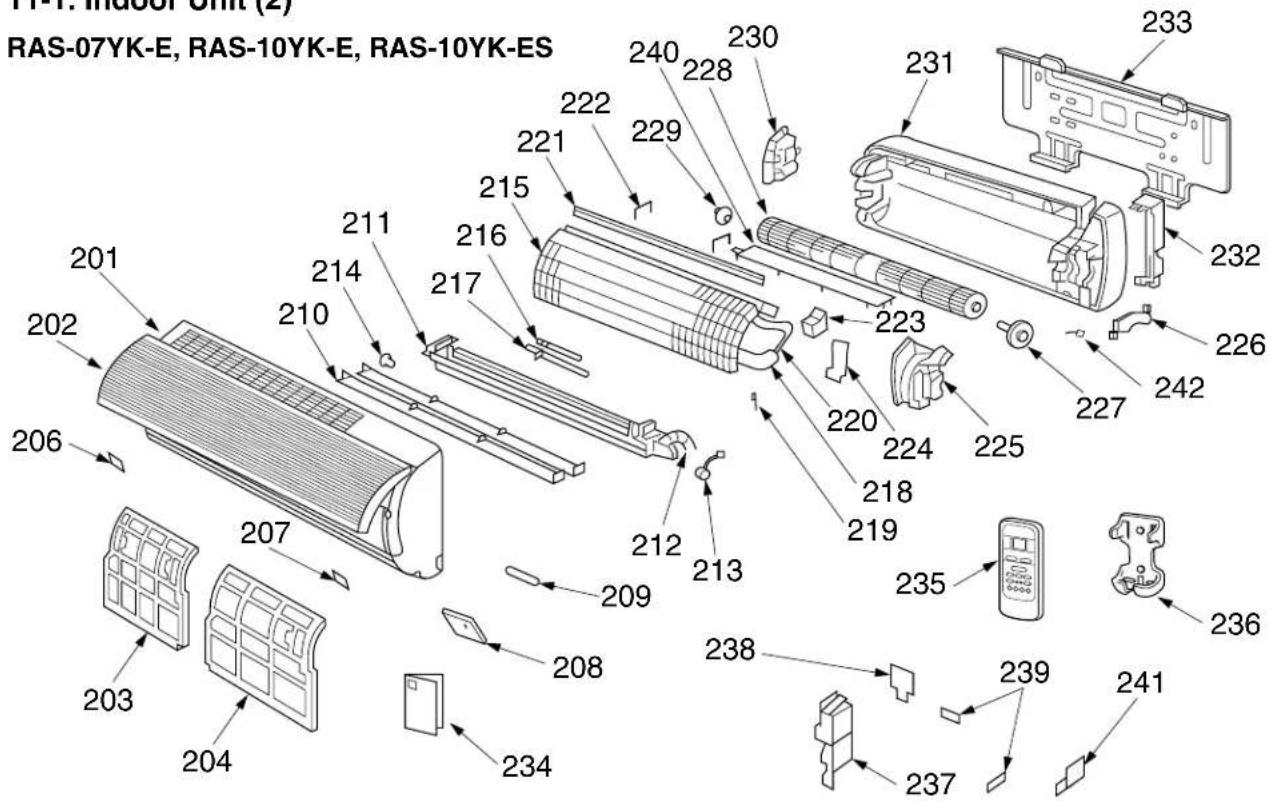
| Location No. | Part | Description |
| 201 | 43T00301 Panel Assembly, Front (07YK-E) | |
| 201 | 43T00302 Panel Assembly, Front (10YK-E) | |
| 201 | 43T00304 Panel Assembly, Front (10YK-ES) | |
| 202 | 43T00044 Grille, Suction | |
| 203 | 43T80001 Air Filter (L) | |
| 204 | 43T80002 Air Filter (R) | |
| 206 | 43T07021 Cap, Screw (L) | |
| 207 | 43T07020 Cap, Screw (R) | |
| 208 | 43T08301 Panel, Control (07YK-E) | |
| 208 | 43T08302 Panel, Control (10YK-E) | |
| 208 | 43T08304 Panel, Control (10YK-ES) | |
| 209 | 43T19004 Filter, Accepted Signal | |
| 210 | 43T09035 Louver Ass'y, Horizontal for Service | |
| 211 | 43T09304 Louver Ass'y (07YK-E) | |
| 211 | 43T09303 Louver Ass'y (10YK-E, 10YK-ES) | |
| 212 | 43T70301 Hose Ass'y, Drain | |
| 213 | 43T21302 Motor, Stepping | |
| 214 | 43T07001 Bushing | |
| 215 | 43T44301 Refrigeration Cycle Ass'y (07YK-E) | |
| 215 | 43T44003 Refrigeration Cycle Ass'y (10YK-E) | |
| 215 | 43T44302 Refrigeration Cycle Ass'y (10YK-ES) | |
| 216 | 43T47006 Pipe, Delivery | |
| 217 | 43T47305 Pipe, Suction (07YK-E) |
| Location No. | Part | Description |
| 217 | 43T47005 Pipe, Suction (10YK-E, 10YK-ES) | |
| 218 | 43T49007 Pipe, Shield | |
| 219 | 43T19003 Holder, Sensor | |
| 220 | 43T49003 Spring (10YK-E, 10YK-ES) | |
| 221 | 43T49028 Plate, EVA-SEAL | |
| 222 | 43T49023 Holder, Plate EVA-SEAL | |
| 223 | 43T49004 Rubber, Sound Insulation | |
| 224 | 43T79002 Guide, Drain | |
| 225 | 43T39002 Band, Motor (L) | |
| 226 | 43T39001 Band, Motor (R) | |
| 227 | 43T21301 Motor, Fan | |
| 228 | 43T20007 Fan, Cross Flow | |
| 229 | 43T22002 Bearing | |
| 230 | 43T39003 Base, Bearing | |
| 231 | 43T03001 Plate, Rear | |
| 232 | 43T07002 Holder, Pipe | |
| 233 | 43T82001 Plate, Installation | |
| 234 | 43T85301 Owner's Manual | |
| 235 | 43T69032 Remote Control, Wireless | |
| 236 | 43T63002 Holder, Remote Control | |
| 237 | 43T62008 Cover, E-Parts | |
| 238 | 43T62002 Cover, Up, Terminal | |
| 239 | 43T62003 Clamp, Cord | |
| 240 | 43T39010 Guide, Drain, Up | |
| 241 | 43T62005 Cover, Down, Terminal | |
| 242 | 43T60305 Connector, fan motor |
RAS-07YK-ES
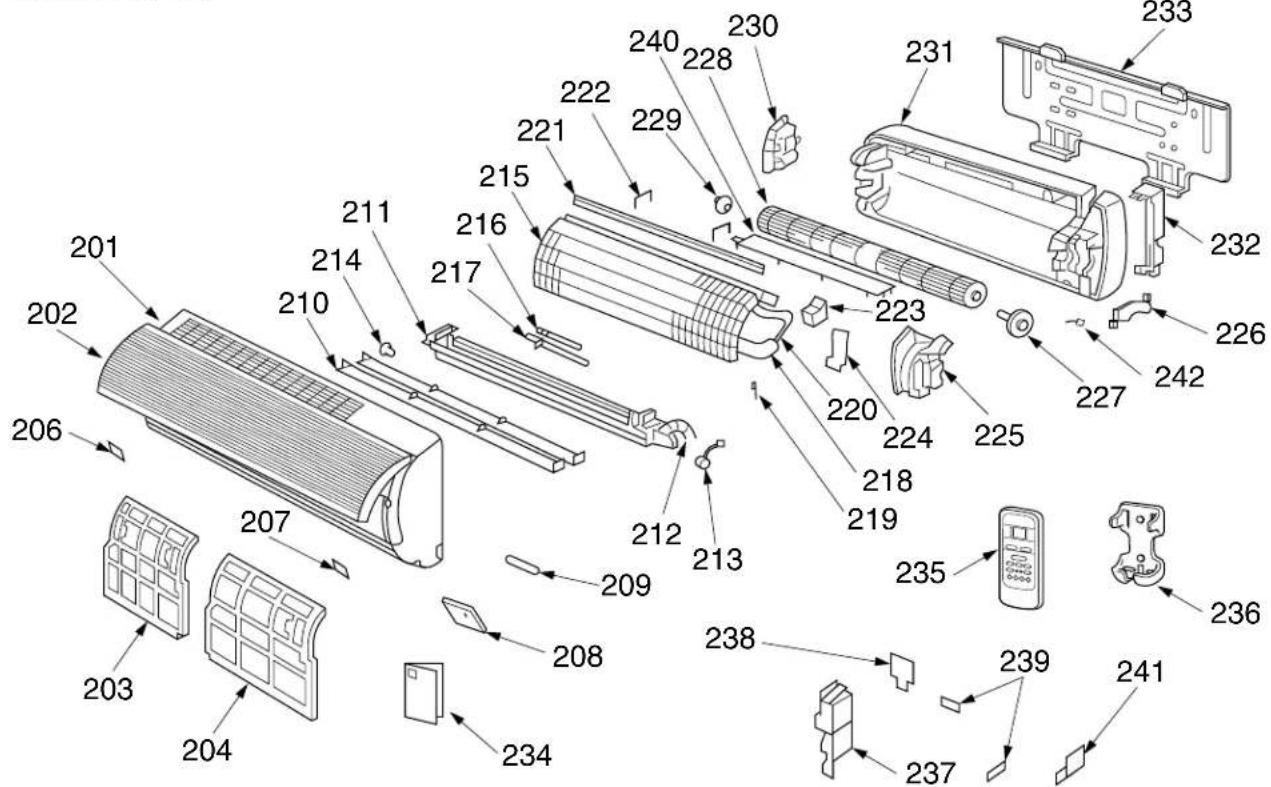
| Location No. No. | Part | Description |
| 201 | 43T00324 | Panel Assembly, Front (07YK-ES) |
| 202 | 43T00044 | Grille, Suction |
| 203 | 43T80001 | Air Filter (L) |
| 204 | 43T80002 | Air Filter (R) |
| 206 | 43T07021 | Cap, Screw (L) |
| 207 | 43T07020 | Cap, Screw (R) |
| 208 | 43T08331 | Panel, Control (07YK-ES) |
| 209 | 43T19004 | Filter, Accepted Signal |
| 210 | 43T09035 | Louver Ass'y, Horizontal for Service |
| 211 | 43T09307 | Louver Ass'y (07YK-ES) |
| 212 | 43T70301 | Hose Ass'y, Drain |
| 213 | 43T21302 | Motor, Stepping |
| 214 | 43T07001 | Bushing |
| 215 | 43T44307 | Refrigeration Cycle Ass'y (07YK-ES) |
| 216 | 43T47006 | Pipe, Delivery |
| 217 | 43T47305 | Pipe, Suction (07YK-ES) |
| 218 | 43T49007 | Pipe, Shield |
| 219 | 43T19003 | Holder, Sensor |
| 221 | 43T49028 | Plate, EVA-SEAL |
| 222 | 43T49023 | Holder, Plate EVA-SEAL |
| 223 | 43T49004 | Rubber, Sound Insulation |
| 224 | 43T79002 | Guide, Drain |
| 225 | 43T39002 | Band, Motor (L) |
| 226 | 43T39001 | Band, Motor (R) |
| 227 | 43T21301 | Motor, Fan |
| Location No. | Part No. | Description |
| 228 | 43T20007 | Fan, Cross Flow |
| 229 | 43T22002 | Bearing |
| 230 | 43T39003 | Base, Bearing |
| 231 | 43T03001 | Plate, Rear |
| 232 | 43T07002 | Holder, Pipe |
| 233 | 43T82001 | Plate, Installation |
| 234 | 43T85301 | Owner's Manual |
| 235 | 43T69032 | Remote Control, Wireless |
| 236 | 43T63002 | Holder, Remote Control |
| 237 | 43T62008 | Cover, E-Parts |
| 238 | 43T62002 | Cover, Up, Terminal |
| 239 | 43T62003 | Clamp, Cord |
| 240 | 43T39010 | Guide, Drain, Up |
| 241 | 43T62005 | Cover, Down, Terminal |
| 242 | 43T60305 | Connector, fan motor |
RAS-07YKX, RAS-07YKX-T, RAS-10YKX, RAS-10YKX-T, RAS-11YKX, RAS-10YK-HX
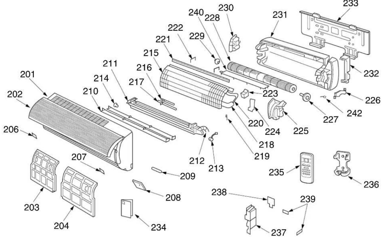
| Location No. | Part | Description |
| 201 | 43T00310 | Panel Assembly, Front (07YKX) |
| 201 | 43T00311 | Panel Assembly, Front (07YKX-T) |
| 201 | 43T00312 | Panel Assembly, Front (10YKX) |
| 201 | 43T00313 | Panel Assembly, Front (10YKX-T) |
| 201 | 43T00314 | Panel Assembly, Front (11YKX) |
| 201 | 43T00315 | Panel Assembly, Front (10YK-HX) |
| 202 | 43T00044 | Grille, Suction |
| 203 | 43T80001 | Air Filter (L) |
| 204 | 43T80002 | Air Filter (R) |
| 206 | 43T07021 | Cap, Screw (L) |
| 207 | 43T07020 | Cap, Screw (R) |
| 208 | 43T08310 | Panel, Control (07YKX) |
| 208 | 43T08311 | Panel, Control (07YKX-T) |
| 208 | 43T08312 | Panel, Control (10YKX) |
| 208 | 43T08313 | Panel, Control (10YKX-T) |
| 208 | 43T08314 | Panel, Control (11YKX) |
| 208 | 43T08315 | Panel, Control (10YK-HX) |
| 209 | 43T19004 | Filter, Accepted Signal |
| 210 | 43T09035 | Louver Ass'y, Horizontal for Service |
| 211 | 43T09301 | Louver Ass'y (07YKX, 07YKX-T) |
| 211 | 43T09302 | Louver Ass'y (10YKX, 11YKX, 10YKX-T) |
| 211 | 43T09303 | Louver Ass'y (10KX-HX) |
| 212 | 43T70301 | Hose Ass'y, Drain |
| 213 | 43T21302 | Motor, Stepping |
| 214 | 43T07001 | Bushing |
| 215 | 43T44301 | Refrigeration Cycle Ass'y (07YKX, 07YKX-T) |
| 215 | 43T44003 | Refrigeration Cycle Ass'y (10YKX, 10YK-HX, 11YKX) |
| 215 | 43T44023 | Refrigeration Cycle Ass'y (10YKX-T) |
| 216 | 43T47006 | Pipe, Delivery |
| 217 | 43T47305 | Pipe, Suction (07YKX, 07YKX-T) |
| Location No. | Part | Description |
| 217 | 43T47005 Pipe, Suction(10YKX, 10YK-HX, 11YKX) | |
| 217 | 43T47304 Pipe, Suction (10YKX-T) | |
| 218 | 43T49007 Pipe, Shield | |
| 218 | 43T49010 Pipe, Shield (10YKX-T only) | |
| 219 | 43T19003 Holder, Sensor | |
| 220 | 43T49003 Spring (10YKX, 11YKX, 10YK-HX) | |
| 220 | 43T49009 Spring (10YKX-T) | |
| 221 | 43T49028 Plate, EVA-SEAL | |
| 222 | 43T49023 Holder, Plate EVA-SEAL | |
| 223 | 43T49004 Rubber, Sound Insulation | |
| 224 | 43T79002 Guide, Drain | |
| 225 | 43T39002 Band, Motor (L) | |
| 226 | 43T39001 Band, Motor (R) | |
| 227 | 43T21301 Motor, Fan | |
| 228 | 43T20007 Fan, Cross Flow | |
| 229 | 43T22002 Bearing | |
| 230 | 43T39003 Base, Bearing | |
| 231 | 43T03001 Plate, Rear | |
| 232 | 43T07002 Holder, Pipe | |
| 233 | 43T82001 Plate, Installation | |
| 234 | 43T85303 Owner's Manual(07YKX, 10YKX, 11YKX) | |
| 234 | 43T85304 Owner's Manual(07YKX-T, 10YKX-T) | |
| 234 | 43T85305 Owner's Manual(10YK-HX) | |
| 235 | 43T69032 Remote Control, Wireless | |
| 236 | 43T63002 Holder, Remote Control | |
| 237 | 43T62008 Cover, E-Parts | |
| 238 | 43T62002 Cover, Up, Terminal | |
| 239 | 43T62003 Clamp, Cord | |
| 240 | 43T39010 Guide, Drain, Up | |
| 242 | 43T60305 Connector, fan motor |
11-2. Outdoor Unit
RAS-07YA-E, RAS-10YA-E, RAS-10YA-HX
7: CAPILLARY TUBE
23 : NUT, FLAT WASHER (07YA-E)
24: DRYER (10YA-E, 10YA-HX)
| Location No. No. | Part | Description |
| 1 43T19001 Guard, Fan2 43T20001 Fan, Propeller3 43005037 Cabinet, Front4 43T43005 Condenser (07YA-E)4 43T43003 Condenser (10YA-E, 10YA-HX)5 43T62007 Cover, E-Parts6 43T00032 Cabinet, Back7 43T47008 Tube, Capillary8 43T46017 Valve, Packed 9,529 43T47021 Bonnet10 43T46016 Valve, Packed 6,3511 43T47020 Bonnet12 43021001 Motor, Fan, UE6-21SJ5P13 43T47001 Nut, Flange14 43T19005 Handle15 43T49001 Rubber, Cushion |
| Location No. No. | Part | Description |
| 16 43T19002 Stopper, Guard | ||
| 17 43T63001 Holder, OL-Relay (07YA-E) | ||
| 18 43T54302 Relay, Over Load (07YA-E) | ||
| 18 43T54303 Relay, Over Load(10YA-E, 10YA-HX) | ||
| 19 43T41304 Compressor, PH80T1-4C(07YA-E) | ||
| 19 43T41405 Compressor, 2PS146D5AB02(10YA-E, 10YA-HX) | ||
| 20 43055470 Capacitor, 15μF 400V(07YA-E only) | ||
| 20 43055483 Capacitor, 25μF 400V | ||
| 21 43T55001 Capacitor, 1,5μF 500V | ||
| 22 43T60006 Base, Terminal , 3P | ||
| 23 43T97001 Nut, Flat Washer (07YA-E) | ||
| 24 43045073 Dryer |
| Location No. | Part No. | Description |
| 1 | 43T19001 | Guard, Fan |
| 2 | 43T20001 | Fan, Propeller |
| 3 | 43005037 | Cabinet, Front |
| 4 | 43T43302 | Condenser |
| 5 | 43T62007 | Cover, E-Parts |
| 6 | 43T00032 | Cabinet, Back |
| 7 | 43T47318 | Tube, Capillary |
| 8 | 43T46301 | Valve, Packed 9,52 |
| 9 | 43T47021 | Bonnet |
| 10 | 43T46304 | Valve, Packed 6,35 |
| 11 | 43T47020 | Bonnet |
| Location No. | Part No. | Description |
| 12 | 43021928 | Motor, Fan, HF-240-20A |
| 13 | 43T47001 | Nut, Flange |
| 14 | 43T19005 | Handle |
| 15 | 43T49001 | Rubber, Cushion |
| 16 | 43T19002 | Stopper, Guard |
| 17 | 43T41309 | Compressor, PA79X1T-4FZ5 |
| 18 | 43055470 | Capacitor, 15MFD, 400V |
| 19 | 43T55009 | Capacitor, PLASTIC- FILM |
| 20 | 43T60006 | Terminal-3L |
RAS-10YA-ES
| Location No. No. | Part | Description |
| 1 43 | T19001 Guard, Fan | |
| 2 43 | T20001 Fan, Propeller | |
| 3 43 | 005037 Cabinet, Front | |
| 4 43 | T43302 Condenser | |
| 5 43 | 062193 Cover, E-Parts | |
| 6 43 | 005038 Cabinet, Back | |
| 7 43 | T47007 Tube, Capillary | |
| 8 43 | T46011 Valve, Packed 9,52 | |
| 9 43 | T47021 Bonnet | |
| 10 43 | T46010 Valve, Packed 6,35 | |
| 11 43 | T47020 Bonnet |
| Location No. No. | Part | Description |
| 12 43 | 021001 Motor, Fan, UE6-21SJ5P | |
| 13 43 | T47001 Nut, Flange | |
| 14 43 | T19005 Handle | |
| 15 43 | T49001 Rubber, Cushion | |
| 16 43 | T19002 Stopper, Guard | |
| 17 43 | T41302 Compressor, PA98X1T-4FZ | |
| 18 43 | 055483 Capacitor, 25μF 400V | |
| 19 43 | T55001 Capacitor, 1,5μF 500V | |
| 20 43 | T60006 Base, Terminal , 3P | |
| 21 43 | T45004 Dryer | |
| 22 43 | T97001 Nut, Flat Washer |
RAS-07YAX, RAS-07YAX-T, RAS-10YAX, RAS-10YAX-T, RAS-11YAX
| Location No. No. | Part | Description |
| 1 43T19001 Guard, Fan2 43T20001 Fan, Propeller3 43005037 Cabinet, Front4 43T43005 Condenser (07YAX, 07YAX-T)4 43T43003 Condenser (10YAX, 11YAX)4 43T43022 Condenser (10YAX-T)5 43T62007 Cover, E-Parts6 43T00032 Cabinet, Back7 43T47008 Tube, Capillary8 43T46017 Valve, Packed 9,529 43T47021 Bonnet10 43T46016 Valve, Packed 6,3511 43T47020 Bonnet12 43021928 Motor, Fan, UE6-21AJ5P(07YAX, 07YAX-T, 10YAX, 11YAX)12 43021981 Motor, Fan, UE6-31C5P(10YAX-T)13 43T47001 Nut, Flange14 43T19005 Handle15 43T49001 Rubber, Cushion |
| Location No. No. | Part | Description |
| 16 43 | T19002 Stopper, Guard | |
| 17 43 | T63001 Holder, OL-Relay(07YAX, 07YAX-T, 10YAX) | |
| 18 43 | T54302 Relay, Over Load(07YAX, 07YAX-T) | |
| 18 43 | T54303 Relay, Over Load(10YAX, 10YAX-T, 11YAX) | |
| 19 43 | T41304 Compressor, PH80T1-4C(07YAX, 07YAX-T) | |
| 19 43 | T41402 Compressor, PH102T1-4C(10YAX) | |
| 19 43 | T41409 Compressor, RM5510GNE92(10YAX-T) | |
| 19 43 | T41405 Compressor, 2PS146D5AB02(11YAX) | |
| 20 43 | 055470 Capacitor, 15μF 400V(07YAX, 07YAX-T) | |
| 20 43 | T55013 Capacitor, 25μF 440V | |
| 21 43 | T55022 Capacitor, 1,5μF 500V | |
| 22 43 | T60006 Base, Terminal , 3P | |
| 23 43 | T97001 Nut, Flat Washer (07YAX, 07YAX-T) | |
| 24 43 | 045073 Dryer |
TOSHIBA CARRIER (THAILAND) CO., LTD.
144/9 MOO 5, BANGKADI INDUSTRIAL PARK, TIVANON ROAD, TAMBOL BANGKADI, AMPHUR MUANG, PATHUMTHANI 12000, THAILAND.

- CONTENTS
- SPECIFICATIONS
- Notes: \*2 CHARGELESS
- CONSTRUCTION VIEWS
- 2-1.Indoor Unit
- 2-2. Outdoor Unit
- SPECIFICATIONS OF ELECTRICAL PARTS
- 4-2. Outdoor Unit
- OPERATION DESCRIPTIONS
- 7-1. FAN ONLY Operation (The Remote Control MODE Button is Set to the FAN ONLY Operation)
- (MODE of the remote control : FAN ONLY)
- 7-2. COOL Operation
- (MODE of the remote control : COOL)
- 7-2-1. Louver Control
- Vertical air flow louvers
- Swing
- 7-3. DRY Operation
- (MODE of the remote control : DRY)
- 7-4. AUTO Operation
- (MODE of the remote control : AUTO)
- 7-4-1. Temporary Auto
- 7-5. ECONO. Mode
- 7-5-1. Cooling
- 7-6. Low-Temperature Limit Control (Cooling Operation)
- 7-7. Auto Restart Function
- INFORMATION
- 7-7-1. How to Set the Auto Restart
- 7-7-2. How to Cancel the Auto Restart
- 7-7-3. In Case of Power Failure during the Timer Operation
- INSTALLATION PROCEDURE
- 8-1. Safety Cautions
- For general public use
- CAUTION
- DANGER
- WARNING
- UK Plugs and Sockets etc (Safety) Regulations 1994 SI Number 1768
- 8-2. Installation Diagram of Indoor and Outdoor Units
- 8-3. Installation
- 8-3-1. Optional Parts
- Others
- 8-4. Indoor Unit
- ◆ Installation place
- 8-4-1. Cutting a Hole and Mounting Installation Plate
- NOTE :
- 8-4-2. Electrical Work
- 8-4-3. Wiring Connection
- IMPORTANT
- How to open the screw cap
- Wiring of the connecting cable can be carried out without removing of the front panel.
- 8-4-4. Piping and Drain Hose Installation
- Bend the connection pipe within a radius of 30 mm.
- 8-4-5. Indoor Unit Installation
- 8-4-6. Drainage
- 8-5. Outdoor Unit
- Installation place
- 8-5-1. Refrigerant Piping Connection
- 8-5-2. Vacuum Pumping
- Differences in Port Size between Conventional R22 and R410A
- AIR PURGE
- 8-5-3. Wiring Connection
- 8-6. Others
- 8-6-1. Gas Leak Test
- 8-6-2. Test Operation
- 8-6-3. Auto Restart Setting
- TROUBLESHOOTING CHART
- TROUBLESHOOTING PROCEDURES :
- 9-1. What to be Prechecked First
- 9-1-1. Power Supply Voltage
- 9-1-2. Incorrect Cable Connection between Indoor and Outdoor Units
- 9-1-3. Misleading but Good Operations (Program Controlled Operation)
- 9-2. Primary Judgement of Trouble Sources
- 9-2-1. Role of Indoor Unit Controller
- 9-2-2. Display of Abnormalities and Judgement of the Abnormal Spots
- Judgement from defective operation or abnormal operation
- Self-diagnosis with remote control
- [ METHOD]
- [ To release the servicing check ]
- 9-3. Troubleshooting Flowcharts
- 9-3-1. Power can not be Turned on (No Operation at All)
- 9-3-2. Power can not be Turned on after Replacing Indoor P.C. Board
- 9-3-6. Only the Indoor Fan does not Operate
- 9-4-1. How to Check the P.C. Board
- Operating precautions
- Inspection procedures
- a. Main P.C. board part:
- b. Infrared rays receive and indication parts:
- Checking procedure
- 9-4-3. How to Reduce the Operation Time of the Anti-Restart Timer
- PART REPLACEMENT
- 10-2. Microcomputer
- 10-3. Outdoor Unit
- EXPLODED VIEWS AND PARTS LIST
- 11-1. Indoor Unit (1)
- 11-2. Outdoor Unit
- RAS-07YA-E, RAS-10YA-E, RAS-10YA-HX
- TOSHIBA CARRIER (THAILAND) CO., LTD.
Brand : TOSHIBA
Model : RAS-10YA-HX
Category : Air conditioner