
DHD694XE1 - Range hood DE DIETRICH - Free user manual and instructions
Find the device manual for free DHD694XE1 DE DIETRICH in PDF.

| Product type | Range hood |
| Brand | DE DIETRICH |
| Model | DHD694XE1 |
| Motor power | 370 W |
| Supply voltage | 230-240 V single-phase |
| Lighting | 3 halogen bulbs of 20 W |
| Gross weight | 39.5 kg |
| Net weight | 34.5 kg |
| Minimum distance to cooking surface | 65 cm |
| Number of speeds | 4 |
| Control | Mechanical switches + infrared remote control |
| Timer | Yes (automatic stop after 10 min) |
| Grease filters | 2 washable metal filters |
| Charcoal filter (optional) | Model AH4063-U1, replace every 6 months |
| Grease collection trays | 2 removable trays |
| Installation modes | Recirculation or extraction |
| Insulation class | I (requires grounding) |
| Power cord | 150 cm with plug |
| Grease filter maintenance | Every 2 months, hand wash or dishwasher |
| Reference | DHD694XE1 |
Frequently Asked Questions - DHD694XE1 DE DIETRICH
User questions about DHD694XE1 DE DIETRICH
0 question about this device. Answer the ones you know or ask your own.
Ask a new question about this device
Download the instructions for your Range hood in PDF format for free! Find your manual DHD694XE1 - DE DIETRICH and take your electronic device back in hand. On this page are published all the documents necessary for the use of your device. DHD694XE1 by DE DIETRICH.
USER MANUAL DHD694XE1 DE DIETRICH
The distance between the supporting surface for the cooking vessels on the hob and the lower part of the hood must be at least 65 cm. If the instructions for installation for the hob specify a greater distance, this has to be taken into account.
The air collected must not be conveyed into a duct used to blow off smokes from appliances fed with an energy other than electricity (central heating systems, thermosiphons, water-heaters, etc.).
Comply with the official instructions provided by the competent authorities in merit when installing the disposal duct. In addition, exhaust air should not be discharged into a wall cavity, unless the cavity is designed for that purpose.
The room must be well aerated in case a hood and some other heat equipment fed with an energy other than electricity (gas, oil, coal heaters, etc) operate at the same time.
In fact the intake hood, disposing of air, could create a vacuum in the room. The vacuum should not exceed 0,04mbar. This prevents the gas exhausted by the heat source from being intaken again. It is therefore advisable to ensure the room contains air taps able to ensure a steady flow of fresh air.
Check the data label inside the appliance; if the symbol (回) is printed, read the following: this appliance has such technical particulars that it belongs to class II insulation, therefore it must not be earthed.
The following warning is valid in the United Kingdom only: in case your cable is not furnished with a plug, read the following instructions; as the colours of the wires in the mains lead of this appliance may not correspond with the coloured markings identifying the terminals in your plug, proceed as follows: – the wire which is coloured blue must be connected to the terminal which is marked with the letter N or coloured black; – the wire which is coloured brown must be connected to the terminal which is marked with the letter L or coloured red. – terminal of a three-pin plug.
Check the data label inside the appliance; if the symbol (☑) is NOT printed, read the following: ATTENTION: This appliance must be earthed. When making the electrical connections, check that the current socket has a ground connection.
The following warning is valid in the United Kingdom only: in case your cable is not furnished with a plug, read the following instructions; as the colours of the wires in the mains lead of this appliance may not correspond with the coloured markings identifying the terminals in your plug, proceed as follows: – the wire which is coloured green and yellow must be connected to the terminal in the plug which is marked with the letter E or by the earth symbol [1±] , or coloured green or green and yellow; – the wire which is coloured blue must be connected to the terminal which is marked with the letter N or coloured black; – the wire which is coloured brown must be connected to the terminal which is marked with the letter L or coloured red.
When making the electrical connections, check that the voltage values correspond to those indicated on the data plate inside the appliance itself. In case your appliance is not furnished with a non separating flexible cable and has no plug, or has not got any other device ensuring omnipolar disconnection from the electricity main, with a contact opening distance of at least 3mm , such separating device ensuring disconnection from the main must be included in the fixed installation. If your unit features a power lead and plug, position this so the plug is accessible.
Always switch off the electricity supply before carrying out any cleaning or servicing operations on the appliance.
ATTENTION: This appliance must be grounded.
USE
Avoid using materials which could cause spurts of flame (flambées) near the appliance.
When frying, take particular care to prevent oil and grease from catching fire. Already used oil is especially dangerous in this respect. Do not use uncovered electric grates.
To avoid possible risks of fire always comply with the indicated instructions when cleaning anti-grease filters and when removing grease deposits from the appliance.
MAINTENANCE
Thorough servicing guarantees correct and long-lasting operation.
Any fat deposits should be removed from the appliance periodically depending on amount of use (at least every 2 months). Avoid using abrasive or corrosive products. To clean painted appliances on the outside, use a cloth dipped in lukewarm water and neutral detergent. To clean steel, copper or brass appliances on the outside, it is always best to use specific products, following the instructions on the products themselves. To clean the inside of the appliance, use a cloth (or brush) dipped in denatured ethyl alcohol.
DESCRIPTION OF THE APPLIANCE
The description and characteristics shown in this document are for information only and not obligatory. Indeed, we reserve the right to carry out any modification or improvement of the quality of certain of our products without prior notice.
As with all hoods, these apparatuses can be installed in either filtering version or suction version.
In the Filtering version (Fig. 1), the air and vapours conveyed by the appliance are depurated by charcoal filter and recirculated around the room. ATTENTION: Using the hood as a filtering one it is necessary to use the charcoal filter that purifies the air sent back into the room.
In the Ducting version (Fig. 2), cooking vapours and odours are conveyed straight outside by a disposal duct which passes through the wall/ceiling. Use of charcoal filter is therefore unnecessary.
Decide at the beginning which type of installation to adopt.
Your apparatus is supplied in the filtering version so that if you want to install the apparatus in the suction version you must remove the charcoal filter.
This apparatus conforms to the 16.08.89 regulation relating to the limitation of radio-electric disturbances (EC Directive n./ 6.889 modified by the EC Directive 8/.308.).
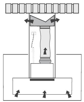
Fig. 1
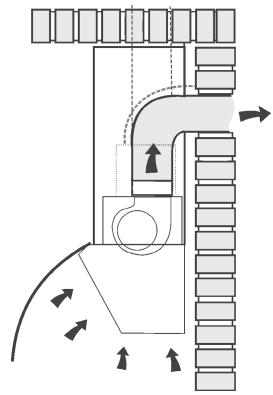
Fig. 2
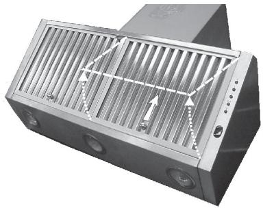
Fig. 3
INSTALLATION
It is advisable to entrust the installation operations to specialised personnel.
Read carefully the indications in the paragraph "IMPORTANT" at page 10 of the instruction booklet.
- Before proceeding with the installation operations, remove the grease filters to make it easier to handle the hood: grip the knob and push it towards the opposite side of the filter and turn the filter outwards (Fig. 3).
- Arrange the electrical power supply within the decorative flue dimensions.
- Should you install the ducting version, prepare the air vent hole and duct.
For optimal conditions in the ducting versions, use an air exhaust pipe with
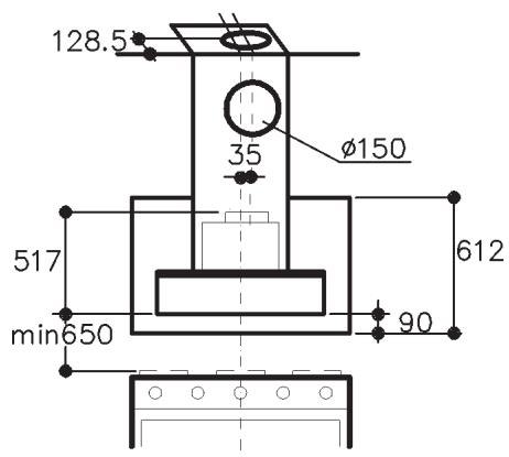
the minimum indispensable length, the least possible number of elbows (maximum elbow angle: 90^ ), certified materials (according to the country), and an as smooth as possible inside. It is also recommended to avoid drastic changes in the pipe cross-section (diameter: 150~mm ). Consider that the air vent of the hood is not on the longitudinal axis but is offset by 35~mm to the right - see dimensions in Fig. 17.
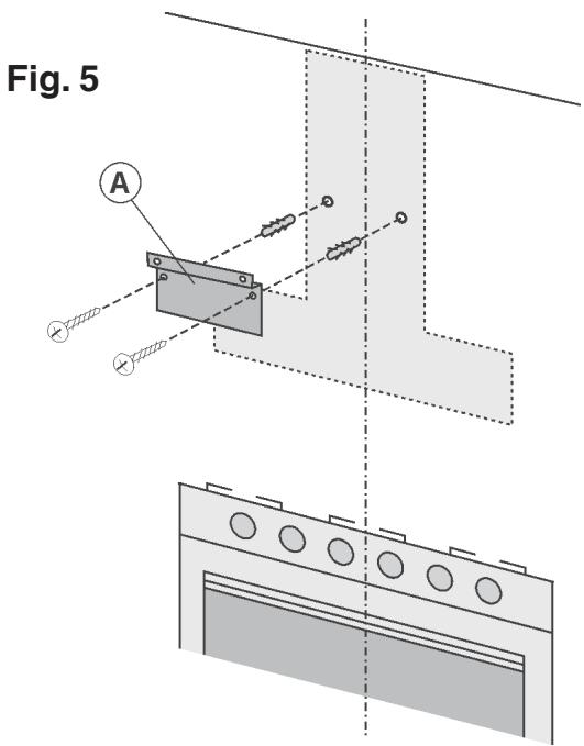
- Fixing to the wall: Draw a line on the wall along the vertical axis of the hob. Mark the first 2 holes to be drilled on the wall, respecting the measurements indicated in Fig. 4; drill the 2 holes and insert the screw anchors (provided). Bear in mind that the distance between the lower edge of the hood (the part where the lamps are positioned) and the hob must be at least 650 mm. Fix the metal bracket (A) to the wall using the 2 holes just drilled - Fig. 5 - (the bracket retaining screws are not provided).
Use the 2 triangles cut into the bracket to position it exactly along the vertical axis of the hood.
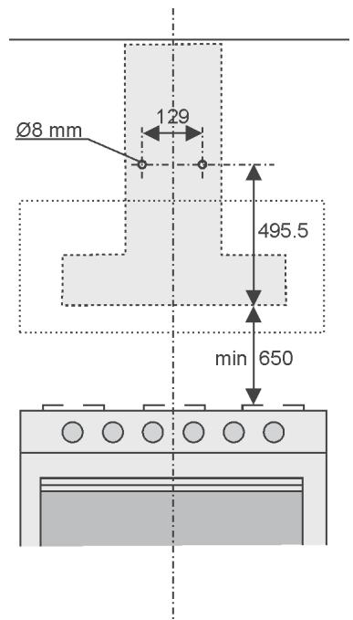
Fig. 4
Then hook the hood onto the bracket (Fig. 6). Adjust the horizontal position by moving the hood to the right or left according to the wall unit alignment. If the hood needs to be adjusted in height, operate on the adjusting screws (B) (provided). Once adjusted, without removing the hood, mark the other 4 holes to be drilled on the wall (C); unhook the hood and drill the holes marked (8 mm diameter); then use the 4 screw anchors and 4 screws provided for final fixing.
- Fit the electrical system plate, securing it with 2 screws (V) and 2 washers (Fig. 7).
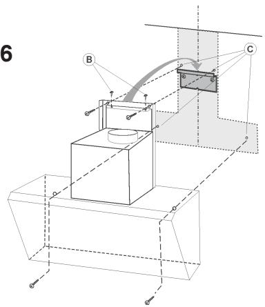
Fig. 6
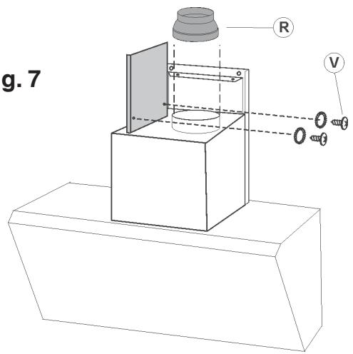
Fig. 7
INSTALLING THE FILTERING VERSION:
- Fitting the reducer: Position the reducer (R) above the air vent of the motor and exercise slight pressure (Fig.7).
7. Fitting the telescopic flues:
- Adjust the width of the telescopic flue support bracket (D) using the screws F indicated in Fig. 8.
- Then, using the screw anchors and the screws (G) provided, fit the bracket to the ceiling in such a way that it is in line with the hood (Fig. 8).
- Take the air baffle and fit the relative flange (W) with a rotary movement (Fig. 9); Fit a flexible hose to the flange (125 mm diameter) locking it with a metal clamp (hose and clamps not provided). Secure the air baffle to the upper flue (Fig. 9) with 4 screws.
- Fit the 2 glass stops to the sides of the lower flue: screw in the screw working from the inside of the lower flue an lock the glass stop (Fig. 10).
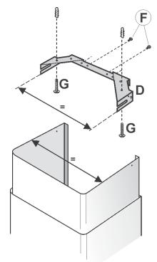
Fig. 8
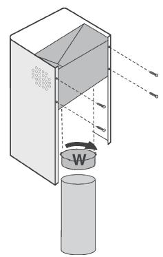
Fig. 9
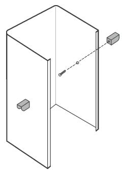
Fig. 10
- Connect the flexible hose to the reducer (R) on the air vent (Fig. 11).
- Make the electrical connection of the hood by means of the power cable.
- Fit the telescopic flues resting them on the hood; raise the upper flue as far as the ceiling and secure it with the 2 screws H (Fig.12).
- Secure the lower flue with 4 screws, working from the inside of the hood (Fig. 13).
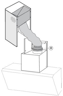
Fig. 11
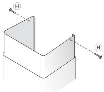
Fig. 12
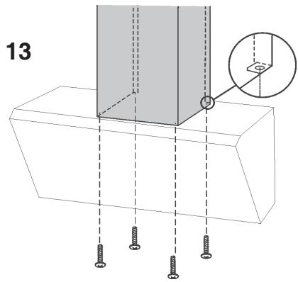
Fig. 13
- In the filtering version, a charcoal filter must be used. Check if it has been installed, and if not, install it by sliding the 2 filter clips into place and turn it inwards (Fig. 14).
- Fitting the grease drip trays: position the 2 drip trays inside the hood in proximity of the halogen lamps and move the trays sideways towards the outside of the hood (Fig. 15).
- Fitting the glass panel: Fit the 2 plastic strips on the upper edge of the glass panel (Fig. 16); Position the glass panel in the 2 glass stops and secure it to the hood with 2 screws and 4 washers (Fig. 16).
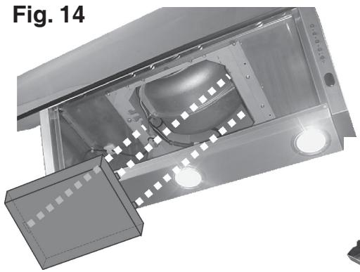
Fig. 14
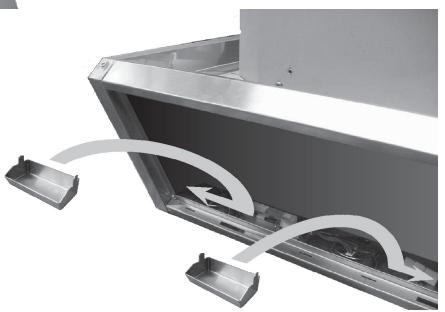
Fig. 15
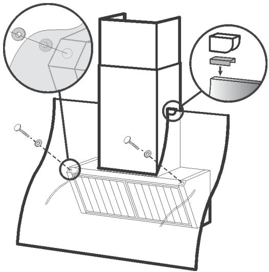
Fig. 16
INSTALLING THE DUCTING VERSION
6. Fitting the telescopic flues:
- Adjust the width of the telescopic flue support bracket (D) using the screws F indicated in Fig. 8.
- Then, using the screw anchors and the screws (G) provided, fit the bracket to the ceiling in such a way that it is in line with the hood (Fig. 8).
- Fit the 2 glass stops to the sides of the lower flue: screw in the screw working from the inside of the lower flue an lock the glass stop (Fig. 10).
- Connect the air exhaust pipe to the air vent using a metal clamp (pipe and clamps not provided).
- Make the electrical connection of the hood by means of the power cable.
- Fit the telescopic flues resting them on the hood; raise the upper flue as far as the ceiling and secure it with the 2 screws H (Fig.12).
- Secure the lower flue with 4 screws, working from the inside of the hood (Fig. 13).
- In the ducting version, the charcoal filter is not required; therefore if it has been installed, remove it by pushing the catch inwards and turning the filter downwards until the 2 clips slip out of their seats (Fig. 14).
- Fitting the grease drip trays: position the 2 drip trays inside the hood in proximity of the halogen lamps and move the trays sideways towards the outside of the hood (Fig. 15).
- Fitting the glass panel: Fit the 2 plastic strips on the upper edge of the glass panel (Fig. 16); Position the glass panel in the 2 glass stops and secure it to the hood with 2 screws and 4 washers (Fig. 16).
Technical data
- 1 Motor power 370 W
Voltage: 230-240V single phase - 3 halogen lamps 20W
- Supplied with 150~cm electricity supply cable with plug.
- Gross weight : Kg. 39.5
Net weight:Kg.34.5 - 2 metallic grease filters
Dimensions (Fig. 17)
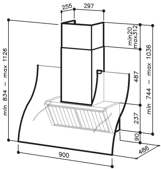
Fig. 17
FUNCTIONING OF THE APPARATUS
CONTROLS (Fig. 18):
A = Light switch.
B = Motor ON/OFF - 1 speed switch
C = II speed switch
D = III speed switch
E = IV speed switch
F = Infrared beam sensor
Pressing once again the active speed switch in that moment, the timer making the apparatus stop automatically starts working and the relative led starts to blink, this will last for 10' then the motor will stop together with the lights (if they are ON).
In this 10' time it is possible to change the motor speed. If you stop the motor you stop the counting.
At the end of 30 working hours, the light switch starts blinking to indicate that the anti-grease filter needs to be cleaned. To reset press the speed switch that was working.
Remote control working (Fig. 19):
G = Switch ON/OFF motor working at the same speed as when it had been turned OFF.
H = To increase speed
I = To lower speed
L = Light switch.
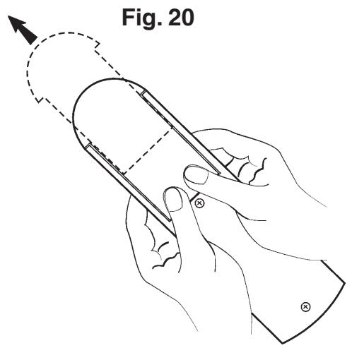
ATTENTION: the remote control needs a special care. Avoid it to come into contact with water and clean it periodically in order to avoid any grease deposit. The remote control must be fed by a 9V, "Transistor" type battery.
To get to the battery seat, pull the cover of the remote control (as indicated in Figure 20) making it slip towards the outside.
Get rid of the empty batteries safely, using the appropriate containers. In case you would have to eliminate the remote control, remember that you should first take the batteries off.

Fig. 18
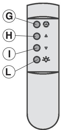
Fig. 19
ELECTRICITY CONNECTION
While connecting the electricity make sure that the tension is that indicated in the technical lable.
Before proceeding to cleaning or maintenance operations remove the tension.
Connecting the electricity must be performed by a specialised technician in conformity with the regulation in force.
This apparatus is constructed so as to belong to the I insulation class and therefore needs grounding.
MAINTENANCE
REMOVE THE TENSION AT THE HOOD (PLUG or SWITCH) BEFORE ANY OPERATION
Thorough servicing guarantees correct and long-lasting operation.
-Maintenance of the casing:
Avoid products containing abrasives when cleaning the casing.
--Maintenance of the grease filters:
The grease filters require regular maintenance and must be cleaned on average every two months depending on use.
About every 30 hours of operation the hood signals that the grease filters need to be cleaned by the light button flashing (Fig. 17A).
Remove the grease filters: grip the knob and push it towards the opposite side of the filter and turn the filter outwards (Fig. 21). Wash them with a normal neutral product available on the market and then thoroughly rinse and dry them. The filters can be washed in a dishwasher. Refit the grease filters. After cleaning the grease filters, reset the hour counter by pressing the current operating speed button.
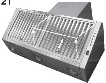
Fig. 21
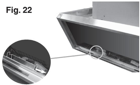
-Maintenance of the grease drip trays:
The grease drip trays require regular maintenance and must be emptied and cleaned on average every two months depending on use.
Removing the grease drip trays: Move the drip trays sideways towards the inside of the hood (Fig. 22) and remove them.
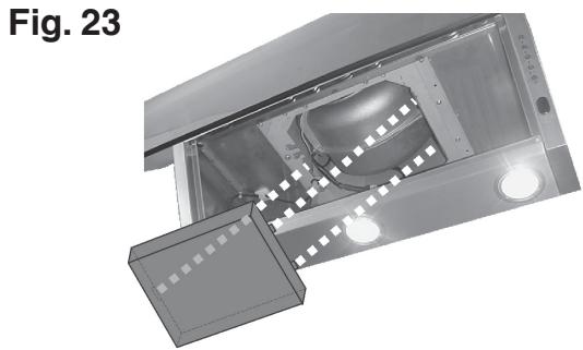
-Maintenance of the charcoal filter:
If using a hood in the filtering version, the charcoal filter needs to be replaced on average every six months depending on use.
Charcoal filter reference: AH4063-U1.
To remove the charcoal filter, first remove the grease filters (Fig.21). Then remove the charcoal filter by pushing the catch inwards and turning the filter downwards until the 2 clips slip out of their seats (Fig. 23). Replace the charcoal filter and refit the grease filters.
-Changing the halogen lamps:
To change the halogen bulbs open the cover levering from the proper slots (Fig.24). Change with a lamp of the same kind.
CAUTION: Do not handle glass bulb with bare hands.
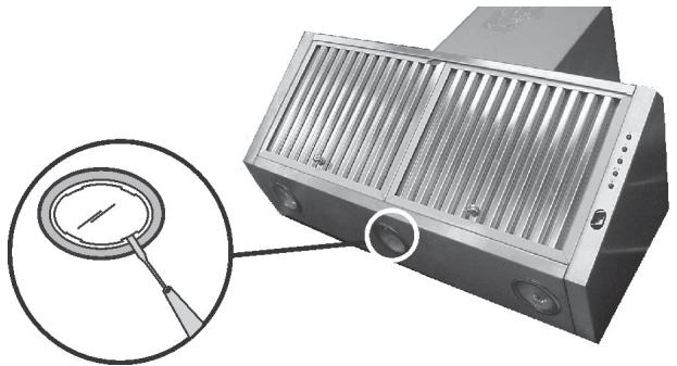
Fig. 24
IMPORTANTE: ANTES DE REALIZAR LA INSTALLACION O USAR SU CAMPANA, SIGA ESTAS INSTRUCCIONES:
BESCHRIJVING VAN HET APPARAAT
WERKING VAN HET APPARAAT
BEDIENINGEN (Afb. 18):