
DHT6605X - Range hood DE DIETRICH - Free user manual and instructions
Find the device manual for free DHT6605X DE DIETRICH in PDF.


| Product type | Cooker hood |
| Brand | De Dietrich |
| Model | DHT6605X |
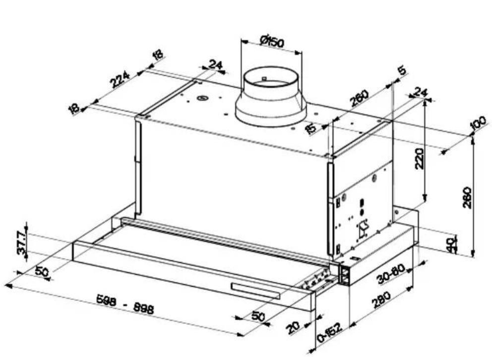
| Dimensions (W x D x H) | 598 x 500 x 450-850 mm (variable height with telescopic duct) |
| Net weight | 15 kg |
| Power supply | 220-240 V ~ 50 Hz |
| Motor power | 200 W |
| Lighting | 2 x LED (4 W each) |
| Control type | Electronic push buttons |
| Number of speeds | 4 speeds + intensive |
| Maximum extraction capacity | 650 m³/h |
| Maximum noise level | 65 dB(A) |
| Grease filter | Washable metal filter (aluminium) |
| Charcoal filter | Optional, for recirculation (model 120285) |
| Extraction mode | Extraction or recirculation (with charcoal kit) |
| Air outlet diameter | 150 mm |
| Energy class | A |
| Special functions | Timer, automatic shut-off, filter saturation indicator |
| Maintenance and cleaning | Wash the grease filter every month in the dishwasher; replace the charcoal filter every 3 to 6 months |
| Safety | Automatic shut-off in case of overheating, motor protection |
| Spare parts and repairability | Filters, LED lamps, controls available via De Dietrich after-sales service |
| General information | 2-year warranty; made in France |
Frequently Asked Questions - DHT6605X DE DIETRICH
User questions about DHT6605X DE DIETRICH
0 question about this device. Answer the ones you know or ask your own.
Ask a new question about this device
Download the instructions for your Range hood in PDF format for free! Find your manual DHT6605X - DE DIETRICH and take your electronic device back in hand. On this page are published all the documents necessary for the use of your device. DHT6605X by DE DIETRICH.
USER MANUAL DHT6605X DE DIETRICH
FR GUIDE D'UTILISATION
EN GUIDE TO INSTALLATION
natural_image
Modern kitchen interior with stainless steel appliances and large kitchen cabinets (no visible text or symbols)SOMMAIRE
FR
CONSIGNES DE SÉCURITÉ ....4
CARACTERISTIQUES 7
INSTALLATION 8
UTILISATION....10
ENTRETIEN 11
INDEX
EN
SAFETY INFORMATION 13
CHARACTERISTICS....16
INSTALLATION....17
USE....19
MAINTENANCE....20
ÍNDICE
ES
Composants
natural_image
3D architectural diagram of a room with green walls, a central circular component, and a wall-mounted platform (no text or symbols)MONTAGE AVEC FIXATION PAR ENCLIQUETAGE
natural_image
Diagram of a green rectangular component with arrows indicating direction, no text or symbols presentRaccordements
SORTIE DE L'AIR VERSION ASPIRANTE
natural_image
Hand inserting a green arrow on a device screen, enclosed in a circular frame (no text or symbols)Filtre anti-odeur (Version filtrante)
REPLACEMENT FILTRE AU CHARBON ACTIF
natural_image
Diagram of two mechanical components labeled A and B with green directional arrows indicating rotation or movement (no text or symbols beyond labels)Éclairage
Dear valued customer,
To discover a De Dietrich product is to experience the range of unique emotions which only high-value items can produce.
The attraction is immediate, from the moment you set eyes on the product. The sheer quality of the design shines through thanks to the timeless style and outstanding finishes which make each appliance an elegant and refined little masterpiece in its own right, each in perfect harmony with the others.
Next, comes the irresistible urge to touch it. De Dietrich's design makes extensive use of robust and prestigious materials. The accent is placed firmly upon authenticity.
By combining state-of-the-art technology with top quality materials, De Dietrich produces beautifully crafted products to help you get the most from the culinary arts, a passion shared by all lovers of cooking and fine food.
We hope that you enjoy using this new appliance and we would love to receive your suggestions and to answer any questions you may have. Please feel free to contact our customer service department via our website.
To benefit from the many advantages offered by the brand, we recommend that you register your product at: www.de-dietrich.com.
Thank you for choosing a De Dietrich product.
De Dietrich
You can find a full range of information about the brand at www.de-dietrich.com
Visit the De Dietrich Gallery, 6 rue de la Pépinière (Paris eighth district)
Open from Tuesday to Saturday from 10 am to 7 pm
Customer service department: 0892 02 88 04
For your safety and correct operation of the appliance, read this manual carefully before installation and use. Always keep these instructions with the appliance even if you move or sell it. Users must fully know the operation and safety features of the appliance.
The wire connection has to be done by specialized technician.
- The manufacturer will not be held liable for any damages resulting from incorrect or improper installation.
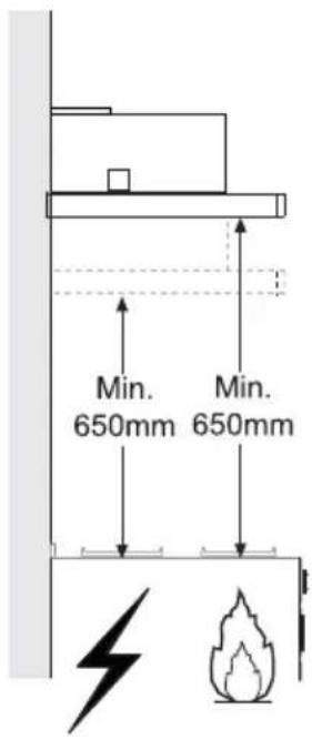
- The minimum safety distance between the cooker top and the extractor hood is 650 mm (some models can be installed at a lower height, please refer to the paragraphs on working dimensions and installation).
- If the instructions for installation of the gas hob specify a greater distance, this must be respected.
- Check that the mains voltage corresponds to that indicated on the rating plate fixed to the inside of the hood.
- Means for disconnection must be incorporated in the fixed wiring in accordance with the wiring rules.
- For Class I appliances, check that the domestic power supply guarantees adequate earthing.
- Connect the extractor to the exhaust flue through a pipe of minimum diameter 120 mm. The route of the flue must be as short as possible.
- Regulations concerning the discharge of air have to be fulfilled.
-
Do not connect the extractor hood to exhaust ducts carrying combustion fumes (boilers, fireplaces, etc.).
-
If the extractor is used in conjunction with non-electrical appliances (e.g. gas burning appliances), a sufficient degree of aeration must be guaranteed in the room in order to prevent the backflow of exhaust gas. When the cooker hood is used in conjunction with appliances supplied with energy other than electric, the negative pressure in the room must not exceed 0,04 mbar to prevent fumes being drawn back into the room by the cooker hood.
- The air must not be discharged into a flue that is used for exhausting fumes from appliances burning gas or other fuels.
- If the supply cord is damaged, it must be replaced from the manufacturer or its service agent.
- Connect the plug to a socket complying with current regulations, located in an accessible place.
- With regards to the technical and safety measures to be adopted for fume discharging it is important to closely follow the regulations provided by the local authorities.
⚠️WARNENH:cBefore installing the Hood, remove the protective films.
- Use only screws and small parts supplied with the hood.
⚠️ WARNENH: Failure to install the screws or fixing device in accordance with these instructions may result in electrical hazards.
- Do not look directly at the light through optical devices (binoculars, magnifying glasses...).
- Do not flambè under the range hood; risk of fire.
- This appliance can be used by children aged from 8 years and above and persons with reduced physical, sensory or mental capabilities or lack of experience and knowledge if they have been given supervision or instruction concerning use of the appliance in a safe way and understand the hazards involved. Children shall not play with the appliance. Cleaning and user maintenance shall not be made by children without supervision.
- Children should be supervised to ensure that they do not play with the appliance.
- The appliance is not to be used by persons (including children) with reduced physical, sensory or mental capabilities, or lack of experience and knowledge, unless they have been given supervision or instruction.
⚠️ Accessible parts may become hot when used with cooking appliances. - Clean and/or replace the Filters after the specified time period (Fire hazard). See paragraph Care and Cleaning.
- There shall be adequate ventilation of the room when the range hood is used at the same time as appliances burning gas or other fuels (not applicable to appliances that only discharge the air back into the room).
- The symbol 📁 on the product or on its packaging indicates that this product may not be treated as household waste. Instead it shall be handed over to the applicable collection point for the recycling of electrical and electronic equipment. By ensuring this product is disposed of correctly, you will help prevent potential negative consequences for the environment and human health, which could otherwise be caused by inappropriate waste handling of this product. For more detailed information about recycling of this product, please contact your local city office, your household waste disposal service or the shop where you purchased the product.
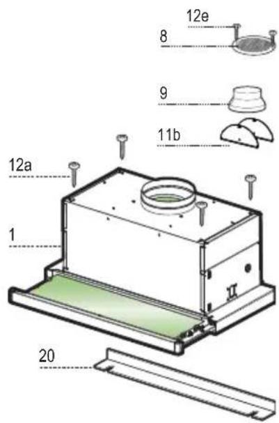
Components
| Ref. | Q.ty | Product | Components |
| 1 | 1 | Hood Body, complete with: Controls, Light, Blower, Filters | |
| 8 | 1 | Directional Air Outlet grille | |
| 9 | 1 | Reducer Flange ø 150-120 mm | |
| 20 | 1 | Closing | element |
| 11b | 2 | Flap c | |
Ref. Q.ty Installation Components
| 12a | 4 | Screws 4,2 x 44,4 |
| 12e | 2 | Screws 2,9 x 9,5 |
| Q.ty | Documentation | |
| 1 | Instruction | Manual |
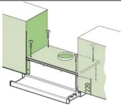
Drilling the Support surface and Fitting the Hood SCREW FITTING
- The hood support surface must be 220 mm above the bottom surface of the wall units.
- Drill the support with a 4,5 mm drill bit, using the drilling template provided.
- Cut a hole 150 mm in size on the support surface, using the drilling template provided.
• Fix using the 4 screws 12a (4,2 x 44,4) provided.
natural_image
3D architectural diagram of a room with green walls, a central circular component, and a 220mm scale indicator (no text or symbols)SNAP-ON FITTING
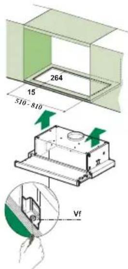
- The hood can be installed either directly on the bottom surface of the wall units using snap-on side supports.
- Cut a fitted opening in the bottom surface of the wall unit, as shown.
- Insert the hood until the side supports snap into place.
- Lock in position by tightening the screws Vf from underneath the hood.
CLOSING ELEMENT
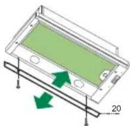
- The space between the edge of the hood and the rear wall can be closed by applying the element 20 provided, using the screws supplied for this purpose.
natural_image
Diagram of a green panel with arrows indicating direction, no text or symbols presentCZŃNecąiŻŃsc
AERcOUTLETcDUCTENHcVERSEONc
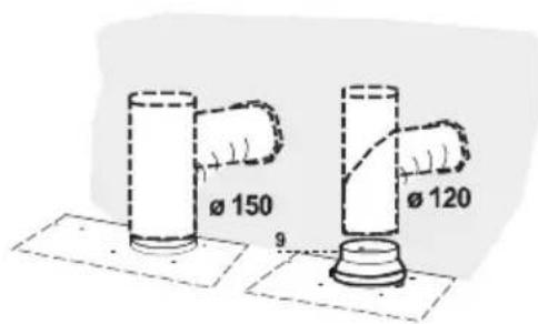
When installing the Ducting version, join the Hood to the outlet duct using a rigid or flexible pipe 150 or 120 mm, selection of which is at the discretion of the installation technician.
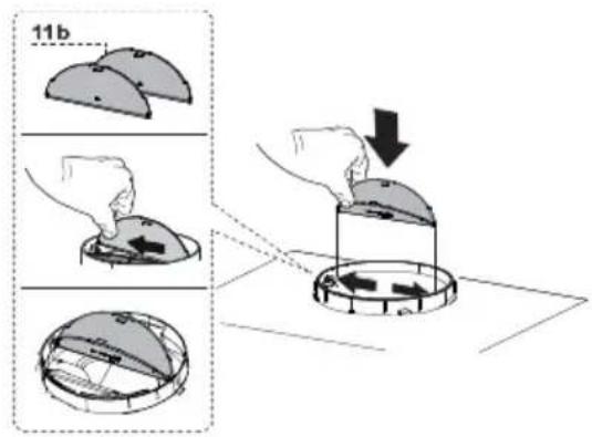
- Insert flaps 11b on the Hood Canopy Outlet.
Connecting the ø 150 pipe
- Fasten the pipe using suitable pipe clamps. The materials required to do so are not provided.
Connecting the ø 120 pipe
- To connect using a 120 mm pipe, insert the reduction Flange 9 onto the Hood Canopy Outlet.
- Fasten the pipe using suitable pipe clamps. The materials required to do so are not provided.
- In both cases, any Activated Charcoal Filters must be removed.
RECIRCULATION VERSION AIR OUTLET
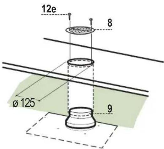
- Cut a hole 125 mm in any shelf that may be positioned over the hood.
- Insert the reducer flange 9 on the hood body outlet.
- Connect the flange to the outlet on the shelf over the hood by using a flexible or rigid pipe 120mm .
- Fix the pipe in position using sufficient pipe clamps (not supplied).
- Fix the air outlet grid 8 on the recirculation air outlet by using the 2 screws 12e (2,9 x 9,5) provided.
- Ensure that the activated charcoal filters have been inserted.
ELECTRICAL CONNECTION
- Connect the hood to the mains through a two-pole switch having a contact gap of at least 3 mm.
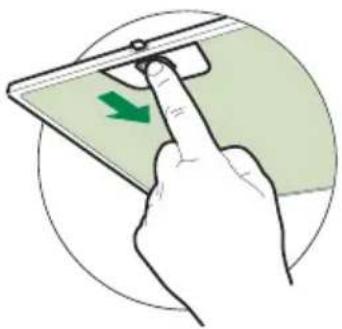
- When opening the sliding carriage for the first time after installing the hood, pull it out briskly until it clicks.
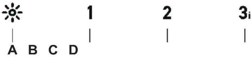
| ButtonFunction | |
| A | Turns the lighting system on and off at maximum intensity, by a brief pressure. Lights can be switch on and off at every speed. |
| DelaySuitable to complete elimination of residual odours. Long pressure: activates the automatic switch - off with a 5 minutes delay. It can be activated at every speed.It can be desabled pressing the speed button, turning the motor off. | |
| BBrief | pressure. Turns the suction motor on and off at speed one. |
| CBrief | pressure. Turns the suction motor on and off at speed two. |
| D | Turns the suction motor on at speed three. |
| - Press and hold 3 seconds on third speed button switches to intensive speed with a duration of 6 minutes. Led flashes.- Press and hold 3 seconds before the 6 minutes end switches back to third speed. Led is on.- Short push before the 6 minutes elapse switches the hood off. | |
Grease filters
CLEANING METAL CASSETTE GREASE FILTERS
- The filters must be cleaned every 2 months, or more frequently in case of particularly heavy use of the hood. Filters can be washed in a dishwasher.
- Pull out the sliding suction panel.
- Remove the filters one by one, after having disconnected the relative fastening elements.
- Wash the filters, taking care not to bend them. Let them get dry before refitting them. (The colour of the filter surface may change throughout the time but this has no influence to the filter efficiency).
- When refitting the filters, make sure that the handle is visible on the outside.
- Close the sliding suction panel.
natural_image
Hand inserting a green arrow on a device screen, enclosed in a circular frame (no text or symbols)Activated charcoal filter (Recirculation version)
These filters are not washable and cannot be regenerated, and must be replaced approximately every 4 months of operation, or more frequently with heavy usage.
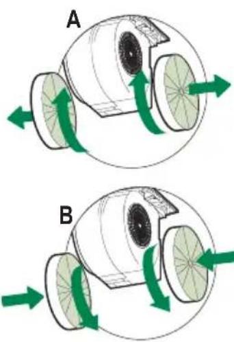
REPLACING THE ACTIVATED CHARCOAL FILTER
- Remove the metal grease filters
- Remove the saturated activated charcoal filter as shown (A).
- Fit the new filters (B).
- Replace the metal grease filters.
natural_image
Diagram of two mechanical components labeled A and B with green directional arrows indicating motion or force (no text or symbols beyond labels)Lighting unit
- For replacement contact technical support ("To purchase contact technical support").
"LED S1000 type lamp of 100W are not replaceable by the user".
Componentes
natural_image
3D architectural diagram of a room with green walls, a central circular component, and a 220mm dimension label (no text or symbols beyond measurement markers)natural_image
3D diagram of a green rectangular component with arrows indicating direction, no text or symbols presentYoneKioneΦ
ŚNLЛКН КА NLRA AN VARŚLÓN NŚPЛRNNTA
natural_image
Hand inserting a green arrow on a device screen, enclosed in a circular frame (no text or symbols)natural_image
Diagram of two mechanical components labeled A and B with green directional arrows indicating rotation or movement (no text or symbols beyond labels)Iluminación
Componentes
natural_image
3D architectural diagram of a room with green walls, a central circular component, and a wall-mounted platform (no text or symbols)natural_image
Diagram of a device with green internal structure and directional arrows, no text or symbols presentLigaθχeΦ
ŚNÍKN KA NR KN VARSÃO NŚPJRNNTA
natural_image
Hand inserting a green arrow on a device screen, enclosed in a circular frame (no text or symbols)natural_image
Diagram of two mechanical components labeled A and B with green directional arrows indicating rotation or movement (no text or symbols beyond labels)Iluminação
Komponenten
natural_image
3D architectural diagram of a room with green walls, a central circular component, and a wall-mounted platform (no text or symbols)natural_image
Diagram of a green rectangular component with arrows indicating direction, mounted on a metal frame (no text or symbols)AÑschlÉssec
LUŠTAUSTRETTcENcDERcABZUHSiVERSEONc
natural_image
Hand inserting a green arrow on a device screen, enclosed in a circular frame (no text or symbols)natural_image
Diagram of two mechanical components labeled A and B with green directional arrows indicating motion or force (no text or symbols beyond labels)Beleuchtung
LED-Strahler
- SOMMAIRE
- INDEX
- ÍNDICE
- MONTAGE AVEC FIXATION PAR ENCLIQUETAGE
- Raccordements
- SORTIE DE L'AIR VERSION ASPIRANTE
- Filtre anti-odeur (Version filtrante)
- REPLACEMENT FILTRE AU CHARBON ACTIF
- Éclairage
- Drilling the Support surface and Fitting the Hood SCREW FITTING
- SNAP-ON FITTING
- CLOSING ELEMENT
- CZŃNecąiŻŃsc
- AERcOUTLETcDUCTENHcVERSEONc
- Connecting the ø 150 pipe
- Connecting the ø 120 pipe
- RECIRCULATION VERSION AIR OUTLET
- ELECTRICAL CONNECTION
- Grease filters
- CLEANING METAL CASSETTE GREASE FILTERS
- Activated charcoal filter (Recirculation version)
- REPLACING THE ACTIVATED CHARCOAL FILTER
- Lighting unit
- Componentes
- YoneKioneΦ
- ŚNLЛКН КА NLRA AN VARŚLÓN NŚPЛRNNTA
- Iluminación
- LigaθχeΦ
- ŚNÍKN KA NR KN VARSÃO NŚPJRNNTA
- Iluminação
- AÑschlÉssec
- LUŠTAUSTRETTcENcDERcABZUHSiVERSEONc
- Beleuchtung
- LED-Strahler
Brand : DE DIETRICH
Model : DHT6605X
Category : Range hood