DF 7290 - Dishwasher AEG-ELECTROLUX - Free user manual and instructions
Find the device manual for free DF 7290 AEG-ELECTROLUX in PDF.
| Product type | Built-in extractor hood |
| Brand | AEG-ELECTROLUX |
| Model | DF 7290 |
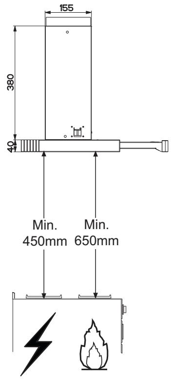
| Minimum height above cooking surface | 650 mm |
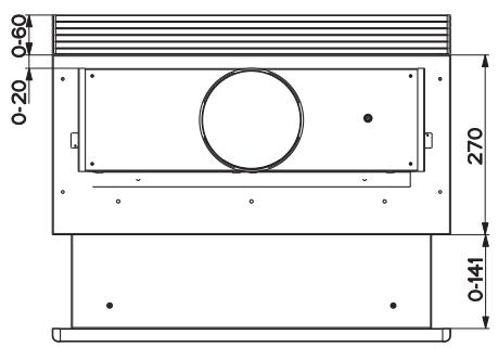
| Air outlet diameter | 120 or 150 mm |
| Lighting power | Fluorescent lamp 11 W |
| Number of motor speeds | 4 (1, 2, 3, turbo) |
| Control type | Drawer opening for automatic activation |
| Grease filters | Self-supporting metal, dishwasher-safe |
| Activated charcoal filter | Not washable, replace every 3-4 months |
| Evacuation type | Recirculation or external evacuation |
| Power supply | 220-240 V, with bipolar switch |
| Protection class | Grounding required |
| Material | Stainless steel or painted |
| Installation | Built-in under wall cabinet |
| Included accessories | Flanges Ø120 and Ø150, connection ring, closure profile, directional grille |
| Surface maintenance | Damp cloth and neutral detergent |
| Warranty | See manual for conditions |
| Recycling | Do not dispose with household waste, take to collection point |
Frequently Asked Questions - DF 7290 AEG-ELECTROLUX
User questions about DF 7290 AEG-ELECTROLUX
0 question about this device. Answer the ones you know or ask your own.
Ask a new question about this device
Download the instructions for your Dishwasher in PDF format for free! Find your manual DF 7290 - AEG-ELECTROLUX and take your electronic device back in hand. On this page are published all the documents necessary for the use of your device. DF 7290 by AEG-ELECTROLUX.
USER MANUAL DF 7290 AEG-ELECTROLUX
RECOMMENDATIONS AND SUGGESTIONS
The Instructions for Use apply to several versions of this appliance. Accordingly, you may find descriptions of individual features that do not apply to your specific appliance.
INSTALLATION
- The manufacturer will not be held liable for any damages resulting from incor-rect or improper installation.
- The minimum safety distance between the cooker top and the extractor hood is 650 mm (some models can be installed at a lower height, please refer to the paragraphs on working dimensions and installation).
- Check that the mains voltage corresponds to that indicated on the rating plate fixed to the inside of the hood.
- For Class I appliances, check that the domestic power supply guarantees adequate earthing.
Connect the extractor to the exhaust flue through a pipe of minimum diameter 120 mm. The route of the flue must be as short as possible.
- Do not connect the extractor hood to exhaust ducts carrying combustion fumes (boilers, fireplaces, etc.).
- If the extractor is used in conjunction with non-electrical appliances (e.g. gas burning appliances), a sufficient degree of aeration must be guaranteed in the room in order to prevent the backflow of exhaust gas. The kitchen must have an opening communicating directly with the open air in order to guarantee the entry of clean air.
USE
- The extractor hood has been designed exclusively for domestic use to eliminate kitchen smells.
- Never use the hood for purposes other than for which it has been designed.
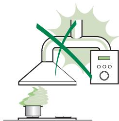
- Never leave high naked flames under the hood when it is in operation.
- Adjust the flame intensity to direct it onto the bottom of the pan only, making sure that it does not engulf the sides.
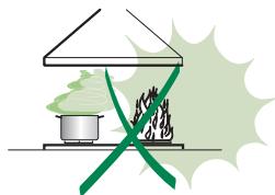
- Deep fat fryers must be continuously monitored during use: overheated oil can burst into flames.
- Do not flambe under the range hood; risk of fire
- This appliance is not intended for use by persons (including children) with re-duced physical, sensory or mental capabilities, or lack of experience and knowledge, unless they have been given supervision or instruction concerning use of the appliance by a person responsible for their safety.
- Children should be supervised to ensure that they do not play with the appliance.
MAINTENANCE
- Switch off or unplug the appliance from the mains supply before carrying out any maintenance work.
- Clean and/or replace the Filters after the specified time period (Fire hazard)
- Clean the hood using a damp cloth and a neutral liquid detergent.
The symbol on the product or on its packaging indicates that this product may not be treated as household waste. Instead it shall be handed over to the applicable collection point for the recycling of electrical and electronic equipment. By ensuring this product is disposed of correctly, you will help prevent potential negative consequences for the environment and human health, which could otherwise be caused by inappropriate waste handling of this product. For more detailed information about recycling of this product, please contact your local city office, your household waste disposal service or the shop where you purchased the product.
CHARACTERISTICS
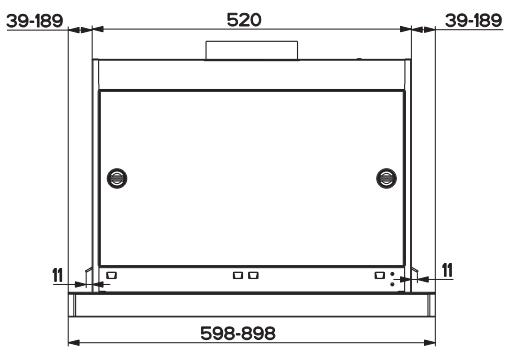
Dimensions
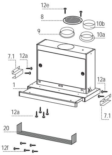
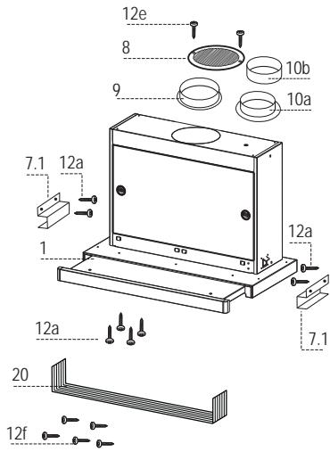
Components
Ref. Q.ty Product Components
| 1 | 1 | Hood Body, complete with: Controls, Light, Blower, Filters |
| 8 | 1 | Directional Air Outlet grille |
| 9 | 1 | Flange ø 150 mm |
| 10a | 1 | Flange ø 120 mm |
| 10b | 1 | Adapting ring ø 120-125 mm |
| 20 | 1 | Closing element |
| Ref. Q.ty | Installation Components | |
| 7.1 | 2 | Hood Body Fixing Brackets |
| 12a | 8 | Screws 3,5 x 16 |
| 12e | 2 | Screws 2,9 x 12,7 |
| 12f | 5 | Screws 2,9 x 9,5 |
| Q.ty | Documentation | |
| 1 | Instruction Manual | |
INSTALLATION
Drilling the Support surface and Fitting the Hood
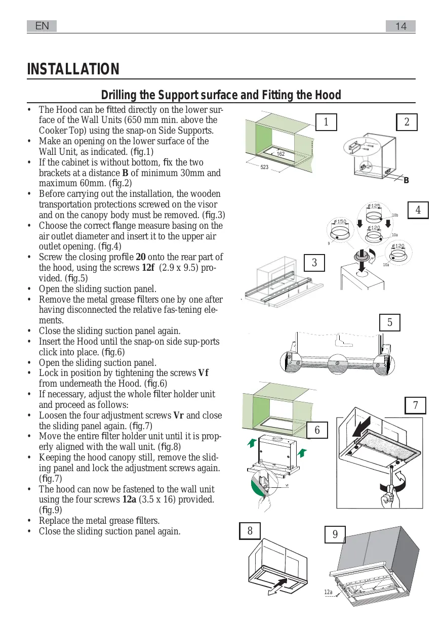
- The Hood can be fitted directly on the lower surface of the Wall Units (650 mm min. above the Cooker Top) using the snap-on Side Supports.
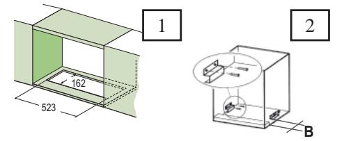
- Make an opening on the lower surface of the Wall Unit, as indicated. (fig.1)
- If the cabinet is without bottom, fix the two brackets at a distance B of minimum 30mm and maximum 60mm . (fig.2)
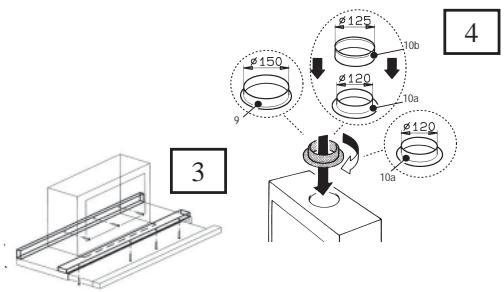
Before carrying out the installation, the wooden transportation protections screwed on the visor and on the canopy body must be removed. (fig.3) - Choose the correct flange measure basing on the air outlet diameter and insert it to the upper air outlet opening. (fig.4)
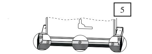
- Screw the closing profile 20 onto the rear part of the hood, using the screws 12f (2.9 x 9.5) provided. (fig.5)
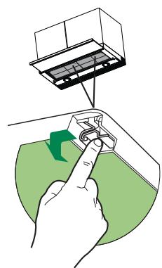
- Open the sliding suction panel.
- Remove the metal grease filters one by one after having disconnected the relative fas-tening elements.
- Close the sliding suction panel again.
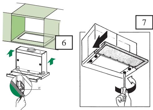
- Insert the Hood until the snap-on side sup-ports click into place. (fig.6)
- Open the sliding suction panel.
- Lock in position by tightening the screws Vf from underneath the Hood. (fig.6)
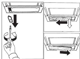
- If necessary, adjust the whole filter holder unit and proceed as follows:
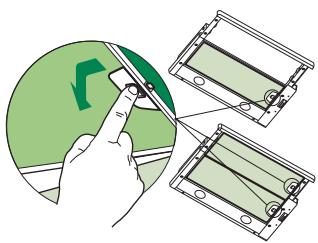
- Loosen the four adjustment screws Vr and close the sliding panel again. (fig.7)
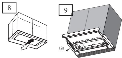
- Move the entire filter holder unit until it is properly aligned with the wall unit. (fig.8)
- Keeping the hood canopy still, remove the sliding panel and lock the adjustment screws again. (fig.7)
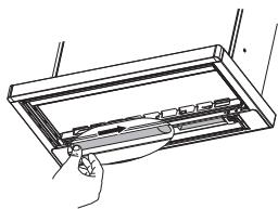
- The hood can now be fastened to the wall unit using the four screws 12a (3.5 x 16) provided. (fig.9)
- Replace the metal grease filters.
- Close the sliding suction panel again.
CONNECTIONS
DUCTED VERSION AIR EXHAUST SYSTEM
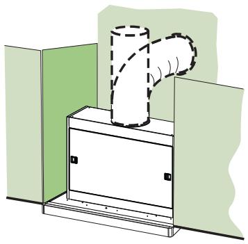
When installing the hood in ducting version, a rigid or a flexible pipe with the diameter corresponding to the flange diameter is used in order to connect the hood to the air outlet piping.
Fix the pipe with an adequate quantity of pipe clamps (not supplied).
- Remove possible charcoal filters.
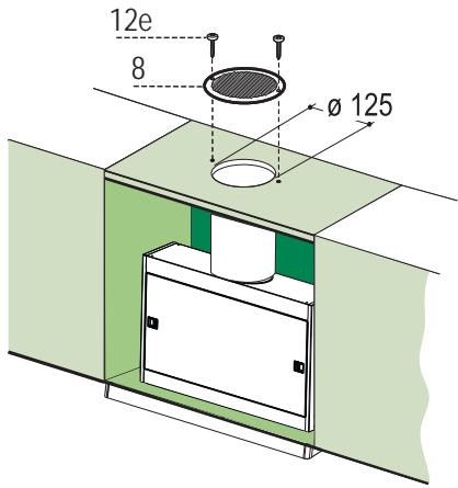
RECIRCULATION VERSION AIR OUTLET
- Cut a hole 125mm in any shelf that may be positioned over the hood.
- Insert the flange 10a on the hood body outlet.
- Connect the flange to the outlet on the shelf over the hood using a flexible or rigid pipe 120mm .
Fix the pipe in position using sufficient pipe clamps (not supplied).
Fix the directional grille 8 on the recirculation air outlet using the 2 screws 12e (2,9 x 12,7) provided. - Ensure that the activated charcoal filters have been inserted.
ELECTRICAL CONNECTION
- Connect the hood to the mains through a two-pole switch having a contact gap of at least 3 mm.
USO
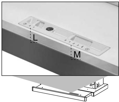
By pulling out the sliding panel it is possible to automatically activate all the hood functions. By simply closing the sliding panel all the functions are switched off.
| SWITCH | FUNCTIONS | ||
| L | Light | Switches the lighting system on and off | |
| M | Motor | Switches the extractor motor on and off | |
| 1. | Low speed, used for a continuous and silent air change in the presence of light cooking vapour. | ||
| 2. | Medium speed, suitable for most operating conditions, thanks to an optimum relation between hood performance and noise. | ||
| 3. | Maximum speed, suitable when the highest cooking vapour emission has to be eliminated for longer periods. | ||
| i. | Intensive speed, suitable for the strongest cooking vapours and odours. | ||
GREASE FILTERS
CLEANING METAL CASSETTE GREASE FILTERS
- The filters must be cleaned every 2 months, or more frequently in case of particularly heavy use of the hood. Filters can be washed in a dishwasher.
Pull out the sliding suction panel. - Remove the filters one by one, after having disconnected the relative fastening elements.
- Wash the filters, taking care not to bend them. Let them get dry before refitting them. (The colour of the filter surface may change throughout the time but this has no influence to the filter efficiency).
- When refitting the filters, make sure that the handle is visible on the outside.
- Close the sliding suction panel.
CHARCOAL FILTER (RECYCLING VERSION))
REPLACING CHARCOAL FILTERS
- These filters are not washable and cannot be regenerated, and must be replaced approximately every four months or more frequently by particularly heavy use.
Pull out the sliding suction panel. - Remove the grease filters.
- Remove the saturated carbon filter by releasing the fixing hooks
- Fit the new filter by hooking it into its seating.
- Replace the grease filters.
- Close the sliding suction panel.
LIGHTING
LIGHT REPLACEMENT
11 W fluorescent light
- Remove the metal terminals fixing the glass.
- Slide the glass cover out of one of the fastening clips. Lower the unfastened part of the glass cover slightly, so that the cover can be completely removed.
- Replace the light with a new one of the same type and rating.
- Replace the glass cover in reverse order.
INHOUDSOPGAVE
ADVIEZEN EN SUGGESTIES 19
EIGENSCHAPPEN 21
INSTALLATIE 23
GEBRUK 24
ONDERHOUD 25
ADVIEZEN EN SUGGESTIES
Ref. Installatieonderdelen
| 7.1 | 2 | Bevestigingsbeugels wasemkap |
| 12a | 8 | Schroeven 3,5 x 16 |
| 12e | 2 | Schroeven 2,9 x 12,7 |
| 12f | 5 | Schroeven 2,9 x 9,5 |
Documentationie
| 1 | Gebruksaanwijzing |