412-005 - Ventilateur domestique Anslut - Free user manual and instructions
Find the device manual for free 412-005 Anslut in PDF.

User questions about 412-005 Anslut
0 question about this device. Answer the ones you know or ask your own.
Ask a new question about this device
Download the instructions for your Ventilateur domestique in PDF format for free! Find your manual 412-005 - Anslut and take your electronic device back in hand. On this page are published all the documents necessary for the use of your device. 412-005 by Anslut.
USER MANUAL 412-005 Anslut
natural_image
White desktop fan with mesh grille and stand, no visible text or symbolsSE Bruksanvisning för bordsfläkt
NO Bruksanvisning for bordvifte
PL Instrukcja obsługi wentylatora biurkowego
EN User Instructions for Table Fan
SE - Bruksanvisning i original
EN - Operating instructions (Translation of the original instructions)
Jula reserves the right to make changes. In the event of problems, please contact our service department.
www.jula.com
Tillverkare/ Produsent / Produenci/ Manufacturer
Jula AB, Box 363, 532 24 SKARA
Importör/ Importør/ Importer/ Importer
Care for the environment!
Must not be discarded with household waste! This product contains electrical or electronic components that should be recycled. Leave the product for recycling at the designated station e.g. the local authority's recycling station.
SVENSKA....6
SÄKERHETSANVISNINGAR....6
TEKNISKA DATA....7
BESKRIVNING 8
DELAR....8
MONTERING 9
MONTERING AV FLÄKTROTOR OCH GALLER....9
MONTERING AV FOT 9
ANVÄNDNING....10
START/STOPP OCH VARVTALSINSTÄLLNING....10
VINKELINSTÄLLNING 10
RENGÖRING 10
NORSK 11
SIKKERHETSANVISNINGER 11
TEKNISKE DATA 12
BESKRIVELSE....13
DELER 13
MONTERING AV FOT 14
MONTERING....14
MONTERING AV VIFTEROTOR OG GITTER 14
BRUK....15
START/STOPP OG TURTALLSINNSTILLING....15
VINKELINNSTILLING....15
RENGJ∅RING....15
POLSKI 16
ZASADY BEZPIECZEŃSTWA 16
DANE TECHNICZNE 17
OPIS 18
CZEŚCI....18
MONTAŻ 18
MONTAŻ PODSTAWY....18
MONTAŻ WIRNIKA I KRATKI 19
SPOSÓB UŻYCIA 19
SAFETY INSTRUCTIONS....21
TECHNICAL DATA....22
DESCRIPTION 23
PARTS 23
ASSEMBLY....23
ASSEMBLY OF THE BASE 23
ASSEMBLY OF THE FAN BLADE AND GRILLE 24
USE....24
START/STOP AND SPEED SETTING....25
ANGLE SETTING....25
CLEANING 25
natural_image
Diagram of a fan-shaped electric fan with internal blades and base, showing airflow direction (no text or symbols)MONTERING AV FOT
natural_image
Technical line drawing of a mechanical component with no visible text or symbolsFig. 2
natural_image
Diagram of a curved, segmented structure with internal grid lines and a small object on top (no text or symbols)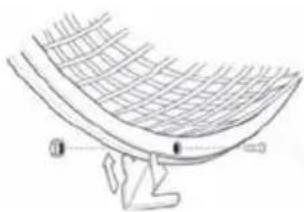
natural_image
Line drawing of a curved structure with grid pattern and two labeled points (no text or symbols)natural_image
Diagram of a fan-shaped electric fan with cooling effect, showing blade and base components (no text or labels)MONTERING AV FOT
natural_image
Diagram of a curved fan or girdle with radial lines and a hand holding the top edge (no text or symbols)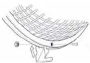
natural_image
Line drawing of a curved structure with grid pattern and two small human figures at the base (no text or symbols)natural_image
Diagram of a fan-shaped electric fan mounted on a base with a circular base, showing airflow direction (no text or symbols)MONTAŻ PODSTAWY
natural_image
Technical illustration of a mechanical component with no visible text or symbolsRys. 2
Nałóż wirnik na wał
natural_image
Diagram of a curved, segmented structure with diagonal lines and a small protrusion (no text or symbols)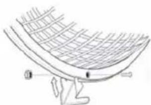
natural_image
Line drawing of a curved structural component with grid pattern and base (no text or symbols)Read the Operating Instructions carefully before use!
Save these instructions for future reference.
Always follow these basic safety instructions when using electrical appliances.
WARNING! Follow the instructions below to reduce the risk of burns, fire, electric shock or personal injury.
- Check that the mains voltage corresponds to the rated voltage on the type plate.
- Do not use the appliance with a speed controller – risk of electric shock.
- The appliance is not intended to be used by persons (children or adults) with any form of functional disorders, or by persons who do not have sufficient experience or knowledge on how to use it, unless they have received instructions concerning the use of the appliance from someone who is responsible for their safety. Keep children under supervision to make sure they do not play with the appliance. Do not allow children to use, clean or maintain the appliance without supervision.
• Never leave the appliance unattended when switched on. - Do not use the appliance if it is damaged or not working properly, or if the power cord or plug are damaged. Take the appliance to an authorised service centre to be checked, repaired or adjusted.
- Do not attempt to repair the appliance yourself. Return it to an authorised electrician or service centre.
- Do not expose the appliance, the power cord or the plug to water or any other liquid – risk of electric shock.
- Do not use the appliance close to baths, showers, wash basin or swimming pools.
- Do not install the appliance near sources of heat, e.g. radiators, cookers or other equipment that produces heat.
- Do not expose the appliance to high temperatures or direct sunlight.
- Do not subject the appliance to impact or continuous vibration.
• Do not expose the machine to a dusty environment. - Do not place the appliance so that it does not receive sufficient ventilation (for example, in a cupboard or on a shelf).
- Do not place the appliance on an uneven surface.
- Switch off the appliance and unplug the power cord when the appliance is not in use, and before assembling/dismantling parts or cleaning. Do not start the machine until it is fully assembled.
-
Avoid contact with moving parts. Never insert any objects or body parts in the equipment's openings.
-
Do not cover the appliance or place it near curtains or furniture – fire risk.
• The appliance is only intended for household use. - Switch off the appliance, unplug the power cord, and wait until all moving parts have completely stopped before moving the appliance.
- Do not use accessories other than those recommended or sold by the appliance manufacturer. The use of other accessories can result in fire, electric shock or personal injury.
• Make sure the appliance is stable before starting it.
• Do not immerse the machine in water or any other liquid. - A damaged power cord must be replaced by an authorised service centre, or qualified person, to ensure safe use.
Read these instructions carefully before use, and save them for future reference.
TECHNICAL DATA
| Air flow 27 m3/min |
| Power in standby mode 0 W |
| Weight 1,9 kg |
| Noise level 52 dB |
| Operating value standard IEC 60879:1986 (corr. 1992) |
| Nominal output 31,2 W |
| Cable length 1,3 m |
| Operating value 0,9 (m3/min)/W |
| Air velocity 2,2 m/s |
| Voltage 230 V |
| Dimensions H52x∅30 cm |
| Power 40 W |
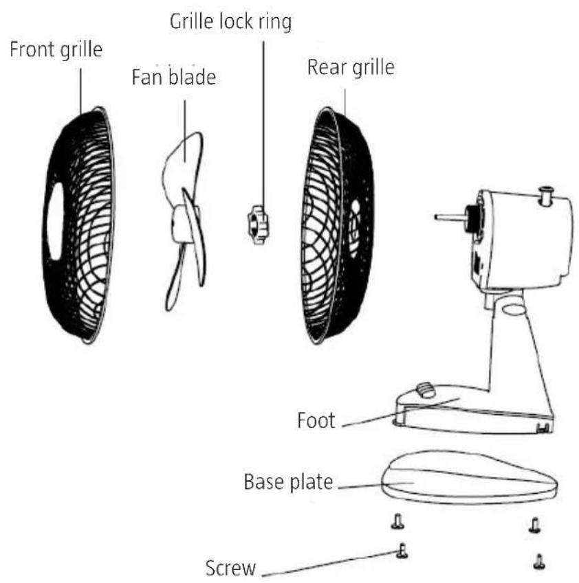
DESCRIPTION
PARTS
ASSEMBLY
natural_image
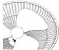
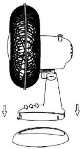
Diagram of a fan-shaped device with internal blades and base, showing airflow direction (no text or symbols)ASSEMBLY OF THE BASE
- Place the base on a flat surface.
- Lower the appliance's shaft into the base and secure with screws. Fit the fan blade on the motor shaft.
- There is a bag with 2 screws in the base plate. Remove the bag of screws and snap the base plate onto the brackets on the base. Check that the base plate locks into position and insert and tighten the 2 fastening screws in the holes in the base plate. Do not overtighten. Do not use the fan without the base plate mounted.
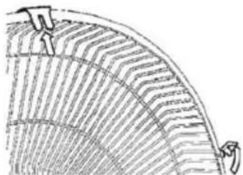
ASSEMBLY OF THE FAN BLADE AND GRILLE
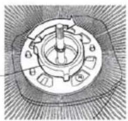
Fig. 1
Lock nut
natural_image
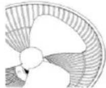
Technical diagram of a mechanical component with no visible text or symbolsFig. 2
Fit the fan blade on the shaft
- Remove the lock nut from the motor shaft by turning it anti-clockwise.
- Place the rear grille against the front of the motor housing, with the handle facing upwards. The guide pins on the motor housing should mate in the holes in the rear grille (fig. 1).
- Lock the grille in place, by refitting the lock nut and tighten by hand (fig. 1). Do not overtighten.
- Fit the fan blade on the motor shaft with the slot at the rear of the blade over the pin in the motor shaft.
Fig. 3 Fig. 4
natural_image
Diagram of a curved, segmented structure with diagonal lines and two small protrusions (no text or symbols)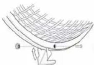
natural_image
Line drawing of a curved structural component with grid pattern and base (no text or symbols)• Fold out the locking clips on the front grille (fig. 3).
- Place the front grille against the rear grille, so that the holes along the edges are aligned. Press the grille clips in position over the edge of the grille. Insert the screw through the hole and screw on the nut (fig. 4).
USE
IMPORTANT!
- Put the appliance in a suitable place as set out in the safety instructions.
- Route the power cord so that there is no risk of tripping over it.
• Do not mount the appliance on a wall or ceiling. - Remove the cable tie and unwrap the cord before use.
Fig. 5
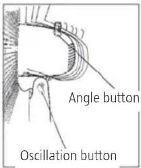
The motor unit can be tilted upwards or downwards to the desired airflow direction.
- Loosen the locking ring under the motor unit and adjust to the required angle. Tighten the locking ring (fig. 5).
- Set the desired airflow direction laterally by pulling up the oscillation button when the fan is turned to the desired angle. Activate oscillation by pressing down the oscillation button.
START/STOP AND SPEED SETTING
Start/stop and speed setting is controlled using the power switch.
O = switched off
1 = low speed
2 = middle speed
3 = high speed
ANGLE SETTING
Switch off the fan. Undo the adjuster screw slightly by turning it anti-clockwise. Set the required angle and tighten the adjuster screw.
CLEANING
- Switch off the appliance and unplug the power cord when the appliance is not in use, and before assembling/dismantling parts or cleaning.
- Keep the ventilation openings clean. Vacuum if necessary. Do not insert objects into the ventilation openings.
- Clean the appliance with a cloth or sponge, moistened with a mild detergent. Always be very careful to ensure that no water or other liquid enters the motor housing or control panel.
- Wipe off the machine with a cloth or sponge, moistened with clean water.
IMPORTANT! Do not use strong detergent or solvents.