
TPD500 - Gate Automation CHAMBERLAIN - Free user manual and instructions
Find the device manual for free TPD500 CHAMBERLAIN in PDF.
User questions about TPD500 CHAMBERLAIN
0 question about this device. Answer the ones you know or ask your own.
Ask a new question about this device
Download the instructions for your Gate Automation in PDF format for free! Find your manual TPD500 - CHAMBERLAIN and take your electronic device back in hand. On this page are published all the documents necessary for the use of your device. TPD500 by CHAMBERLAIN.
USER MANUAL TPD500 CHAMBERLAIN
AT/BA/BE/BG/CH/CY/CZ/DE/DK/ES/
FR/GB/GR/HR/HU/IE/IS/IT/LU/MT/NL/
NO/PL/PT/RO/RU/SE/SI/SK/TR/YU
Magnet A (1) = links
Manager, Regulatory Affairs
INSTRUCTIONS IMPORTANTES POUR LE MONTAGE ET L'UTILISATION
VEUILLEZ TOUT D'ABORD LIRE CES REGLES DE SECURITE IMPORTANTES

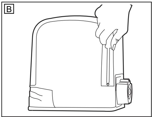
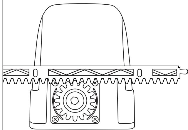
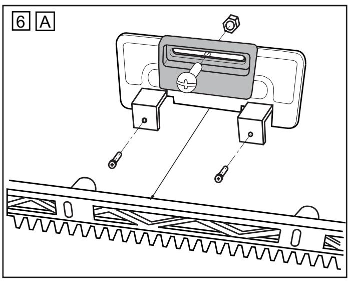
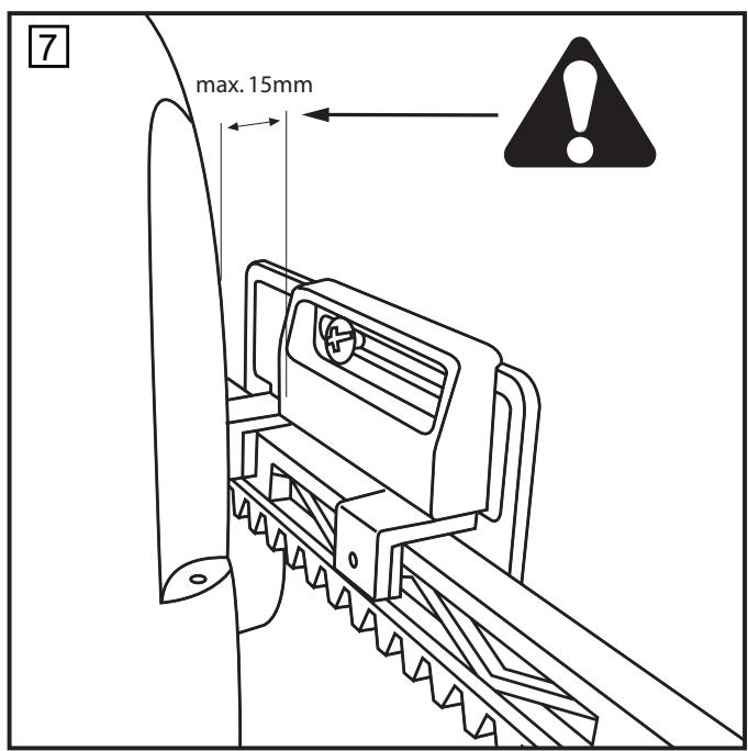
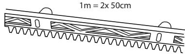
The easiest way to fit the rack bar is to first place it on the motor's drive cog, disengage the motor and, by pushing the gate further with the rack bar, screwing the bar bit by bit firmly in position. In this way, you ensure that the rail bar engages with the cog wheel in an optimum manner. While doing this, do not forget to mark each fixing point.
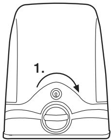
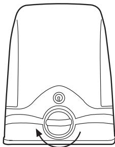
AANDRIJVING ONTGRENDELEN (HANDBEDIENING) 5
Magnet A (1) = links
Manager, Regulatory Affairs
1
3 A
B
C
5
2.
4
041ASWG-0490

771EML
41EML
ANT4X-1EML
84330EML
84333EML
84335EML
320003
CHAMBERLAIN
Anleitung und elektrische Installation HC100ML-2, HC500ML-2, TPD500
fr Instruction et installation electrique HC100ML-2, HC500ML-2, TPD500
en Instruction and electrical set up HC100ML-2, HC500ML-2, TPD500
It Istruzione e installmente elettrica HC100ML-2, HC500ML-2, TPD500
nInstruktie en electrische installmentie HC100ML-2, HC500ML-2, TPD500
es Instrucciones y instalacion electrica HC100ML-2, HC500ML-2, TPD500
pt Manuais e instalacao eletrica HC100ML-2, HC500ML-2, TPD500

www.chamberlain.de

AT/BA/BE/BG/CH/CY/CZ/DE/DK/ES/ FR/GB/GR/HR/HU/IE/IS/IT/LU/MT/NL NO/PL/PT/RO/RU/SE/SI/SK/TR/YU
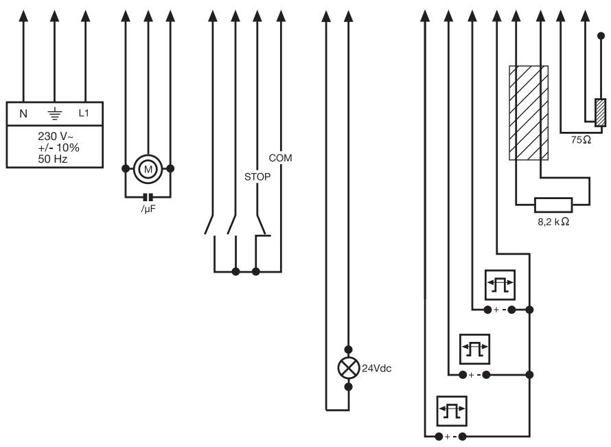
Alimentation accessories:
24 V~0,5 A max
Tension: 12/24 Volt CA/CC.
ARRET D'URGENCE (OPTION)
Tension: 12/24 Volt CA/CC.
CLIGNOTANT (OPTION) FLA24-2
BARRE PALPEUSE (OPTION)
ANTENNE (OPTION) ANT4X-1EML
Manager, Regulatory Affairs
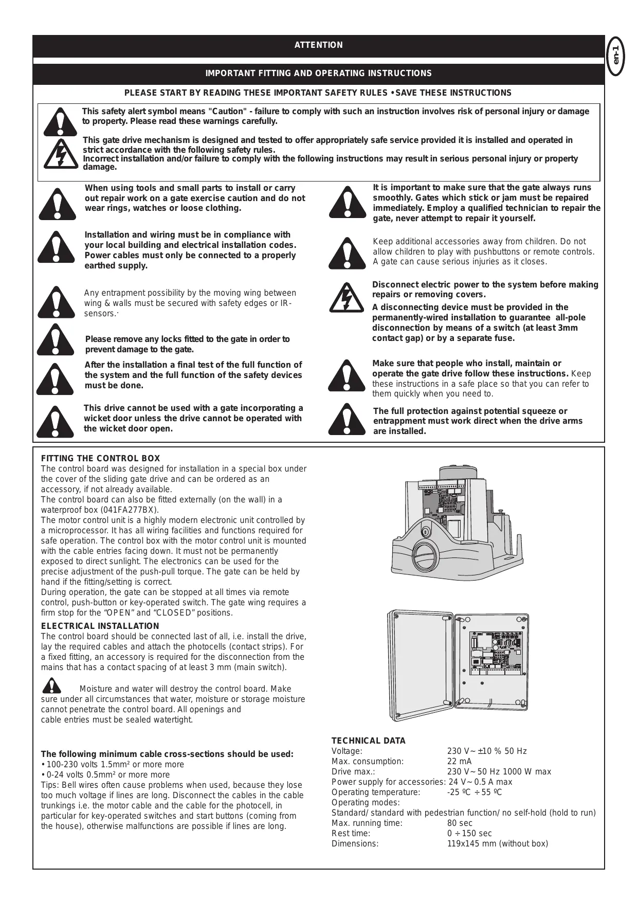
IMPORTANT FITTING AND OPERATING INSTRUCTIONS
PLEASE START BY READING THESE IMPORTANT SAFETY RULES • SAVE THESE INSTRUCTIONS


This safety alert symbol means "Caution" - failure to comply with such an instruction involves risk of personal injury or damage to property. Please read these warnings carefully.
This gate drive mechanism is designed and tested to offer appropriately safe service provided it is installed and operated in strict accordance with the following safety rules.
Incorrect installation and/or failure to comply with the following instructions may result in serious personal injury or property damage.

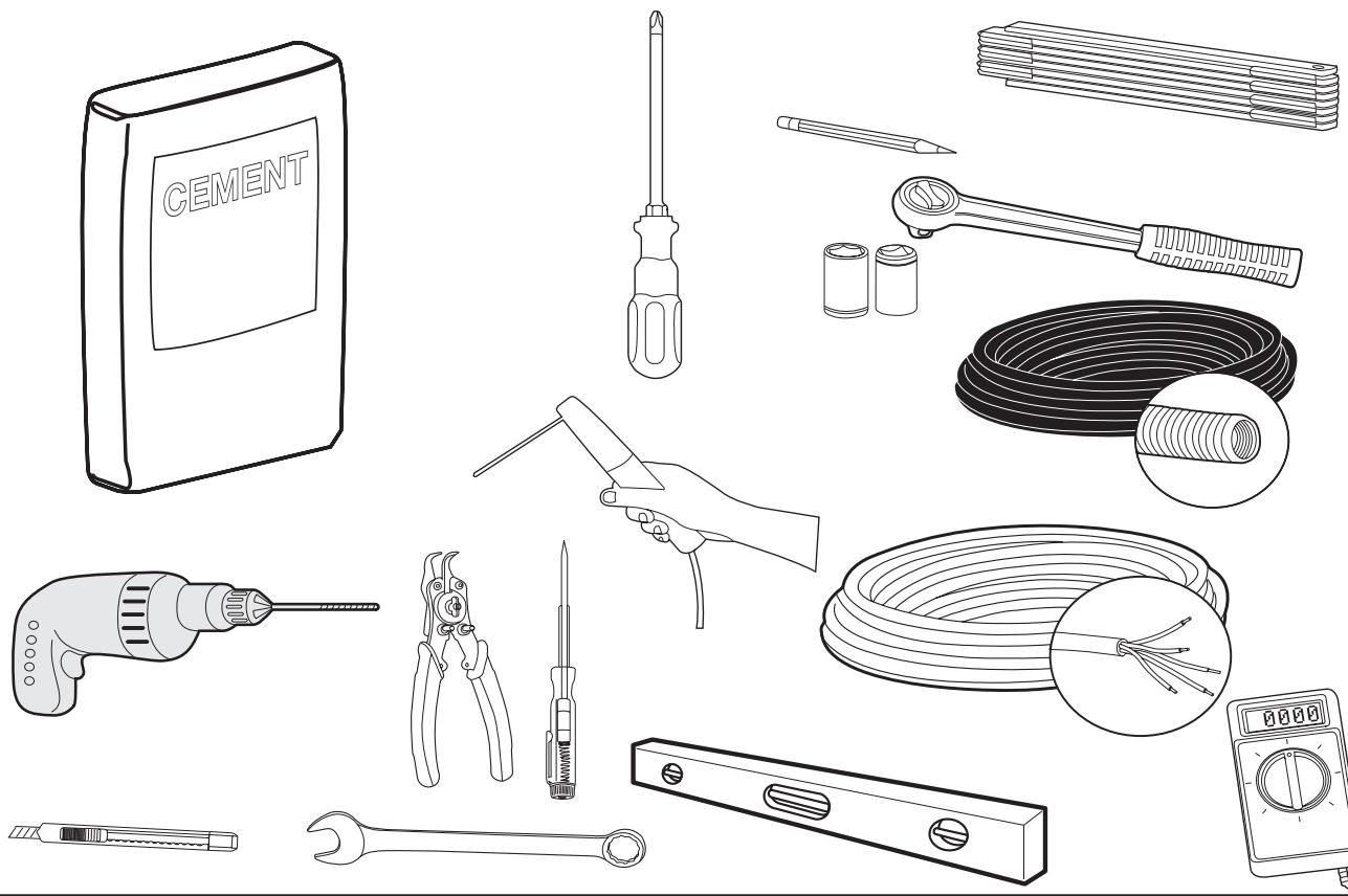
When using tools and small parts to install or carry out repair work on a gate exercise caution and do not wear rings, watches or loose clothing.

It is important to make sure that the gate always runs smoothly. Gates which stick or jam must be repaired immediately. Employ a qualified technician to repair the gate, never attempt to repair it yourself.

Installation and wiring must be in compliance with your local building and electrical installation codes. Power cables must only be connected to a properly earthed supply.

Keep additional accessories away from children. Do not allow children to play with pushbuttons or remote controls. A gate can cause serious injuries as it closes.

Any entrapment possibility by the moving wing between wing & walls must be secured with safety edges or IR-sensors.
Disconnect electric power to the system before making repairs or removing covers.

Please remove any locks fitted to the gate in order to prevent damage to the gate.
A disconnecting device must be provided in the permanently-wired installation to guarantee all-pole disconnection by means of a switch (at least 3mm contact gap) or by a separate fuse.

After the installation a final test of the full function of the system and the full function of the safety devices must be done.

Make sure that people who install, maintain or operate the gate drive follow these instructions. Keep these instructions in a safe place so that you can refer to them quickly when you need to.

This drive cannot be used with a gate incorporating a wicket door unless the drive cannot be operated with the wicket door open.

The full protection against potential squeeze or entrappment must work direct when the drive arms are installed.
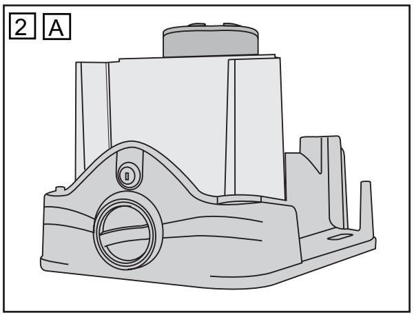
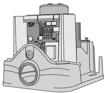
The control board was designed for installation in a special box under the cover of the sliding gate drive and can be ordered as an accessory, if not already available.
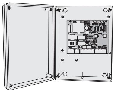
The control board can also be fitted externally (on the wall) in a waterproof box (041FA277BX).
The motor control unit is a highly modern electronic unit controlled by a microprocessor. It has all wiring facilities and functions required for safe operation. The control box with the motor control unit is mounted with the cable entries facing down. It must not be permanently exposed to direct sunlight. The electronics can be used for the precise adjustment of the push-pull torque. The gate can be held by hand if the fitting/setting is correct.
During operation, the gate can be stopped at all times via remote control, push-button or key-operated switch. The gate wing requires a firm stop for the "OPEN" and "CLOSED" positions.
ELECTRICAL INSTALLATION
The control board should be connected last of all, i.e. install the drive, lay the required cables and attach the photocells (contact strips). For a fixed fitting, an accessory is required for the disconnection from the mains that has a contact spacing of at least 3 mm (main switch).

Moisture and water will destroy the control board. Make
sure under all circumstances that water, moisture or storage moisture cannot penetrate the control board. All openings and cable entries must be sealed watertight.
The following minimum cable cross-sections should be used:
100-230 volts 1.5mm^2 or more more
- 0-24 volts 0.5 mm^2 or more more
Tips: Bell wires often cause problems when used, because they lose too much voltage if lines are long. Disconnect the cables in the cable trunkings i.e. the motor cable and the cable for the photocell, in particular for key-operated switches and start buttons (coming from the house), otherwise malfunctions are possible if lines are long.
TECHNICAL DATA
Voltage: 230 V~ ±10 % 50 Hz
Max. consumption: 22 mA
Drive max.: 230 V~50 Hz 1000 W max
Power supply for accessories: 24V 0.5A max
Operating temperature: -25 °C ÷ 55 °C
Operating modes:
Standard/ standard with pedestrian function/ no self-hold (hold to run)
Max. running time: 80 sec
Rest time: 0 ÷ 150 sec
Dimensions: 119x145 mm (without box)
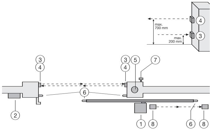
TYPICAL CONFIGURATION OF A UNIT
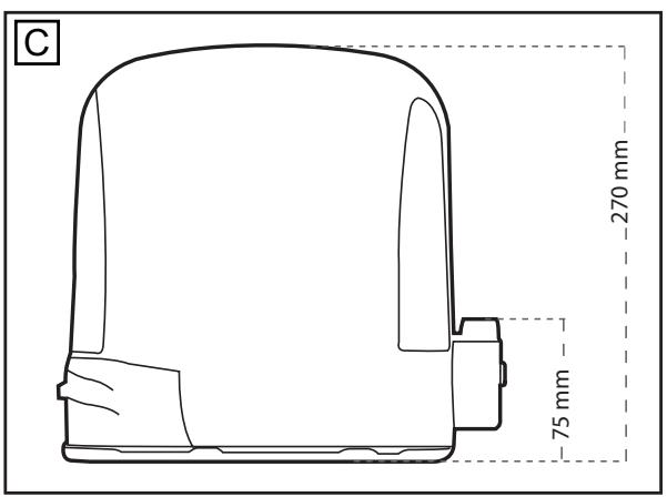
- Drive with control board
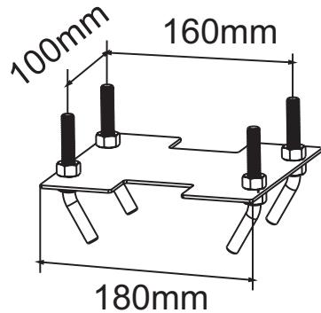
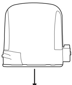
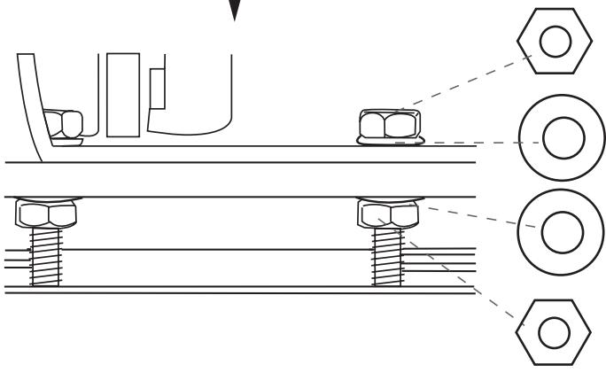
The drive is located on a height-adjustable mounting plate - Control board (if mounted externally)
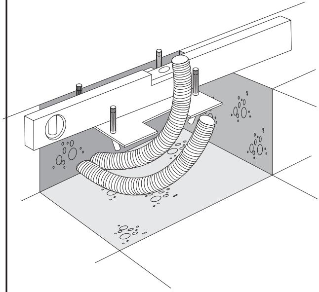
If the control board is mounted externally (external mounting box required), the cables and feeder cables must be laid correctly - photocell (771EML) 150-200 mm (optional)
First photocell. Protects people - photocell (771EML) 700 mm (optional)
Second photocell. Protects vehicles and higher objects - Flashing light
Important visual information on the movement of the gate - Contact strip (optional)
Safeguards the gate on being touched. Contact strips can be mounted on the gate or on the pillars. If the gate has openings exceeding 45mm , a contact strip is required on the pillar (accessory). If required, contact strips must be mounted at a height of up to 2.5m . - Key-operated switch (optional)
Is mounted on the outside. The gate is opened by key or by entering a number. - photocell (optional)
Safeguards the gate on opening. This photocell can be omitted if the construction itself prevents people from being present in this area. A contact strip can be fitted here as an alternative option.

The control board complies with the latest EU directives. On
of these directives specifies that the closing forces at the gate edge must not exceed 400N (40 kg) for the last 500 mm before the gate is CLOSED. Above 500 mm, the maximum force at the gate edge must not exceed 140 N (140 kg). If this cannot be ensured, a contact strip must be mounted on the gate at a height of up to 2.5 m or on the opposite pillar (EN12453).
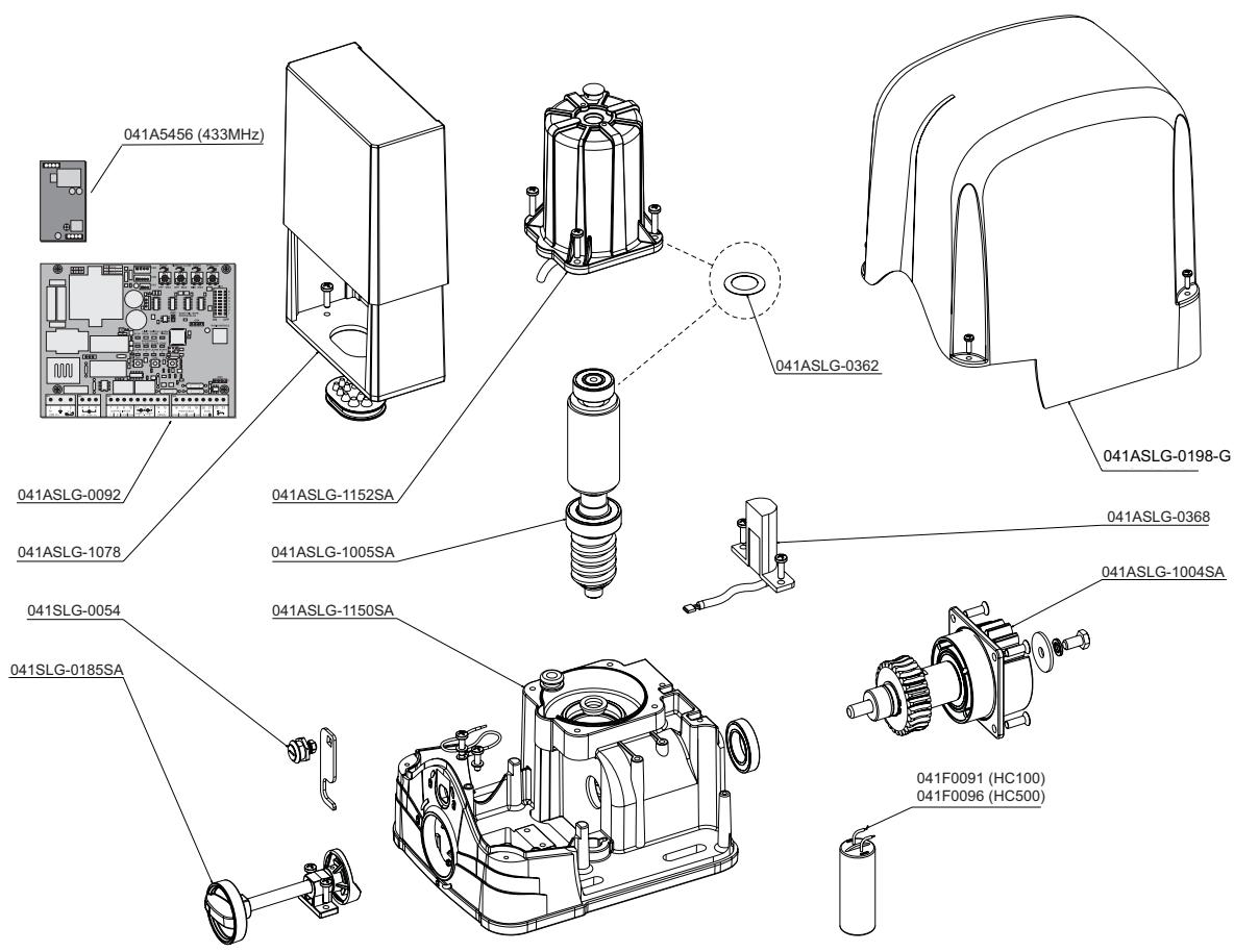
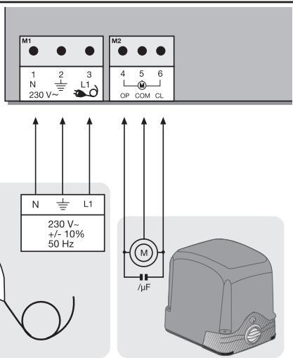
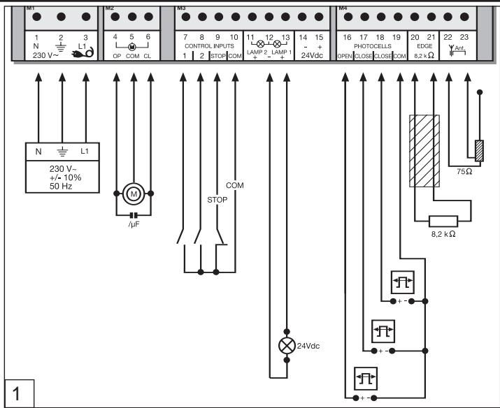
MOTOR
Connect the motor to the control board exactly as shown on the connection layout diagram.
Terminal 4 cable black
Terminal 5 cable blue
Terminal 6 cable brown
The cable for the capacitors supplied with the motors must be inserted in terminals OP and CL together with the cables for the direction of rotation. Make sure that it is connected correctly and powered sufficiently. The capacitor is responsible for the force that the motors have later on.
Note: If drives/motors other than ours
are connected, it might be required to swap the cables of terminals 4
- 6 to ensure correct operation. This is shown during "Initial
operation", if the control board does not maintain the correct moving directions. See also the Limit switch connection instructions for more information.
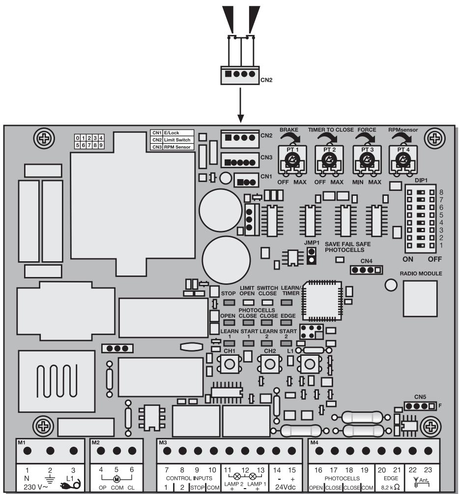
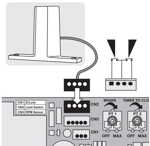
LIMIT SWITCH CONNECTION
2005 design: The cable is connected to terminal CN2 using the connector.
Other designs: There is no connector on the limit switch. On purchasing a single control board, a connector is provided with a short cable. Both cables are connected by means of a soldered connection or a block terminal. Different types of limit switch systems can be connected to the control board. The limit switch has to have 2 contacts NC (normal closed). See the illustration for the correct connection.
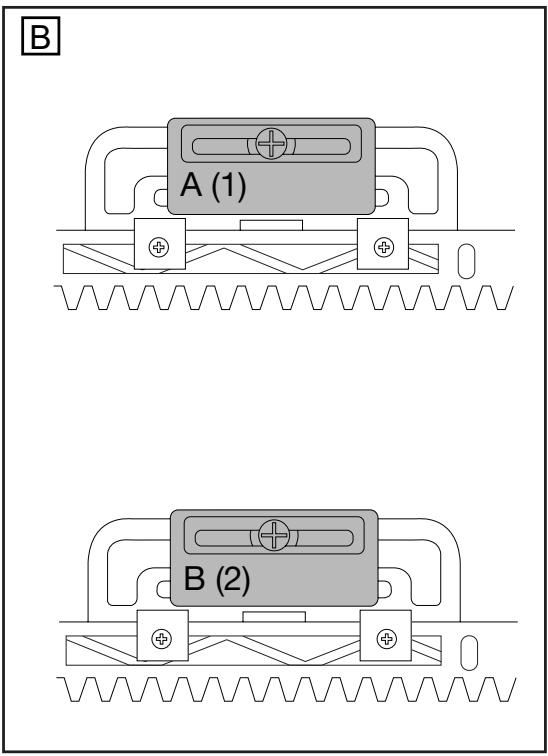
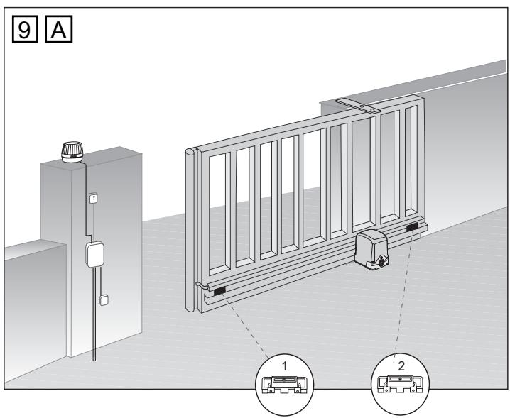
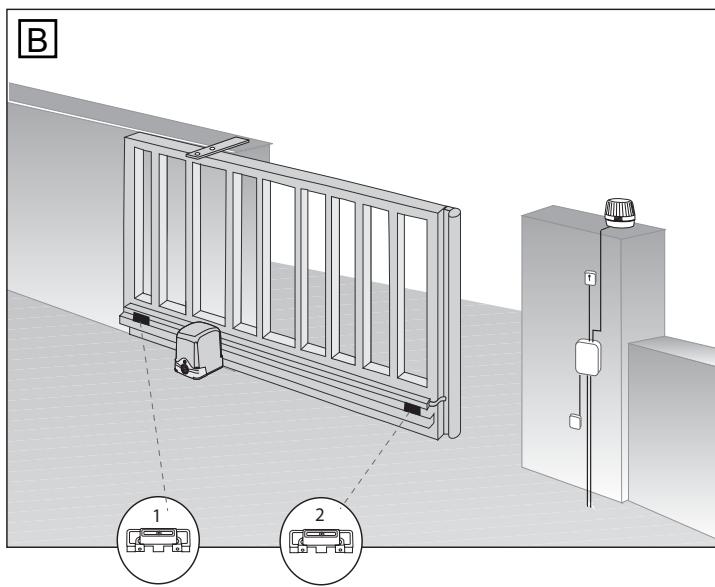
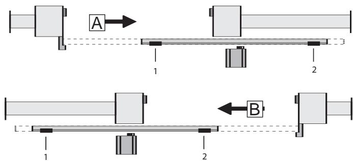
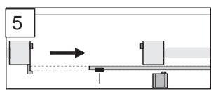
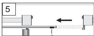
Position of the magnets on the gate for magnetic limit switch:
The magnet with the designation 1 must always be fixed on the left side of the rack bar.
The magnet with the designation 2 must always be fixed on the right side of the rack bar.
Note: The correct operation of the control LED should be rechecked before initial operation.
Note: In order to have the correct direction for OPEN, check the the setting of DIP7.
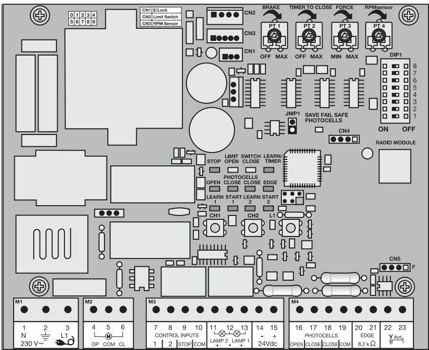
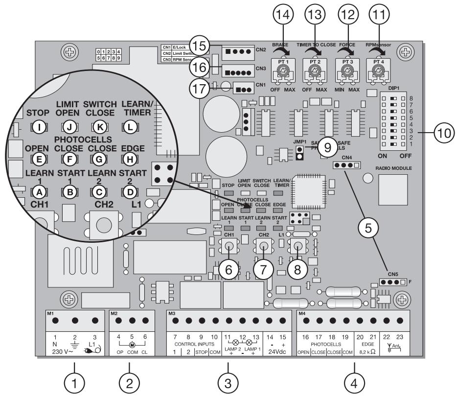
| POINT | DESCRIPTION | FUNCTION |
| 1 | M1, terminals:1,2,3 | Feeder cable |
| 2 | M2, terminals:4,5,6 | Drive |
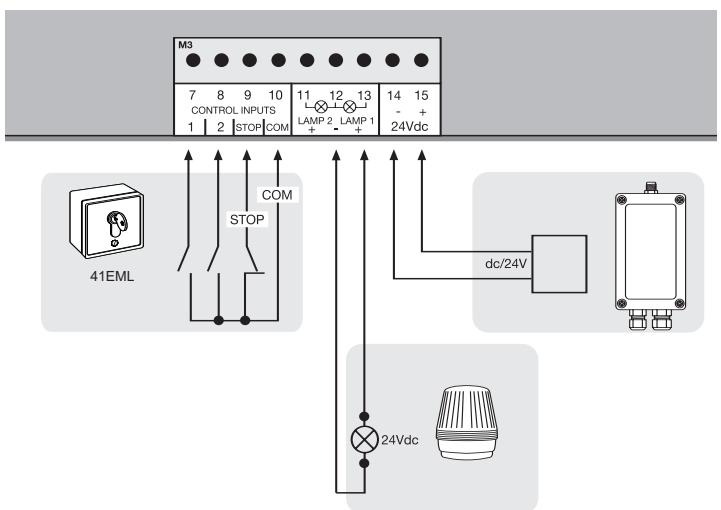
| 3 | M3, terminals:7,10 | Impulse transmitter channel 1 |
| Terminals:8,10 | Impulse transmitter channel 2 | |
| Terminals:9,10 | Emergency-stop push-button / must be bridged without switch connected | |
| Terminals:11,12 | no function | |
| Terminals:12,13 | Flashing lamp | |
| Terminals:14,15 | Connection for accessories 24V | |
| 4 | M4, terminals:16,19 | Optional photocell OPEN |
| Terminals:17,19 | Optional photocell CLOSED | |
| Terminals:18,19 | Main photocell CLOSED | |
| Terminals:20,21 | Contact strip 8.2 kilo ohms | |
| Terminals:22,23 | Antenna | |
| 5 | CN4/CN5, connector | Radio module sockets |
| 6 | CH1, pushbutton | Learn/Delete radio channel 1 |
| 7 | CH2, pushbutton | Learn/Delete radio channel 2 |
| 8 | L1, pushbutton | Learning the distance covered |
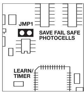
| 9 | JMP1, jumper | Programming the photocell |
| 10 | DIP1 | Dip switch block |
| 11 | PT4, potentiometer | no function |
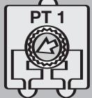
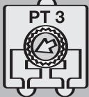
| 12 | PT3, potentiometer | Force setting |
| 13 | PT2, potentiometer | Automatic closing |
| 14 | PT1, potentiometer | Brake |
| 15 | CN2, connector | Magnetic limit switch |
| 16 | CN3, connector | no function |
| 17 | CN1, connector | no function |
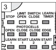
DESCRIPTION OF THE LEDs
| RED LEDs should be switched off. Indication of faults to be rectified; this does not apply to failsafe photocells not connected. (see "photocell" description) | |
| (Example: short circuit, photocells and/or contact strip) | |
| POINT | DESCRIPTION |
| LED A | RED Learn/Delete radio channel 1 |
| LED B | RED Start impulse channel 1 |
| LED C | RED Learn/Delete radio channel 2 |
| LED D | RED Start impulse channel 2 |
| LED E | RED photocell active for OPEN |
| LED F | RED photocell active for CLOSE |
| LED G | RED photocell active for CLOSE |
| LED H | RED contact strip |
| LED I | GREEN stop |
| LED J | YELLOW limit switch gate OPEN |
| LED K | YELLOW limit switch gate CLOSED |
| LED L | RED learn program (distance covered) |
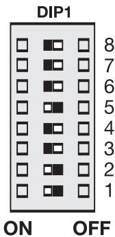
| PROGRAMS The control board has 3 operating modes (programs). The desired program is set using the dip switch “ON” or “OFF”. | ||
| DIP 1 | On | Assigned to various drive operating modes. (see separate table) |
| DIP 2 | Off | |
| DIP 3 | On | Soft stop (slow run) is active The soft stop is activated 2 seconds before the limit switch is reached. The drive stops only when the limit switches have been reached or as soon as the maximum soft stop phase (10 seconds) has expired. |
| Off | ||
| DIP 4 | On | Soft stop (slow run) is disabled. The drive shuts down immediately in both directions OPEN/CLOSED as soon as the limit switches have been reached. |
| Off | ||
| DIP 5 | On | Setting for Chamberlain fails safe photocells (771EML), complies with EN60335-2-103 |
| Off | Setting for Chaimberlain photocells (263EML) or others | |
| DIP 6 | On | Preflash function of flashing light 2 seconds before the drive starts. |
| Off | Preflash function disabled | |
| DIP 7 | On | see B |
| Off | see A | |
| DIP 8 | no function | |
Only modify settings when control bord is disconnected. Otherwise modifications will not be accepted!!!
POTENTIOMETER
PT1 (TRIMMING POTENTIOMETER 1): BRAKE
When the gate reaches its limit switch, the drive shuts down. Depending on weight and function of the gate, it may continue to move on a bit further before stopping. The brake function is for the active braking of the gate in order to minimise this additional movement. Left stop = brake OFF.
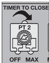
PT2 (TRIMMING POTentiometer 2): AUTOMATIC CLOSING (TIMER TO CLOSE)
The waiting time for the gate for GATE OPEN can be defined. The gate is closed 0-150 sec. after the set time expires. Only possible if failsafe photocell is connected (771EML). (Not possible for self-hold and channel separation)
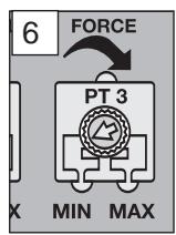
PT3 (TRIMMING POTENTIOMETER 3): FORCE SETTING
Definition of the force with which motor is to operate. The required force depends on weight and function of the gate.
PT4 (TRIMMING POTENTIOMETER 4): RPM SENSOR
no function
PT1
PT2
PT3
PT4


Only modify settings when control bond is disconnected. Otherwise modifications will not be accepted!!!
| Separate table for setting the operating modes | |||||
| DIP1 | DIP2 | DIP3 | Impulse transmitter/channel 1 | Impulse transmitter/channel 2 | |
| Standard | ON | ON | OFF | 1. impulse opens, the next one stops, the next one closes, the next one opens | 1. impulse opens for pedestrians, gate is moved open for 10 seconds (fixed), next impulse closes, next impulse opens again for pedestrians. |
| Impulse during closing opens | |||||
| Impulse during the rest closes the gate immediately | |||||
| Standard & pedestrian function | OFF | ON | OFF | 1. impulse opens, the next one closes, the next one opens | 1. impulse opens for pedestrians, gate is moved open for 10 seconds (fixed) |
| Impulse during the rest closes the gate immediately | |||||
| No self-hold (hold to run) | OFF | OFF | OFF | Permanent signal required for opening, letting go stops | Permanent signal required for closing, letting go stops |
| Radio disabled, safety equipment disabled, limit switches are active | Radio disabled, safety equipment disabled, limit switches are active | ||||
Note: If important safety equipment ( photocell/contact strip) is damaged, constantly active (switching) or if programmed equipment is not connected, the control board operates without self-hold (hold to run). See description. For any corrections, check the status LEDs or see functional description and "Frequently asked questions".
ACCESSIONS
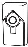
PHOTOCELLS (OPTIONAL)
The photocells are for safeguarding the gate and must be used. The fitting location depends on the gate's design. EN12453 specifies that a pair of photocells must be installed at a height of 200mm ; a second pair must be installed in the same position at a height of 700mm . A third pair of photocells can be optionally installed. The photocells consist of a transmitter and a receiver and must be opposite each other. The housing of the photocell (plastic) can be opened using a screwdriver. The photocell is mounted on the wall using small screws and wall plugs. It is possible to use two different photocell systems. (see Dip switch description). To enable the "Automatic closing" function, the Chamberlain fails safe photocell must be installed. A combination of photocells is not possible. The Chamberlain fails safe system (2-cable system) has small LEDs (light) that can be seen from the outside on both sides to indicate the status of the photocell. Two Chamberlain fails safe photocell models are available. The one model is ideal for walls lying opposite. The other model is ideal for the inside of the gate, because fittings are already available.
Diagnosis at the Chamberlain fails safe photocell
LED constant = OK
LED flashes = photocell disables control board
LED off = no current, incorrect connection or polarity
Diagnosis on the control board
LED off = OK
LED on constantly = control board disables
LED flashes = OK no photocell connected
Cable cross-section: 0.5mm^2 or more.
Voltage: 12/24 volts AC/DC.
Do not use any fixed copper lines. Do not lay any 230 volt cables in parallel and do not lay any 2 cables in the same cable trunking.
Programming of failsafe photocells model 771EML
1.Before the Initial Setup
2.When connecting or removing photocell(s)
- Switch off control board (disconnect from current)
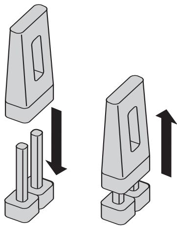
- Slip jumper on designated pins
- Dipswitch 5 to "ON"
- Connect photocell(s) according illustration
- Reconnect control board, wait short-time
- Pull jumper, wait short-time
Done! (The number of photocells connected are stored)
Programming of relay photocells such as 263EML
The control board must be disconnected from the mains for a few seconds. All terminals to which no photocell is connected must be bridged with COM. (16-19, 17-19, 18-19). The power supply for the relay photocell of terminals 14-15. Dip switch 5 must be at OFF. The jumper must be unplugged.
Note: Relay photocells are no longer permitted for new installations as per EN12978, because they cannot perform self-checks (failsafe).
Operation without photocells

Not permitted for normal operation. In this case contact
strips must safeguard the gate. The control board must be disconnected from the mains for a few seconds. Terminals 16-17-18-19 must all be bridged. Dip switch 5 must be at OFF. The jumper must be unplugged.
Note: It is NOT possible to combine different photocell types.
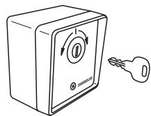
PUSHBUTTON / KEY-OPERATED SWITCH (OPTIONAL)
The control board / drive can be activated using various inputs. This can be done using a hand-held transmitter or key-operated switch (Terminals 7 + 10).
Hand-held transmitter = see Teaching the hand-held transmitter
Switch input 1 = input control 1. Normal operation
Switch input 2 = input control 2. Active for special settings (see Dip switch description)
EMERGENCY STOP (OPTIONAL)
A switch can be connected to stop or disable the unit. The movement of the wings is stopped immediately. Terminals 9 and 10 must be bridged if no switch is installed.
Cable cross-section: 0.5mm^2 or more.
Voltage: 12/24 volts AC/DC.
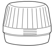
FLASHING LAMP (OPTIONAL)
A flashing lamp can be connected to the control board. It warns when the gate is being moved. The flashing light should be fitted as high as possible and in good clear view. The control board emits a constant signal that the lamp converts to a flashing signal.
Cable cross-section: 0.5mm^2 or more.
Voltage: 24 V DC
24 VDC - OUTPUT
For relay infrared senors or other devices (e.g. receivers) max.500 mA

Do not use any fixed copper lines. Do not lay any 230 volt
cables in parallel and do not lay any 2 cables in the same cable trunking.
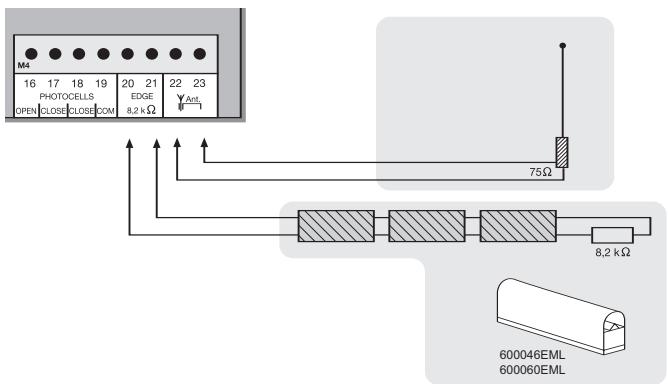
CONTACT STRIP (OPTIONAL)
A contact strip working according to the 8.2 kilo ohm principle can be connected to the control board, i.e. a 8.2 kilo ohm test resistor is attached to the end of the contact strip. It ensures that the electric circuit is monitored permanently. The control board is supplied with an 8.2 kilo ohm resistor installed. Several contact strips are connected in series.
Cable cross-section: 0.5mm^2 or more.
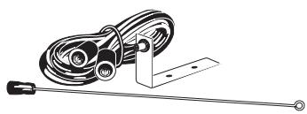
ANTENNA (OPTIONAL) ANT4X-1EML
The control board is standard-equipped with a wire antenna. An external antenna (accessory) can be connected to terminals 22 and 23. A larger range (radio) can thus be achieved. Mount the antenna as high as possible.

Do not use any fixed copper lines. Do not lay any 230 volt cables in parallel and do not lay any 2 cables in the same cable trunking.
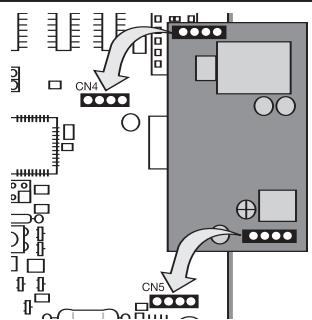
RADIO MODULE (PLUGGED)
To operate the control board via radio remote control, a radio module must first be installed in slots CN4/CN5.
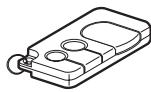
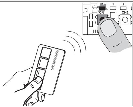
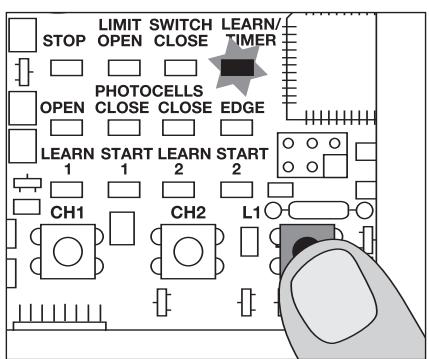
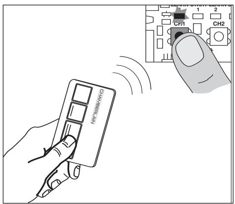
TEACHING / DELETING THE HAND-HELD TRANSMITTERS
Press button CH1. The LED "Learn1" lights up red. Now press one of the transmitter's button for approx. 5 seconds. The LED "Learn 1" flashes now. Finished. Proceed in exactly the same way for CH2. However, now press one of the transmitter's buttons that has not yet been assigned. Up to 128 hand-held transmitters can be programmed in this way.
To delete the programmed transmitter setting, simply press button CH1 until the LED goes out. Proceed in the same way for CH2.
Proceed step by step. If you are not sure, start again at the beginning. Take sufficient time to make these settings.
- Are all components required for operation connected? Motor(s), photocell (!), flashing light, push-button or switch etc?
- Make sure that nobody is present in the range of the gates.
- Check whether the LEDs (lamps) are working correctly or whether they are blocking a function. RED LEDs should be off, green LEDs should be on. (with the exception of the LEDs for the limit switch status - yellow)
- Set the dip switch to the standard program, if not already done on delivery: 1 = "ON" , 2 = "ON" , 3 = "OFF" .
Any changes can be made late. (see Dip switch description) - Dip switch 7 determines the direction of opening (see Dip switch description)
- Set the force at the potentiometer "FORCE " to max. 30% . Even lower if the gates are very light. Try before correcting. Only increase the force in small steps.
- Switch off control board (disconnect from current)
7.1 Slip jumper on designated pins
7.2 Dipswitch 5 to "ON"
7.3 Connect photocell(s) according illustration
7.4 Reconnect control board, wait short-time
7.5 Pull jumper, wait short-time
Done! The LED(s) of the photocell(s) connected stay(s) out.
The LED(s) of the photocell(s) not connected will flash.
Programming the time for the covered distance
- Unlock the gate and move it manually to the limit switch. This is how you check whether the limit switch for OPEN/CLOSED is displayed at the correct LED
. If the right limit switch has been activated, the corresponding LED goes out.
- Move the gate again manually between the limit switches "OPEN" and "CLOSED" and lock it. (Both limit switches must remain free.) 3. Press button L1 briefly (1 second), the gate opens. If the gate reaches the "OPEN" limit switch, it stops briefly and then closes again automatically. Once the gate reaches the "OPEN" limit switch, the programming process is completed.
ATTENTION: If the gate closes instead of opening, dip switch 7 must be moved to the other position! Then restart programming again from the beginning with step 1.
The time for the required covered distance has now been programmed. The soft stop (slow run) is programmed automatically approx. 4-5 seconds before the limit switch is reached. It can then be activated via dip switch. (see Dip switch description)
Completion of the installation/programming:
Once the covered distance is programmed, the hand-held transmitters can be programmed (not required for kits) or
- Start the gate with the hand-held transmitter or a connected button and observe the process. Close the gate again WITHOUT having made any settings.
Note1: The gate does not react (see photocell description jumper). Note2: If the gate now only reacts with one switch (terminals 7+10), either the radio has not been programmed/is not available or the radio module is not plugged in correctly. - If the gate does not close completely by itself, adjust the potentiometer to other values, adapted to fit the experience value from the test. (force correction)
- Now start a second attempt and proceed as above. Close the gate first before you make any settings.
- Once all settings have been made, check the function of photocells, buttons, flashing lamp, hand-held transmitter, accessories etc. If you desire automatic closing, turn the "TIMER TO CLOSE" potentiometer in clockwise direction. You can set the rest time between 0 and 150 seconds, as desired.
Also make these settings with the gate closed. - Show all persons that use the gate how the gate moves, how the safety functions work and how to operate the drive by hand.
| Frequently asked questions | ||
| How long is the probable service life of a gate opener? | When used for private purposes, a correctly installed gate opener can operate perfectly for in excess of 10 years. Both the gate and the gate opener must be checked regularly and serviced in accordance with their respective instructions. | |
| How long does it take to install a gate opener? | Depending on your specific technical skills, the installation of the mechanical components can take approx. 3 to 4 hours. Firstly, the gate needs to be properly prepared such that installation work can commence. The electrical connection work takes approx. 1 to 2 hours. Each user should be instructed for at least 30 minutes with regard to the operation of the gate opener, whereby its functionality should be demonstrated and safety aspects, protective facilities and procedure in case of power failure should all be explained. | |
| What happens in case of power failure? | All Chamberlain gate openers are equipped with a release system by means of which the gate can be operated manually in case of power failure. | |
| Is it possible to open just one wing of the gate (pedestrian mode)? | Yes, it is possible. This process can be operated via remote control (a 2-channel remote control is the minimum requirement here) or via switch operation (see "Standard" operation mode setting). | |
| Gate opener does not function / does not respond when button is pressed. | 1. Connection to button is loose. 2. STOP switch connection is loose; STOP LED is off. 3. Obstacle is blocking photocell in direction of movement. 4. Safety edge is damaged or has encountered an obstacle. 5. Gate opener is still released. | 1. Check button and COM connections. 2. Check STOP switch connections (STOP and COM). 3. Remove obstacle. 4. Remove obstacle and check connections and wiring. 5. Lock gate opener. |
| Immediately after the gate has started moving, it stops and reverses. | Obstacle in area of gate. | Check area of gate for objects |
| The gate opener does not open the gate fully. | 1.Has the running time of the controller been set correctly? 2.Has the force been set correctly? | 1.Reprogram as required – plus approx. 3 seconds. 2.Correct force setting (gate opener runs somewhat slower in windy conditions). |
| The gate opener hums slightly but has no force | 1. Capacitor is not correctly connected to the brown and black cable. 2. Force has not been set. 3. The gate opener has been released. | 1. Check wiring of capacitor. 2. Turn force potentiometer in a clockwise direction. 3. Lock gate opener. |
| The controller doesn't respond when I alter the Dip-switches. | Disconnect controller from power supply, then alter Dip-switches. | |
| The gate opener only works when I press and hold the button on the remote control. | 1. Controller in 'hold to run' operating mode. 2. A safety facility is not working correctly (photocell, safety edge). | 1. Disconnect controller from power supply, then alter Dip-switches. 2. Observe LEDs; find and rectify fault. |
| “Timer to close” doesn't work. | 1. Only works if the 2-cable photocell 770E(ML) or 771E(ML) has been installed. 2. Then turn “timer to close” potentiometer in a clockwise direction. | |
| The gate opener doesn't respond at all, although the controller has been connected (LEDs are on). | 1. Remote control has not been programmed. 2. LEDs indicate a fault. 3. Photocell connected incorrectly. 4. Jumper between STOP and COM missing. 5. Motor terminal possibly not connected properly. | 1. Programming remote control. 2. Find and rectify fault(s) (see description of LEDs). 3. Check photocell connection / programming. 4. Connect simple jumper. 5. Check terminals and connections. |
| The gate opener doesn't respond at all; no LED is on. | Possibly power failure. | 1. Check conductor and zero conductor. 2. Check house fusing. |
| The gate opener stops suddenly and then restarts only after a lengthy pause. | If the gate is operated constantly, the motor will reach its cut-off temperature - protective facility - as the gate opener is not designed for permanent operation. | Allow motor sufficient time to cool (min. 15 minutes). |
| The gate must follow a slope. | Not recommended! Change gate! The gate can move in an uncontrolled (dangerous) manner if the gate opener has been released. A stronger force is needed in the upwards direction of the slope and then, in the opposite direction, the gate opener's force is too strong. | |
| The remote control's range is too short. | The installation of an external aerial is recommended as the controller with the short cable aerial is located either behind the post or near ground level in most cases. The optimum location of the aerial is as high as possible in all cases. An appropriate aerial with installation kit can be obtained from Chamberlain as an accessory with the product ref. no. ANT4X-1EML. | |
| The force setting has been altered, but no difference is apparent. | Disconnect the controller from the power supply for a few seconds in order to activate the control board's self-diagnosis functionality. | |
| The control board does not work any more using the hand-held transmitter, only with the switch and even then only as long as a button is pressed and kept pressed.Open with push-button (1) or CLOSE with push-button (2) | 1.Dip switch setting not as desired2.A safety photocell, a contact strip or the stop disables the control board3.Only one photocell was connected for OPEN | 1.Correction of the dip switch, elimination of fault required. If the fault cannot be repaired, it will be necessary to “reset” and reprogram (see photocell)2.At least one photocell must be connected and activated for CLOSED or OPEN & CLOSED. |
| The unit does not close automatically, it OPENS automatically | Check setting of Dipswitch 7 | Change setting of Dipswitch 7 |
| Control board does not work with hand-held transmitter | 1.Hand-held transmitter not programmed2.An photocell blocks | 1.Program hand-held transmitter2.Checked photocells |
| Gate can only be opened | 1.photocell blocks2.Dip switch setting not as desired | 1.First limit switch gate OPENFunction and connection of the limit switches must be checked2.Checked dip switch |
| The control board is not running | No covered distance learned | Learn covered distance.See Initial operation |
| The wing does not open completely for the soft stop | 1.Insufficient force in the event of high wind loads(entire gates)2.Gate sluggish/heavy | 1.Rest force (increase)2.Improve ease of movement3.Program control board without soft stop |
| (Remote controlled) universal receiver does not work | Observe polarity (terminals 14/15) | Swap "+" and "-" cables |
Declaration of Conformity
Automatic Gate Opener Models HC100ML-2, HC500ML-2 Series
are in conformity to the applicable
sections of StandardsEN300220-3 • EN55014 • EN61000-3 • EN60555, EN60335-1 • ETS
300 683 • EN60335-1: 2002 • EN60335-2-103: 2003 • EN55014-1: 2000 + A1 + A2 • EN55014-2: 2001 • EN61000-3-2: 2000 • EN61000-3-3: 1995 + A1 • EN 301 489-3, V1.3.1 • EN 300 220-3 V1.1.1 • EN13241-1
per the provisions & all amendments of the EU Directives 2006/95/EC, 2004/108/EC, 1999/5/EG
Declaration of Incorporation
Automatic Gate Opener Models when installed and maintained according to all the Manufacturer's instructions in combination with a Gate, which has also been installed and maintained according to all the Manufacturer's instructions, meets the provisions of EU Directive 89/392/EEC and all amendments.
I, the undersigned, hereby declare that the equipment specified above and any accessory listed in the manual conforms to the above Directives and Standards.


Chamberlain GmbH D-66793 Saarwellingen Mai,2008
IMPORTANT ISTRUZIONI PER IL MONTAGGIO E L'USO
PER PRIMA COSA LEGGERE QUESTE IMPORTANTI NORME DI SICUREZZA!

BESCHRIJVING VAN DE LED's
NOODSTOP (OPTIONEEL)
CONTACTLIJST (OPTIONEEL)
Protege la puerta en caso de contacto. Las regletas de contactoSEOSEOSEOSEOSEOSEOSEOSEOSEOSEOSEOSEOSEOSEOSEOSEOSEOSEOSEOSEOSEOSEOSEOSEOSEOSEOSEOSEOSEOSEOSEOSEOSEOSEOSEOSEOSEOSEOSEOSEOSEOSEOSEOSEOSEOSEOSEOSEOSEOSEOSEOSEOSEOSEOSEOSEOSEOSEOSEOSEOSEOSEOSEOSEOSEOSEOSEOSEOSEOSEOSEOSEOSEOSEOSEOSEOSEOSEOSEOSEOSEOSEOSEOSEOSEOSEOSEOSEOSEOSEOSEOSEOSEOSEOSEOSEOSEOSEOSEOSEO SEOEO SEOEO SEOEO SEOEO SEOEO SEOEO SEOEO SEOEO SEOEO SEOEO SEOEO SEOEO SEOEO SEOEO SEOEO SEOEO SEOEO SEOEO SEOEO SEOEO SEOEO SEOEO SEOEO SEOEO SEOEO SEOEO SEOEO SEOEO SEOEO SEOEO SEOEO SEOEO SEOEO SEOEO SEOEO SEOEO SEOEO SEOEO SEOEO SEOEO SEOEO SEOEO SEOEO SEOEO SEOEO SEOEO SEOEO SEOEO SEOEO SEOEO SEOEQ
- Cerradura a llave externa (optional)
Manager, Regulatory Affairs
INSTRUÇOES IMPORTANTES PARA A MONTAGEM E UTILIZAZão
COMECE POR LER ESTAS NORMAS DE SEGURANÇA IMPORTANTES

2004/108/CE
2006/95/CE
1999/5/CE