
SLY1000 - Gate Automation CHAMBERLAIN - Free user manual and instructions
Find the device manual for free SLY1000 CHAMBERLAIN in PDF.
User questions about SLY1000 CHAMBERLAIN
0 question about this device. Answer the ones you know or ask your own.
Ask a new question about this device
Download the instructions for your Gate Automation in PDF format for free! Find your manual SLY1000 - CHAMBERLAIN and take your electronic device back in hand. On this page are published all the documents necessary for the use of your device. SLY1000 by CHAMBERLAIN.
USER MANUAL SLY1000 CHAMBERLAIN
Magnet A (1) = links
Manager, Regulatory Affairs
Chamberlain GmbH
D-66793 Saarwellingen
January, 2009

Babaa PekkhoH
INSTRUCTIONS IMPORTANTES POUR LE MONTAGE ET L'UTILISATION
VEUILLEZ TOUT D'ABORD LIRE CES REGLES DE SECURITE IMPORTANTES

Manager, Regulatory Affairs
Chamberlain GmbH
D-66793 Saarwellingen
Janvier, 2009

Babba P. KeckhoH
IMPORTANT FITTING AND OPERATING INSTRUCTIONS
PLEASE START BY READING THESE IMPORTANT SAFETY RULES • SAVE THESE INSTRUCTIONS


This safety alert symbol means "Caution" - failure to comply with such an instruction involves risk of personal injury or damage to property. Please read these warnings carefully.
This gate drive mechanism is designed and tested to offer appropriately safe service provided it is installed and operated in strict accordance with the following safety rules.
Incorrect installation and/or failure to comply with the following instructions may result in serious personal injury or property damage.

When using tools and small parts to install or carry out repair work on a gate exercise caution and do not wear rings, watches or loose clothing.

It is important to make sure that the gate always runs smoothly. Gates which stick or jam must be repaired immediately. Employ a qualified technician to repair the gate, never attempt to repair it yourself.

Installation and wiring must be in compliance with your local building and electrical installation codes. Power cables must only be connected to a properly earthed supply.

Keep additional accessories away from children. Do not allow children to play with pushbuttons or remote controls. A gate can cause serious injuries as it closes.

Any entrapment possibility by the moving wing between wing & walls must be secured with safety edges or IR-sensors.

Disconnect electric power to the system before making repairs or removing covers.

Please remove any locks fitted to the gate in order to prevent damage to the gate.
A disconnecting device must be provided in the permanently-wired installation to guarantee all-pole disconnection by means of a switch (at least 3mm contact gap) or by a separate fuse.

After the installation a final test of the full function of the system and the full function of the safety devices must be done.

Make sure that people who install, maintain or operate the gate drive follow these instructions. Keep these instructions in a safe place so that you can refer to them quickly when you need to.

This drive cannot be used with a gate incorporating a wicket door unless the drive cannot be operated with the wicket door open.

The full protection against potential squeeze or entrappment must work direct when the drive arms are installed.
Contents: General Information on Installation and Use:
Details of Contents: Page 1
Before You Begin: Page 2
Check List: Page 2, fig1 -4
Overview of Installation: Page 2
Installation of Rack Bar:
Page 2, fig.7
Installation of Base Plate:
Page 2, fig. 6 A B
Mounting Drive on Base Plate:
Page 2, fig. 6
Drive Release Mechanism:
Page 2, fig. 8
Limit Switches: Page 2, fig. 9 + 12
Initial Operation:
Page 3, fig. 10
Maintenance Work: Page 3, fig. 11
Technical Data: Page 3
CE Conformity Certificate: Page 3
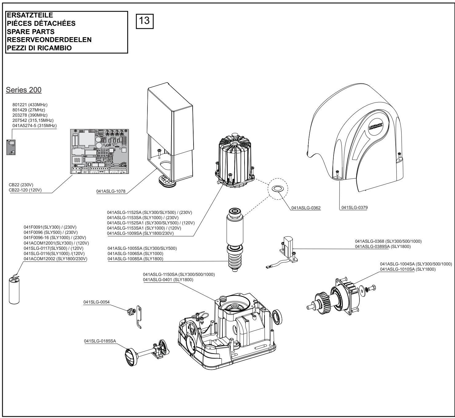
Replacement Parts: fig. 13
Contents in SLY300, SLY500, SLY1000, SLY1800 packs
(1) Drive motor (1x)
(2) Capacitor (1x)
(3) Limit switch A or (1) (1x)
(4) Limit switch B or (2) (1x)
(5) Base plate for drive motor (1x)
(6) Accessories bag
Additionally for models: SLY300E, SLY500E, SLY1000E, SLY1800E
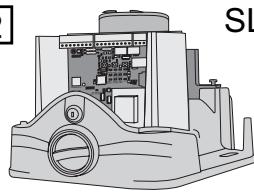
(7) Control unit with housing (pre-installed as standard for right-hand installation) (1x)
Additionally for models: SLY300K, SLY500K, SLY1000K, SLY1800K
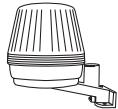
(8) Flashing lamp (1x)
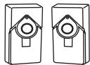
(9) Light barrier (pair)
(10) Radio (1x)
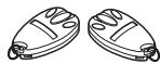
(11) Handset 433MHz (2x)
(12) Key-operated aerial (1x)
(13) External Antenna (1x)
The sliding gate drive can be activated via push Buttons, key-operated switches (radio) or remote control; once the drive has been disengaged with the appropriate key, the gate can be opened by hand. The sequence of functions initiated by a command issued via a remote control, push-button, etc. depends on how the control's electronic system has been set.
BEFORE YOU BEGIN
There are many factors that are key to the choice of the right sliding gate drive. Assuming the gate is in good working order, the most difficult aspect is getting the gate to move. Once the gate is in motion, force requirements are in the main significantly reduced.
- Gate size: Gate size is a very important factor. A light yet long gate (long = +5m) needs a far greater force to set it in motion than a short, heavy gate does.
WIND CAN BRAKE A GATE'S MOVEMENT OR MAKE IT HARD TO MOVE, THUS INCREASING FORCE REQUIREMENTS SIGNIFICANTLY.
- Gate weight: Gate weight is only an approximate indicator the actual relevance of which can vary greatly. Example: A light gate that slides poorly is likely to need a stronger drive than a heavy, smooth-sliding gate.
- Temperature: Low outdoor temperatures make it difficult or, in some cases, impossible to get the gate moving due, for instance, to changes in the ground conditions. In such cases, a stronger drive again might be necessary. High outdoor temperatures can cause the thermal protection mechanism to be activated sooner.
- Operating frequency / Duty cycle: Sliding gate drives have a maximum duty cycle of approx. 30% (e.g. 30% per hour). CAUTION: The drives were not designed to be run for the maximum duty cycle on a regular basis (permanent operation). If the drive gets too hot, it switches itself off until it has cooled down to activation temperature. The outdoor temperature and the gate itself are key factors determining the drive's actual duty cycle
- Safety: A sliding gate drive has to be fitted with a flashing lamp, contact strips and, if necessary, with additional light barriers as safety features. Please ensure that you comply with the standards and regulations relevant to your particular case.
- Control unit: The control unit was developed specifically with safety aspects in mind. It is already located under the drive hood and wired up for right-hand installation as standard (motor to the right of the gate).
CHECK LIST - PRE-INSTALLATION WORK 1 - 4
Prior to actual installation, please check that you have been provided with all the parts indicated within the scope of supply. 1 2 3 Make sure your gate system is in good working order.
The gate must run smoothly, not jerkily and not make contact with the ground at any point. Bear in mind that the ground can be several centimetres higher in winter. The gate needs to be stable with as little play as possible to prevent any lateral movement from occurring. The easier the gate moves, the more sensitive the force setting needs to be.
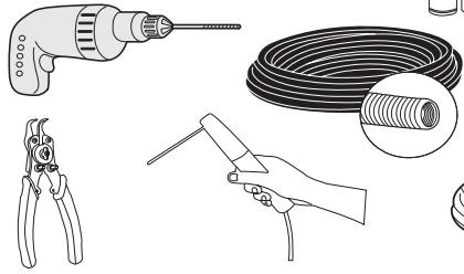
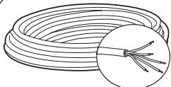
Make a note of the materials you still need and make sure you obtain them prior to installation - adhesive anchors (strong plugs), screws, stops, cable, distributor boxes, tools, etc. 4
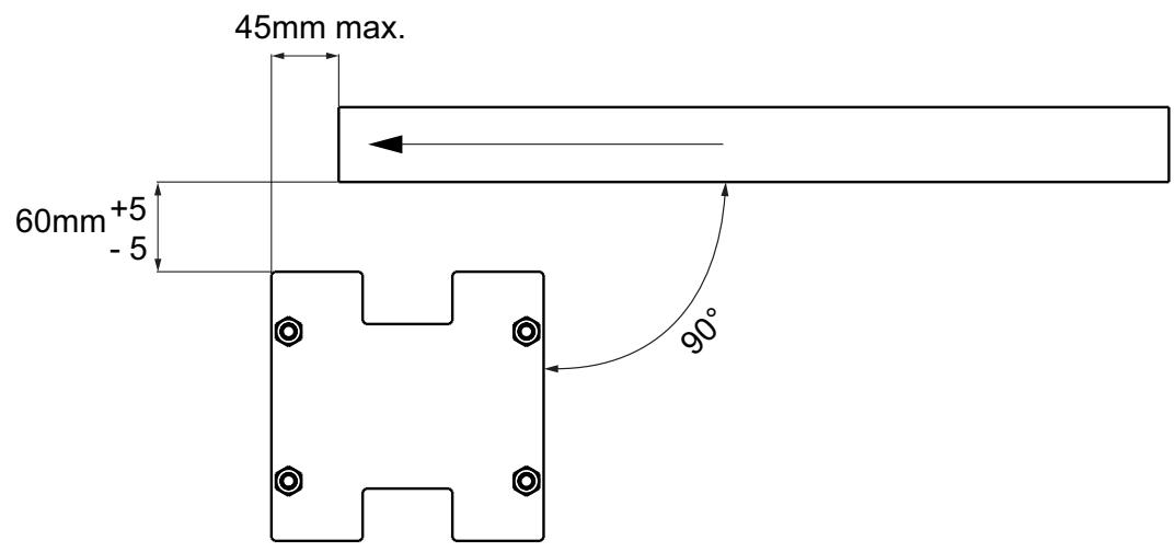
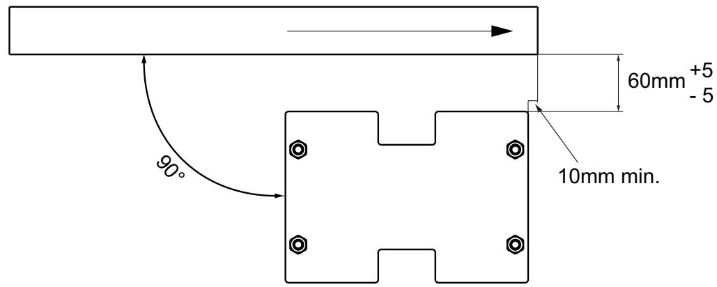
OVERVIEW OF INSTALLATION 5-7+12
The drive has to be installed behind the wall to ensure that no part of it projects out into the gate opening. The motor has to be mounted on the flush fitted base plate. The rack bar shown has to be fitted to the gate with the fixing material supplied.
Decide which is the best height for fixing the rack bar to the gate and use this to determine the installation dimensions for the motor unit and base plate. Should the gate be unsuitable for fitting the rack bar to it, a fixing profile (angle bracket, shaped tubing, etc.) needs to be mounted first.
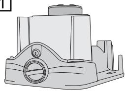
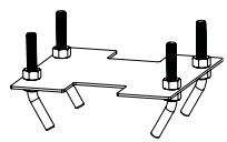
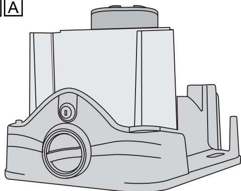
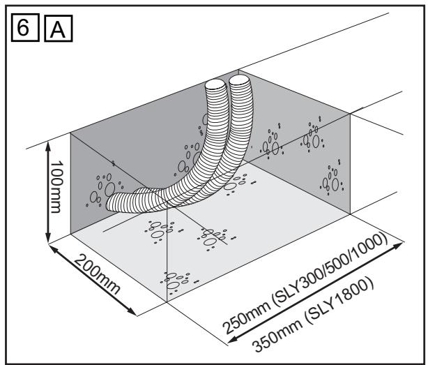
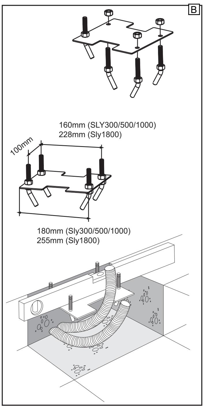
INSTALLATION OF DRIVE BASE PLATE 6 A + B
The base plate for the drive can either be concreted in or, if appropriate, welded into position. The place where the base plate is usually located is shown on the installation overview. The concrete plinth needs to be of an appropriate size (approx. 50cm× 50cm× 50cm ).
Please note: If it is impossible to precisely determine the height of the plinth and the distance from the gate prior to installation, it is advisable to mount the rack bars first and then concrete in the base plate. Spacers are fitted to move the rack bars approx. 40mm towards the inside.
The distance from the bottom edge of the rack bar to the base plate is approx. 8 - 9cm. The base plate permits final height and depth adjustments of several centimetres to be made, but you are advised to work as precisely as possible from the outset.
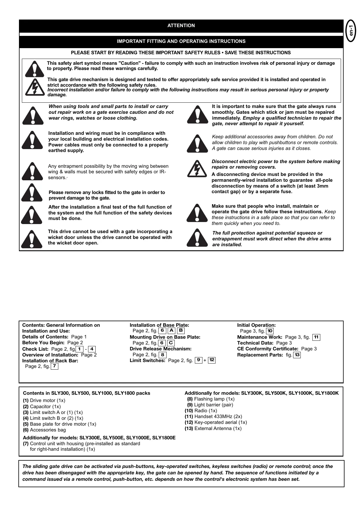
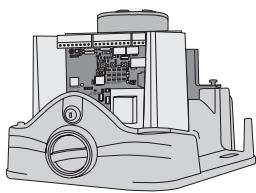
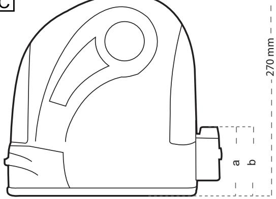
MOUNTING MOTOR AND GEAR UNIT 6 C
The drive should be fitted on to the threaded bolts in the base plate. The height should be set such that there is a gap of approx. 1 - 2mm between the cog wheel and the rack bar. The weight of the gate should not be borne by the cog wheel! Position the drive via the adjustment holes such that its location vis-à-vis the rack bar complies with the installation dimensions.
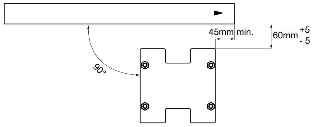
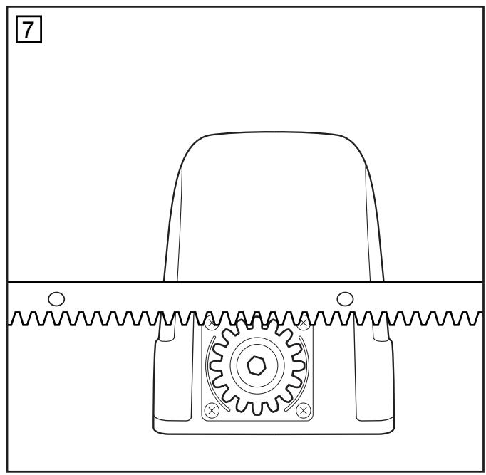
MOUNTING RACK BAR 7
The easiest way to fit the rack bar is to first place it on the motor's drive cog, disengage the motor and, by pushing the gate further with the rack bar, screwing the bar bit by bit firmly in position. In this way, you ensure that the rail bar engages with the cog wheel in an optimum manner. While doing this, do not forget to mark each fixing point.
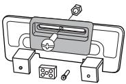
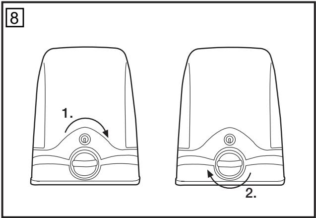
DRIVE RELEASE MECHANISM (MANUAL OPERATION) 8
The drive is equipped with a lockable release mechanism to enable the gate to be operated manually in a power cut. The release mechanism is shown in fig. 8 with the clutch disengaging the link between the cog wheel and the gear.
To release the drive: Position the socket spanner appropriately and turn it 180 degrees. Then turn the release lever 180 degrees too. Finished.
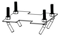
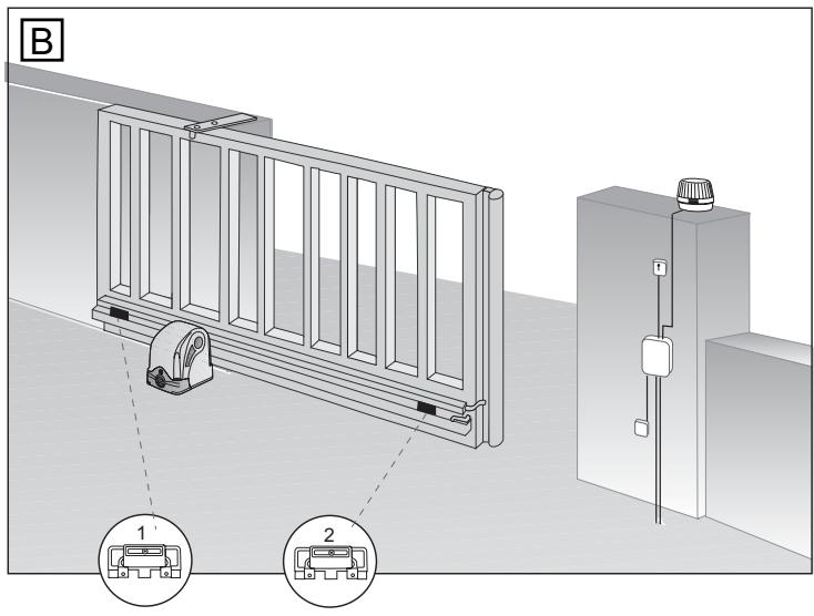
FITTING LIMIT SWITCHES (TO GATE) 9 +12
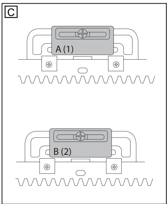
The limit switches are assembled as shown in fig. 9A-C, 12A+B. One limit switch magnet is designated A (1) and the other B (2).
Fit the limit switches on to the rack bar in those places where the final travel positions are roughly expected to be. The magnet should point towards the motor. The switch (contact) is located in the middle of the motor. Screw the retaining clip only provisionally in place or slot it lightly on to the rack bar.
Caution: Please notice fitting of the magnets on the rack bar (fig. 12A+B)
Magnet A (1) = to the left
Magnet B (2) = to the right
Caution: A sliding gate must run in a guide rail and should not be able to leave the rail. This means end stops need to be fitted for both directions!
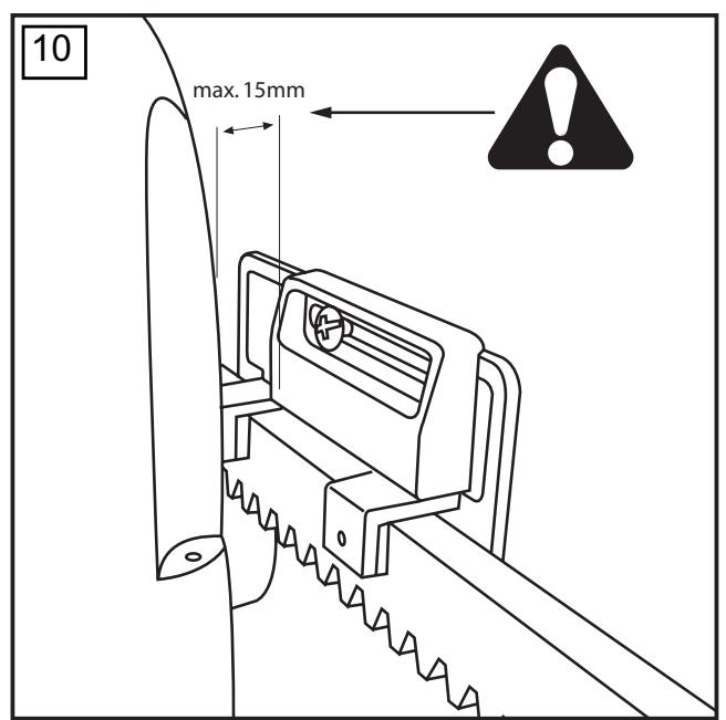
INITIAL OPERATION
Check gate functionality manually when the drive has been disengaged. Electrical operation is only possible with the control unit that is supplied as standard.
Electrical connections: See control unit instructions.
Always ensure that the mechanical and electrical safety requirements relevant to the given system are complied with. fig. 10
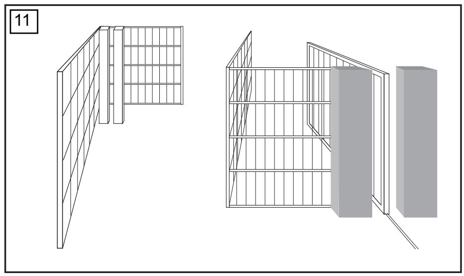
MAINTENANCE WORK
The drive mechanics are maintenance-free. Check at regular intervals (monthly) that the gate hardware and the drive are all firmly in place. Disengage the drive and check gate functionality. Only an easy-running gate will work well with a drive. A drive is no substitute for a poorly functioning gate.
A sliding gate can also be secured by implementing on-site measures (fence, wall, etc.). See fig. 11.
TECHNICAL DATA
| SLY300 | SLY500 | SLY1000 | SLY1800 | |
| Voltage IN | 230Volt | 230Volt | 230Volt | 230Volt |
| Frequency | 50Hz | 50Hz | 50Hz | 50Hz |
| Power | 300W | 360W | 480W | 600W |
| Current rated | 1,3A | 1,5A | 2,1A | 2,6A |
| Torque | 8Nm | 11Nm | 20Nm | 34Nm |
| Capacitor | 8μF | 10μF | 16μF | 20μF |
| Thermal Overload | ||||
| Protection | 140° | 140° | 140° | 140° |
| Motor Speed | 1400 | 1400 | 1400 | 1400 |
| Travel Speed | 10,5 | 10,5 | 10.5 | 8 |
| Duty Cycle | 30 | 30 | 30 | 30 |
| Working Temperature Range | -20°C/+55°C | -20°C/+55°C | -20°C/+55°C | -20°C - 55°C |
| IP44 | IP44 | IP44 | IP44 | |
| Protection Class | I | I | I | I |
| Degree of Protection | 8 | 8 | 10 | 12 |
| Weight approx. Gate Length Max. Gate weight at max. length (incl. 20% reserve) | 5m | 8m | 10m | 12m |
| 300kg | 500kg | 1000kg | 1800kg |
Declaration of Conformity
Automatic Gate Opener Models SLY300/E/K, SLY500/E/K, SLY1000/E/K, SLY1800/E/K
Series are in conformity to the applicable
sections of StandardsEN300220-3 • EN55014 • EN61000-3 • EN60555, EN60335-1 • ETS
300 683·EN60335-1:2002·EN60335-2-103:2003·EN55014-1:2000 +A1 +A2
EN55014-2: 2001 • EN61000-3-2: 2000 • EN61000-3-3: 1995 + A1 • EN 301 489-3,
V1.3.1·EN 300 220-3 V1.1.1·EN13241-1
per the provisions & all amendments
of the EU Directives 2006/95/EC, 2004/108/EC, 1999/5/EG
Declaration of Incorporation
Automatic Gate Opener Models, when installed and maintained according to all the Manufacturer's instructions in combination with a Gate, which has also been installed and maintained according to all the Manufacturer's instructions, meets the provisions of EU Directive 89/392/EEC and all amendments.
I , the undersigned, hereby declare that the equipment specified above and any accessory listed in the manual conforms to the above Directives and Standards.
B.P.Kelkhoff
Manager, Regulatory Affairs
Chamberlain GmbH
D-66793 Saarwellingen
January, 2009

Dabbaia P. Keckhoft
IMPORTANT ISTRUZIONI PER IL MONTAGGIO E L'USO
PER PRIMA COSA LEGGERE QUESTE IMPORTANTI NORME DI SICUREZZA!


Inoltre, per i modelli: SLY300E, SLY500E, SLY1000E, SLY1800E
Manager, Regulatory Affairs
Chamberlain GmbH
D-66793 Saarwellingen
January, 2009

BaBaa P. KeckhoH
BELANGRIJKE INSTRUCTIES VOOR MONTAGE EN GEBRUIK
BEGIN MET HET LEZEN VAN DEZE BELANGRIJKE VEILIGHEIDSINSTRUCTIES!


The easiest way to fit the rack bar is to first place it on the motor's drive cog, disengage the motor and, by pushing the gate further with the rack bar, screwing the bar bit by bit firmly in position. In this way, you ensure that the rail bar engages with the cog wheel in an optimum manner. While doing this, do not forget to mark each fixing point.
AANDRIJVING ONTGRENDELEN (HANDBEDIENING) 8
Magneet A (1) = links
Navfc k modelum: SLY300E, SLY500E, SLY1000E, SLY1800E
2006/95/EC, 2004/108/EC, 1999/5/EG
Zavrečné prohlášení
B.P.Kelkhoff
Manager, Regulatory Affairs
Chamberlain GmbH
D-66793 Saarwellingen
January, 2009

Dabbaia P. KeckhoH
Manager, Regulatory Affairs
Chamberlain GmbH
D-66793 Saarwellingen
January, 2009

Babaa P. KeckhoH
FONTOS TUDNIVALOK A SZERELESHEZ E5 A HASZNALATHOZ
KEZDJE EZEN FONTOS BIZTONSÁGÍ SZABÁLYOK OLVASÁSÁVAL.

Manager, Regulatory Affairs
Chamberlain GmbH
D-66793 Saarwellingen
January, 2009

Barbala P. KeckhoH
VAZEN UPUTE ZA MONTAZU I KORISTENJE
ZAPOCNITE S CITANJEM OVIH VAZNIH SIGURNOSNIH UPUTA

Ovi simboli upozorenja označavaju rijec "Pažnja!", poziv za obracanje pažnje, jer njihovo nepostivanje moze prouzrokovati ostećenje ljudskog zdravlja ili materijalnu štetu. Molimo da pročitate ova upozorenja pažljivo.
Ovaj pogonski mehanizam za kapiju konstruiran je i testiran takdo prilikom instalacije i upotrebe uz tocno poštivanje pravila bezbjednosti osigurava primjerenu bezbjednost.
.2006/95/EC, 2004/108/EC, 1999/5/EG
Manager, Regulatory Affairs
Chamberlain GmbH
D-66793 Saarwellingen
January, 2009

Dabbaa P. Keckho
WAZNE WSKAZOWKI DOTYCZE MONTAZI WYKORZYSTANIA
NA POCZATEK NALEZY ZAPOZNAÇ SIE Z NINIEJSZYMI WAZNYMI ZASADAMI BEZPIECZEÑSTWA

Dodatkowo dla modeli: SLY300E, SLY500E, SLY1000E, SLY1800E
INFORMACJE POCZATKOWE
1.2006/95/EC, 2004/108/EC, 1999/5/WE
B.P.Kelkhoff
Manager, Regulatory Affairs Chamberlain GmbH
D-66793 Saarwellingen
January, 2009

Babaa P. Keckhoft
BAXHbIe YKA3AHnI PO MOHTAXU IcNoJIb3OBAHnIO
HACHNTE C IPOUTEHIN 3TINX BAXKbIX IPIPABNJ TEXHNI K E3OJNACHOCTN


3Tn npEynpexkaioune cHMBOJI b O3HaayoT "BHHMaHne", oBaueHne K BaWemy BHHMaHNo, taK kaN Hec6bIeHne MorJIO 6bl npuHNHT bpe 3dOpOBbIy YelOBeka nII MaTePnaIbHbI yIep6.
Ioxaynyucta, BHMaTeNbHO npOHTaTE 3TN npEynpeXeHn.
063op MoHTaxKa: cTp.2
MOnTaX 3y6aToN peKn: cTp.2,pnc
Texo6cIyKuBaHne: cTp. 3, pnc.11
exHnueckne xapaKTepeuCTnKn: cTp.3
CepTHΦHKAT COOTBETCTBnH HOpMaM EC: cTp.3
3anactn: pnc. 13
Copejxmoe npka c SLY300, SLY500, SLY1000, SLY1800
(1) MoToP npNbOda (1x)
(2) KoHdEHCaTOP (1x)
(3) KoHeuHbIy BbIKHIOUaTeJIb A uJIn (1) (1x)
(4) KoheuHbI BvIKNoUaTeIb B nII (2) (1x)
(5)Плпта ochobань моторapnpвда (1x)
(6)Пакет с пинадлесховсмN
Дононтелбно Дд моделен: SLY300E, SLY500E, SLY1000E, SLY1800E
BHMaHHe! O6paaMaTe BHMaHHe Ha MOHTaX MaHHTOB Ha 3y6CuToi peKe (12A+B).
MarHnT A (1) = cIeBa;
MarHnT B (2) = cnpaba;
BHMaHHe:Pa3dBnXHbIe BOPoTa DOnJXHbI nepeMeaTbcra B BbIHyKdEHHom peXHMe, T.e. He MoKeTe 6bITb TaK, YTO6bI BOPoTa CXOJIIN C HAnpaBnAIOxN. PpN DnIXKeHN BOPOT B O6Ox HApBaJIeHNrX DoJXHbI 6bITb PpeDyCMOTpeHbI orpaHnHTeIN XoJa.
NEPBOE BKJIIOUeyHne
yDObBnTbOpAOT TpeoBaHnAM DeIcTByUOux
pa3dienob ctaandaptoB EN300220-3, EN55014, EN61000, EN61000-3, EN60555,
EN60335-1, ETS 300 683, EN60335-1:2002, EN60335-2-103:2003, EN55014-1:
2000+A1+A2, EN55014-2:2001, EN61000-3-2:2000, EN61000-3-3:1995+A1, EN
301 489-3. V1.3.1, EN 300 220-3 V1.1.1, EN 13241-1,
a TaKke onpeIeHn n dpyrnx doonHeHn dinpeKtNB EC. 2006/95/EC,
2004/108/EC, 1999/5/EG
3aBHeHne O BkJIIOueHn
ABMATMUCHEK pnpBOBbI BOPT YOBDNTBOPHOT ONOpEJIeHNmI DApEKTMBE BC 89/393/EEC IN eD OONHOENHM PnIYOCNBI, ECIN3 TnP INPOBDbI yCTAHOBIEHn I O6CNyXHBaOTcC C o6NIODeHMe HmHCTpykUIM N3ROBOTeTHe I MTONIOyOTcC A BOPOTAM, KOTOpBE TAKXE yCTAHOBIEHbI N O6CNyXHBaOTcB C COOTBTCTBMn C hNtCPYKUNI N3ROBOTeTHe.
HactoHm HxKeOnnncBnnc 3aABnE, YTO BbiyeNOMaHyTOE yCTPOIcTBO, a
TaKKe BCE npNBeDeHHbIe B pyKOBoDCTBe npHaJNeXHOCTN, COOTBETCTBYOT
BbIWeHa3BaHHbIM DnpeKTHBAM N CTaHdapTaM.
B.P.Kelkhoff
Manager, Regulatory Affairs
Chamberlain GmbH
D-66793 Saarwellingen
January, 2009

Baalbala P. KeckhoH
1
SLY300/500/1000/1800


2
SLY300E/500E/1000E/1800E


3
SLY300K/500K/1000K/1800K


4


5A

B
C
$$ \begin{array}{l} a = 8 6 m m S l y 3 0 0 / 5 0 0 / 1 0 0 0 \ b = 7 8 m m S L Y 1 8 0 0 \ \end{array} $$

SLY300/500/1000
SLY1800
80mm max.


0


NOTES: