PST 18 LI - Jigsaw BOSCH - Free user manual and instructions
Find the device manual for free PST 18 LI BOSCH in PDF.
| Product type | Cordless jigsaw |
| Brand | BOSCH |
| Model | PST 18 LI |
| Nominal voltage | 18 V |
| Power type | Lithium-Ion battery (not included) |
| Variable no-load speed | 0 - 2400 strokes/min |
| Stroke length | 20 mm |
| Max cutting depth in wood | 80 mm |
| Max cutting depth in aluminum | 12 mm |
| Max cutting depth in steel | 5 mm |
| Bevel cut angle | 45° (left or right) |
| Pendulum action | 4 adjustable positions (no pendulum to strong pendulum) |
| Weight (according to EPTA 01/2003) | 1.9 kg |
| Work light | LED Power Light |
| Plunge cut | Yes (wood, plasterboard) |
| Parallel guide with circular cutting device | Accessory available |
| Cut Control trace control | Optional (with indicator light and base) |
| Electronic Cell Protection (ECP) | Yes (against deep discharge) |
| Battery charge indicator | 3 green LEDs |
| Blade change system | SDS (tool-free) |
| Blade shank type | T-shank (1/4" universal) |
| Dust extraction cover | Yes (for vacuum connection) |
| Roller blade guide | Removable (periodic lubrication required) |
| Maintenance | Regularly clean ventilation slots and blade holder |
| Battery charging temperature | 0 °C to 45 °C |
Frequently Asked Questions - PST 18 LI BOSCH
User questions about PST 18 LI BOSCH
0 question about this device. Answer the ones you know or ask your own.
Ask a new question about this device
Download the instructions for your Jigsaw in PDF format for free! Find your manual PST 18 LI - BOSCH and take your electronic device back in hand. On this page are published all the documents necessary for the use of your device. PST 18 LI by BOSCH.
USER MANUAL PST 18 LI BOSCH
Power Tools Division
70745 Leinfelden-Echterdingen
Germany
www.bosch-pt.com
2609004236(2010.05)O/160WEU

2609004236
PST 18 LI

BOSCH
de Originalbetriebsanleitung
el Ipiototuno odyiwxphonc
en Original instructions
tr Original isletme talimati
fr Notice originale
ar
es Manual original
pt Manual original
it Istruzioni originali
nI Oorspronkelijke
gebruksaanwijzing
da Original brugsanvisning
sv Bruksanvisning i original
no Original driftsinstruks
fi Alkuperäiset ohjeet

Deutsch. 7
English. Page 19
Francais.. Page 30
Espanol . Pagina 42
Portugués Pagina 54
Italiano 65
Nederlands. 77
Dansk . 88
Svenska. 98
Norsk. Side 108
Suomi . 117
Elambdavika 27
Türkce Sayfa 139
157
Bosch Power Tools
2609004236| (5.5.10)


4
2609004236|(5.5.10)
Bosch Power Tools
6
Sicherheitshinweise
Dr. Egbert Schneider
Dr. Eckerhard Strötgen
Senior Vice President
Head of Product
Engineering
Certification
ppa. Maee i.v. Nooey
Robert Bosch GmbH, Power Tools Division
D-70745 Leinfelden-Echterdingen
07.04.2010
12 | Deutsch
Montage
General Power Tool SafetyWarnings
WARNING
Read all safety warnings and all instructions. Failure to follow
the warnings and instructions may result in electric shock, fire and/or serious injury.
Save all warnings and instructions for future reference.
The term "power tool" in the warnings refers to your mains-operated (corded) power tool or battery-operated (cordless) power tool.
1) Work area safety
a) Keep work area clean and well lit. Cluttered or dark areas invite accidents.
b) Do not operate power tools in explosive atmospheres, such as in the presence of flammable liquids, gases or dust. Power tools create sparks which may ignite the dust or fumes.
c) Keep children and bystanders away while operating a power tool. Distractions can cause you to lose control.
2) Electrical safety
a) Power tool plugs must match the outlet. Never modify the plug in any way. Do not use any adapter plugs with earthed (grounded) power tools. Unmodified plugs and matching outlets will reduce risk of electric shock.
b) Avoid body contact with earthed or grounded surfaces, such as pipes, radiators, ranges and refrigerators. There is an increased risk of electric shock if your body is earthed or grounded.
c) Do not expose power tools to rain or wet conditions. Water entering a power tool will increase the risk of electric shock.
d) Do not abuse the cord. Never use the cord for carrying, pulling or unplugging the power tool. Keep cord away from heat, oil, sharp edges and moving parts. Damaged or entangled cords increase the risk of electric shock.
e) When operating a power tool outdoors, use an extension cord suitable for outdoor use. Use of a cord suitable for outdoor use reduces the risk of electric shock.
f) If operating a power tool in a damp location is unavoidable, use a residual current device (RCD) protected supply. Use of an RCD reduces the risk of electric shock.
3) Personal safety
a) Stay alert, watch what you are doing and use common sense when operating a power tool. Do not use a power tool while you are tired or under the influence of drugs, alcohol or medication. A moment of inattention while operating power tools may result in serious personal injury.
b) Use personal protective equipment. Always wear eye protection. Protective equipment such as dust mask, non-skid safety shoes, hard hat, or hearing protection used for appropriate conditions will reduce personal injuries.
c) Prevent unintentional starting. Ensure the switch is in the off-position before connecting to power source and/or battery pack, picking up or carrying the tool. Carrying power tools with your finger on the switch or energising power tools that have the switch on invites accidents.
d) Remove any adjusting key or wrench before turning the power tool on. A wrench or a key left attached to a rotating part of the power tool may result in personal injury.
e) Do not overreach. Keep proper footing and balance at all times. This enables better control of the power tool in unexpected situations.
f) Dress properly. Do not wear loose clothing or jewellery. Keep your hair, clothing and gloves away from moving parts. Loose clothes, jewellery or long hair can be caught in moving parts.

20 | English
g) If devices are provided for the connection of dust extraction and collection facilities, ensure these are connected and properly used. Use of dust collection can reduce dust-related hazards.
4) Power tool use and care
a) Do not force the power tool. Use the correct power tool for your application. The correct power tool will do the job better and safer at the rate for which it was designed.
b) Do not use the power tool if the switch does not turn it on and off. Any power tool that cannot be controlled with the switch is dangerous and must be re-paired.
c) Disconnect the plug from the power source and/or the battery pack from the power tool before making any adjustments, changing accessories, or storing power tools. Such preventive safety measures reduce the risk of starting the power tool accidentally.
d) Store idle power tools out of the reach of children and do not allow persons unfamiliar with the power tool or these instructions to operate the power tool. Power tools are dangerous in the hands of untrained users.
e) Maintain power tools. Check for misalignment or binding of moving parts, breakage of parts and any other condition that may affect the power tool's operation. If damaged, have the power tool repaired before use. Many accidents are caused by poorly maintained power tools.
f) Keep cutting tools sharp and clean. Properly maintained cutting tools with sharp cutting edges are less likely to bind and are easier to control.
g) Use the power tool, accessories and tool bits etc. in accordance with these instructions, taking into account the working conditions and the work to be performed. Use of the power tool for operations different from those intended could result in a hazardous situation.
5) Battery tool use and care
a) Recharge only with the charger specified by the manufacturer. A charger that is suitable for one type of battery pack may create a risk of fire when used with another battery pack.
b) Use power tools only with specifically designated battery packs. Use of any other battery packs may create a risk of injury and fire.
c) When battery pack is not in use, keep it away from other metal objects, like paper clips, coins, keys, nails, screws or other small metal objects, that can make a connection from one terminal to another. Shorting the battery terminals together may cause burns or a fire.
d) Under abusive conditions, liquid may be ejected from the battery; avoid contact. If contact accidentally occurs, flush with water. If liquid contacts eyes, additionally seek medical help. Liquid ejected from the battery may cause irritation or burns.
6) Service
a) Have your power tool serviced by a qualified repair person using only identical replacement parts. This will ensure that the safety of the power tool is maintained.
SafetyWarnings for Jigsaws
- Hold power tool by insulated gripping surfaces, when performing an operation where the cutting accessory may contact hidden wiring. Cutting accessory contacting a "live" wire may make exposed metal parts of the power tool "live" and could give the operator an electric shock.
- Keep hands away from the sawing range. Do not reach under the workpiece. Contact with the saw blade can lead to injuries.
- Apply the machine to the workpiece only when switched on. Otherwise there is danger of kickback when the cutting tool jams in the workpiece.
English | 21
Pay attention that the base plate 9 rests securely on the material while sawing. A jammed saw blade can break or lead to kickback.
When the cut is completed, switch off the machine and then pull the saw blade out of the cut only after it has come to a standstill. In this manner you can avoid kickback and can place down the machine securely.
Use only sharp, flawless saw blades. Bent or unsharp saw blades can break or cause kickback.
Do not brake the saw blade to a stop by applying side pressure after switching off. The saw blade can be damaged, break or cause kickback.
- Use appropriate detectors to determine if utility lines are hidden in the work area or call the local utility company for assistance. Contact with electric lines can lead to fire and electric shock. Damaging a gas line can lead to explosion. Penetrating a water line causes property damage or may cause an electric shock.
- Secure the workpiece. A workpiece clamped with clamping devices or in a vice is held more secure than by hand.
- Keep your workplace clean. Blends of materials are particularly dangerous. Dust from light alloys can burn or explode.
Always wait until the machine has come to a complete stop before placing it down. The tool insert can jam and lead to loss of control over the power tool.
Do not open the battery. Danger of short-circuiting.

Protect the battery against heat, e. g., against continuous intense sunlight, fire, water, and moisture. Danger of explosion.
In case of damage and improper use of the battery, vapours may be emitted. Provide for fresh air and seek medical help in case of complaints. The vapours can irritate the respiratory system.
- Use the battery only in conjunction with your Bosch power tool. This measure alone protects the battery against dangerous overload.
- Use only original Bosch batteries with the voltage listed on the nameplate of your power tool. When using other batteries, e. g. imitations, reconditioned batteries or other brands, there is danger of injury as well as property damage through exploding batteries.
Functional Description

Read all safety warnings and all instructions. Failure to follow the warnings and instructions may result in electric shock, fire and/or serious injury.
Intended Use
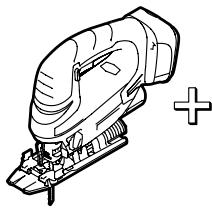
The machine is intended for making separating cuts and cut-outs in wood, plastic, metal, ceramic plates and rubber while resting firmly on the workpiece. It is suitable for straight and curved cuts with metre angles to 45^ . The saw blade recommendations are to be observed.
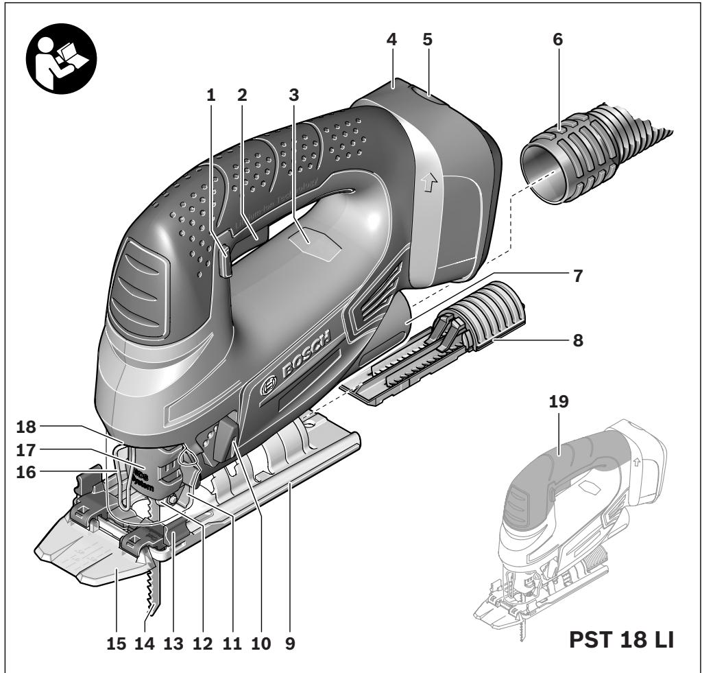
Product Features
The numbering of the product features refers to the illustration of the machine on the graphics page.
1 Lock-off button for On/Off switch
2 On/Off switch
3 Battery charge-control indicator
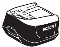
4 Battery
5 Battery unlocking button
6 Vacuum hose
7 Vacuum connection
8 Saw blade storage
9 Base plate
10 Adjusting lever for orbital action
11 Dust cover for vacuuming
12 Guide roller

22 | English
13 "Cut Control" base
14 Saw blade
15 "Cut Control" viewing window
16 Contact protector
17 Saw blade holder
18 "PowerLight"
19 Handle (insulated gripping surface)
20 Splinter guard
21 Lead for the parallel guide
22 Scale for metre angle
23 Screw
24 Cutting mark, 0^
25 Cutting mark, 45^
26 Locking screw for parallel guide
27 Parallel guide with circle cutter
28 Centring tip of the parallel guide
*Accessories shown or described are not part of the standard delivery scope of the product. A complete overview of accessories can be found in our accessories program.
Technical Data
| Jigsaw | PST 18 LI | |
| Article number | 3603 K11 0.. | |
| Rated voltage | V= | 18 |
| Stroke rate control | ● | |
| Orbital action | ● | |
| Stroke rate at no load n0 | min-1 | 0-2400 |
| Stroke | mm | 20 |
| Cutting capacity, max. | ||
| - in wood | mm | 80 |
| - in aluminium | mm | 12 |
| - in non-alloy steel | mm | 5 |
| Bevel cuts (left/right), max. | ° | 45 |
| Weight according to EPTA-Procedure 01/2003 | kg | 1.9 |
| Please observe the article number on the type plate of your machine. The trade names of the individual machines may vary. | ||
Noise/Vibration Information
Measured sound values determined according to EN 60745.
Typically the A-weighted noise levels of the product are: Sound pressure level 81 dB(A); Sound power level 92 dB(A). Uncertainty K = 3 dB.
Wear hearing protection!
Vibration total values (triax vector sum) determined according to EN 60745:
Cutting board: Vibration emission value a_h = 8 m/s^2 , Uncertainty K = 1.5 m/s^2
Cutting sheet metal: Vibration emission value a_h = 5 m/s^2 , Uncertainty K = 1.5 m/s^2 .
The vibration emission level given in this information sheet has been measured in accordance with a standardised test given in EN 60745 and may be used to compare one tool with another. It may be used for a preliminary assessment of exposure.
The declared vibration emission level represents the main applications of the tool. However if the tool is used for different applications, with different accessories or poorly maintained, the vibration emission may differ. This may significantly increase the exposure level over the total working period.
An estimation of the level of exposure to vibration should also take into account the times when the tool is switched off or when it is running but not actually doing the job. This may significantly reduce the exposure level over the total working period.
Identify additional safety measures to protect the operator from the effects of vibration such as: maintain the tool and the accessories, keep the hands warm, organisation of work patterns.
Declaration of Conformity C
We declare under our sole responsibility that the product described under "Technical Data" is in conformity with the following standards or standardization documents: EN 60745 according to the provisions of the directives 2004/108/EC, 2006/42/EC.

English | 23
Technical file at:
Robert Bosch GmbH, PT/ESC,
D-70745 Leinfelden-Echterdingen
Dr. Egbert Schneider
Senior Vice President
Engineering
Dr. Eckerhard Strötgen
Head of Product
Certification

Robert Bosch GmbH, Power Tools Division
D-70745 Leinfelden-Echterdingen
07.04.2010
Assembly
Before any work on the machine itself (e.g. maintenance, tool change, etc.) as well as during transport and storage, remove the battery from the power tool. There is danger of injury when unintentionally actuating the On/Off switch.
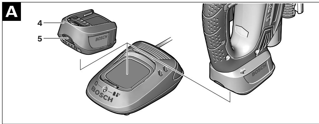
Battery Charging (see figure A)
- Use only the battery chargers listed on the accessories page. Only these battery chargers are matched to the lithium ion battery of your power tool.
Note: The battery is supplied partially charged. To ensure full capacity of the battery, completely charge the battery in the battery charger before using your power tool for the first time.
The lithium ion battery can be charged at any time without reducing its service life. Interrupting the charging procedure does not damage the battery.
The lithium ion battery is protected against deep discharging by the "Electronic Cell Protection (ECP)". When the battery is empty, the machine is switched off by means of a protective circuit: The inserted tool no longer rotates.
WARNING
Do not continue to press the On/Off switch after the ma
chine has been automatically switched off. The battery can be damaged.
To remove the battery 4, press the battery unlocking button 5 and pull the battery upward out of the power tool. Do not exert any force.
The battery is equipped with a NTC temperature control which allows charging only within a temperature range of between 0^ and 45^ . A long battery service life is achieved in this manner.
Observe the notes for disposal.
Replacing/Inserting the Saw Blade
- When mounting the saw blade, wear protective gloves. Danger of injury when touching the saw blade.
Selecting a Saw Blade
An overview of recommended saw blades can be found at the end of these instructions. Use only T-shank saw blades or saw blades with 1/4'' universal shank (U-shank). The saw blade should not be longer than required for the intended cut.
Use a thin saw blade for narrow curve cuts.
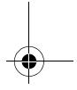
Inserting the Saw Blade (see figure B)
- Clean the shank of the saw blade before inserting it. An unclean shank cannot be fastened securely.
If required, remove the dust cover 11 (see "Dust Cover").
Push the saw blade holder 17 upward in the direction of the arrow. Insert the saw blade 14 (teeth in cutting direction) to the stop into the saw blade holder.
While inserting the saw blade, pay attention that the back of the saw blade is positioned in the groove of the guide roller 12.
Check the tight seating of the saw blade. A loose saw blade can fall out and lead to injuries.
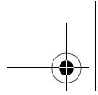
Removing the Saw Blade (see figure C)
Push the saw blade holder 17 upward in the direction of the arrow and remove the saw blade 14.
24 | English
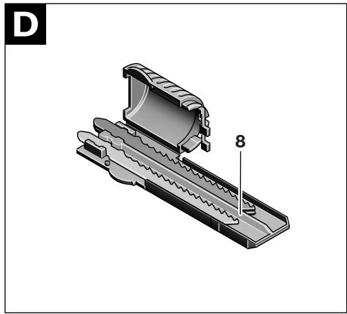
Saw Blade Storage (see figure D)
Up to six saw blades with lengths to 110~mm can be stored in the saw blade storage 8. Insert the saw blades with the T-shank into the recess of the saw blade storage intended for this. Up to three saw blades can be placed on top of each other.
Shut the saw blade storage and slide it to the stop into the opening of the base plate 9.
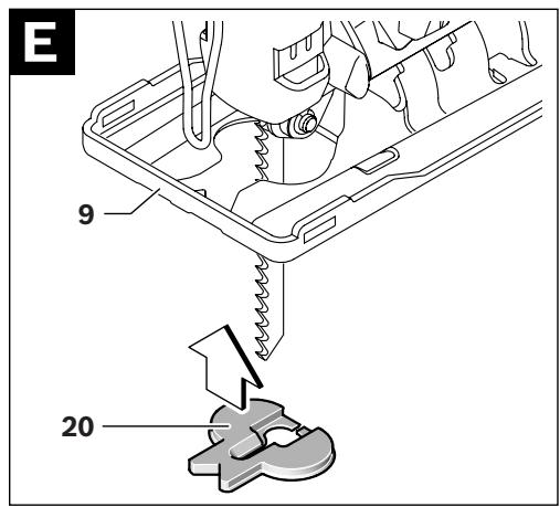
Splinter Guard (see figure E)
The splinter guard 20 (accessory) can prevent fraying of the surface while sawing wood. The splinter guard can only be used for certain saw blade types and only for cutting angles of 0^ . When sawing with the splinter guard, the base plate 9 must not be moved back for cuts that are close to the edge.
Press the splinter guard 20 from below into the base plate 9 (with the notch facing upward as shown in the figure).
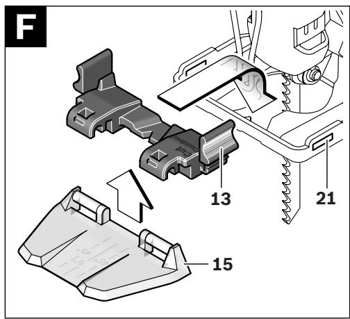
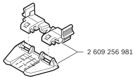
"Cut Control"
"Cut Control" enables precise guiding of the power tool along a cutting line marked on the workpiece. The "Cut Control" kit includes the viewing window 15 with cutting marks and the base 13 for attachment to the power tool.
Attaching "Cut Control" to the Base Plate (see figure F)
Clamp the "Cut Control" 15 viewing window into the holders of the base 13. Then, lightly press the base together and allow it to engage into the lead 21 of the base plate 9.
Dust/Chip Extraction
Dusts from materials such as lead-containing coatings, some wood types, minerals and metal can be harmful to one's health. Touching or breathing-in the dusts can cause allergic reactions and/or lead to respiratory infections of the user or bystanders.
Certain dusts, such as oak or beech dust, are considered as carcinogenic, especially in connection with wood-treatment additives (chromate, wood preservative). Materials containing asbestos may only be worked by specialists.
- Use dust extraction whenever possible.
- Provide for good ventilation of the working place.
- It is recommended to wear a P2 filter-class respirator.
Observe the relevant regulations in your country for the materials to be worked.
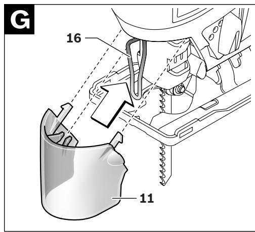
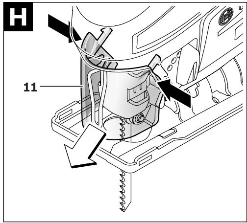
Dust Cover (see figures G-H)
Mount the dust cover 11 before connecting the machine to the dust extraction.
Mount the dust cover 11 onto the machine in such a manner that the centre holder engages on the contact protector 16 and the two outer holders engage in the openings on the casing.
Remove the dust cover 11 for applications without dust extraction as well as when performing litre cuts. For this, push the dust cover together at the two outer holders and pull it off toward the front.
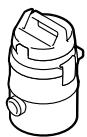
Connecting the Dust Extraction
Place a vacuum hose 6 (accessory) onto the vacuum connection 7. Connect the vacuum hose 6 with a vacuum cleaner (accessory). An overview for the connection of various vacuum cleaners can be found at the end of these instructions.
To enable optimum dust extraction, use the splinter guard 20 if possible.
The vacuum cleaner must be suitable for the material being worked.
When vacuuming dry dust that is especially detrimental to health or carcinogenic, use a special vacuum cleaner.
Operation
Operating Modes
Before any work on the machine itself (e.g. maintenance, tool change, etc.) as well as during transport and storage, remove the battery from the power tool. There is danger of injury when unintentionally actuating the On/Off switch.
Orbital Action Settings
The four orbital action settings allow for optimal adaptation of cutting speed, cutting capacity and cutting pattern to the material being sawed.
The orbital action can be adjusted with the adjusting lever 10, even during operation.

No orbital action
Small orbital action
Medium orbital action
Large orbital action
The optimal orbital action setting for the respective application can be determined through practical testing. The following recommendations apply:
- Select a lower orbital action setting (or switch it off) for a finer and cleaner cutting edge.
- For thin materials such as sheet metal, switch the orbital action off.
- For hard materials such as steel, work with low orbital action.
- For soft materials and when sawing in the direction of the grain, work with maximum orbital action.
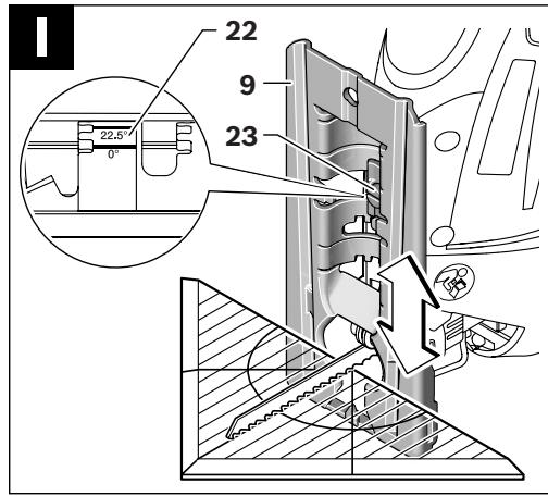
Adjusting the Cutting Angle (see figure 1)
The base plate 9 can be swivelled by 45^ to the left or right for litre cuts.
- Remove the dust cover 11 and the vacuum connection 7.
- Pull the saw blade storage 8 out of the base plate 9.
- Loosen the screw 23 and lightly slide the base plate 9 toward the vacuum connection 7.
- For adjustment of precise metre angles, the base plate has adjustment notches on the left and right at 0^ , 22.5^ and 45^ . Swivel the base plate 9 to the desired position according to the scale 22. Other metre angles can be adjusted using a protractor.
- Afterwards, push the base plate 9 to the stop in the direction of the saw blade 14.
- Tighten the screw 23 again.
The dust cover 11, vacuum connection 7 and splinter guard 20 cannot be used for litre cuts.
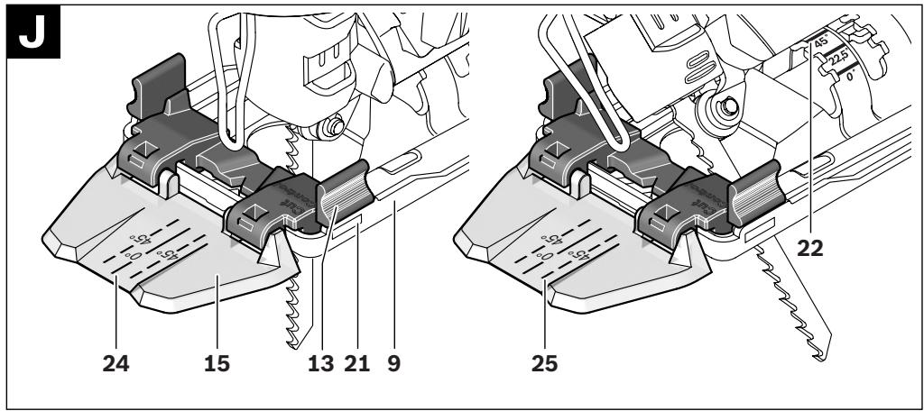
Cut Control for Bevel Cuts (see figure J)
For cutting-line control of bevel cuts, the "Cut Control" viewing window 15 has a mark 24 for 0^ right-angle cuts and a mark 25 each for the left- or rightward sloping 45^ bevel cut according to scale 22.
The cutting mark for bevel cuts between 0^ and 45^ results proportionally. It can additionally be drawn on the "Cut Control" viewing window 15 with a non-permanent marker, and easily be removed again.
For accurate working, it is best to carry out a test cut.
Offsetting the Base Plate (see figure 1)
For sawing close to edges, the base plate 9 can be offset to the rear.
Loosen the screw 23 and slide the base plate 9 toward the vacuum connection 7 to the stop.
Tighten the screw 23 again.
Sawing with the base plate 9 offset is possible only at a 0^ bevel angle. Additionally, "Cut Control" may not be used together with the base 13, the parallel guide with circle cutter 27 (accessory), as well as the splinter guard 20.
Starting Operation
Inserting the Battery
- Use only original Bosch lithium ion batteries with the voltage listed on the nameplate of your power tool. Using other batteries can lead to injuries and pose a fire hazard.
Switching On and Off
To start the machine, first push the lock-off button for the On/Off switch 1 and then press the On/Off switch 2 and keep it pressed.
The power light 18 lights up when the On/Off switch 2 is slightly or completely pressed, and allows the work area to be illuminated when lighting conditions are insufficient.
To switch off the machine, release the On/Off switch 2.
Note: For safety reasons, the On/Off switch 2 cannot be locked; it must remain pressed during the entire operation.

26 | English
Controlling the Stroke Rate
Increasing or reducing the pressure on the On/Off switch 2 enables stepless stroke-rate control of the switched-on machine.
Light pressure on the On/Off switch 2 results in a low stroke rate. Increasing the pressure also increases the stroke rate.
The required stroke rate is dependent on the material and the working conditions and can be determined by a practical trial.
Reducing the stroke rate is recommended when the saw blade engages in the material as well as when sawing plastic and aluminium.
After longer periods of work at low stroke rate, the machine can heat up considerably. Remove the saw blade from the machine and allow the machine to cool down by running it for approx. 3 minutes at maximum stroke rate.
Battery Charge-control Indication
The battery charge-control indicator 3 indicates the charge condition of the battery when the machine is switched on. It consists of 3 green LEDs.
| LED | Capacity |
| Continuous lighting 3 x green | ≥ 66% |
| Continuous lighting 2 x green | 34–65% |
| Continuous lighting 1 x green | 11–33% |
| Slow flashing 1 x green | ≤ 10% |
Temperature Dependent Overload Protection
When using the machine as intended for, it cannot be subject to overload. In case of excessive load or when not within the permitted battery temperature range of 0 - 70^ , the speed is reduced or the machine switches off. With reduced speed, the machine will not run at full speed again until after reaching the permitted battery temperature or when the load is reduced. In case of automatic shut-off, switch the machine off, allow the battery to cool down and then switch the machine on again.
The 3 LEDs of the battery charge-control indicator 3 flash rapidly when the battery temperature is not within the operating temperature range of -30 to +65^ , and/or when the overload protection has responded.
Protection Against Deep Discharging
The lithium ion battery is protected against deep discharging by the "Electronic Cell Protection (ECP)". When the battery is empty, the machine is switched off by means of a protective circuit: The inserted tool no longer rotates.
Working Advice
- When working small or thin workpieces, always use a stable support or a saw station (Bosch PLS 300).
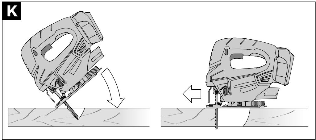
Plunge Cutting (see figure K)
- Plunge cuts may only be applied to soft materials, such as wood, gypsum plaster boards, etc.!.
Use only short saw blades for plunge cutting. Plunge cutting is possible only with the litre angle set at 0^ .
Place the machine with the front edge of the base plate 9 on to the workpiece without the saw blade 14 touching the workpiece and switch on. For machines with stroke rate control, select the maximum stroke rate. Firmly hold the machine against the workpiece and by tilting the machine, slowly plunge the saw blade into the workpiece.
When the base plate 9 fully lays on the workpiece, continue sawing along the desired cutting line.
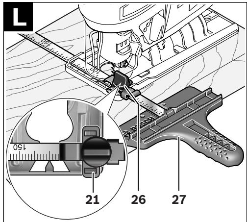
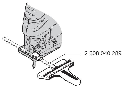
Parallel Guide with Circle Cutter (Accessory)
For cuts using the parallel guide with circle cutter 27 (accessory), the thickness of the material must not exceed a maximum of 30~mm .
Remove the "Cut Control" base 13 from base plate 9. For this, lightly press the base together and remove it from the guide 21.
English | 27
Parallel Cuts (see figure L): Loosen the locking screw 26 and slide the scale of the parallel guide through the lead 21 in the base plate. Set the desired cutting width as the scale value on the inside edge of the base plate. Tighten the locking screw 26.
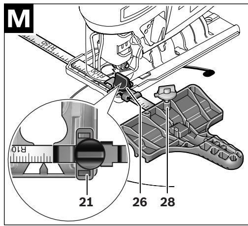
Circular Cuts (see figure M): Drill a hole (large enough to accommodate the saw blade) close to the cutting line within the circle to be sawn. Work the drill hole with a router or file to ensure that the saw blade faces flush against the cutting line. Reposition the locking screw 26 on the other side of the parallel guide. Slide the scale of the parallel guide through the lead 21 in the base plate. Drill a hole in the centre of the cutout to be sawn. Insert the centring tip 28 through the inside opening of the parallel guide and into the drilled hole. Adjust the radius as scale value at the inside edge of the base plate. Tighten the locking screw 26.
Coolant/Lubricant
When sawing metal, coolant/lubricant should be applied alongside cutting line because of the material heating up.
Maintenance and Service
Maintenance and Cleaning
Before any work on the machine itself (e.g. maintenance, tool change, etc.) as well as during transport and storage, remove the battery from the power tool. There is danger of injury when unintentionally actuating the On/Off switch.
For safe and proper working, always keep the machine and ventilation slots clean.
When the battery is no longer operative, please refer to an authorised after-sales service agent for Bosch power tools.
Clean the saw blade holder regularly. For this, remove the saw blade from the machine and lightly tap out the machine on a level surface.
Heavy contamination of the machine can lead to malfunctions. Therefore, do not saw materials that produce a lot of dust from below or overhead.
Lubricate the guide roller 12 occasionally with a drop of oil.
Check the guide roller 12 regularly. If worn, it must be replaced through an authorised Bosch after-sales service agent.
If the machine should fail despite the care taken in manufacturing and testing procedures, repair should be carried out by an after-sales service centre for Bosch power tools.
In all correspondence and spare parts order, please always include the 10-digit article number given on the type plate of the machine.
After-sales Service and Customer Assistance
Our after-sales service responds to your questions concerning maintenance and repair of your product as well as spare parts. Exploded views and information on spare parts can also be found under:
www.bosch-pt.com
Our customer service representatives can answer your questions concerning possible applications and adjustment of products and accessories.
Great Britain
Robert Bosch Ltd. (B.S.C.)
P.O.Box 98
Broadwater Park
North Orbital Road
Denham
Uxbridge
UB 95HJ
Tel. Service: +44 (0844) 736 0109
Fax: +44 (0844) 736 0146
E-Mail: boschservicecentre@bosch.com


28 | English
Ireland
Origo Ltd.
Unit 23 Magna Drive
Magna Business Park
City West
Dublin 24
Tel. Service: +353 (01) 466 67 00
Fax: +353 (01) 466 68 88
Australia, New Zealand and Pacific Islands
Robert Bosch Australia Pty. Ltd.
Power Tools
Locked Bag 66
Clayton South VIC 3169
Customer Contact Center
Inside Australia:
Phone: +61 (01300) 307 044
Fax: +61 (01300) 307 045
Inside New Zealand:
Phone: +64 (0800) 543 353
Fax: +64 (0800) 428 570
Outside AU and NZ:
Phone: +61 (03) 9541 5555
www.bosch.com.au
Republic of South Africa
Customer service
Hotline: +27 (011) 6519600
Gauteng - BSC Service Centre
35 Roper Street, New Centre
Johannesburg
Tel.: +27 (011) 493 93 75
Fax: +27 (011) 4930126
E-Mail: bsctools@icon.co.za
KZN - BSC Service Centre
Unit E, Almar Centre
143 Crompton Street
Pinetown
Tel.: +27 (031) 7 01 21 20
Fax: +27 (031) 7 01 24 46
E-Mail: bsc.dur@za.bosch.com
Western Cape - BSC Service Centre
Democracy Way, Prosperity Park
Milnerton
Tel.: +27 (021) 5512577
Fax: +27 (021) 5 51 32 23
E-Mail: bsc@zsd.co.za
Bosch Headquarters
Midrand, Gauteng
Tel.: +27 (011) 6519600
Fax: +27 (011) 6519880
E-Mail: rbsa-hq.pts@za.bosch.com
Transport
Dispatch batteries only when the housing is undamaged. Tape or mask off open contacts and pack up the battery in such a manner that it cannot move around in the packaging.
When dispatching lithium-ion batteries, compulsory labeling may be required. Please observe the respective national regulations.
Disposal
The machine, accessories and packaging should be sorted for environmental-friendly recycling.
Only for EC countries:
Do not dispose of power tools into household waste!
According the European Guideline 2002/96/EC for Waste Electrical and Electronic Equipment and its implementation into national
right, power tools that are no longer usable must be collected separately and disposed of in an environmentally correct manner.
Battery packs/batteries:
Li-ion:
Please observe the instructions in section "Transport", page 28.
Do not dispose of battery packs/batteries into household waste, fire or water. Battery packs/batteries should, if possible, be discharged, collected, recycled or disposed of in an environmental-friendly manner.
Only for EC countries:
Defective or dead out battery packs/batteries must be recycled according the guideline 2006/66/EC.


English | 29
Batteries no longer suitable for use can be directly returned at:
Great Britain
Robert Bosch Ltd. (B.S.C.)
P.O.Box 98
Broadwater Park
North Orbital Road
Denham
Uxbridge
UB 9 5HJ
Tel. Service: +44 (0844) 736 0109
Fax: +44 (0844) 736 0146
E-Mail: boschservicecentre@bosch.com
Subject to change without notice.

30 | Français
Dr. Egbert Schneider Senior Vice President Engineering
Dr. Eckerhard Strötgen
Head of Product Certification

Robert Bosch GmbH, Power Tools Division
D-70745 Leinfelden-Echterdingen
07.04.2010

Montage
Robert Bosch (France) S.A.S.
Senior Vice President
Head of Product
Engineering
Certification
ppa. 11. i.v. uogcu
Robert Bosch GmbH, Power Tools Division
D-70745 Leinfelden-Echterdingen
07.04.2010
Montaje
Senior Vice President
Engineering
Dr. Eckerhard Strötgen
Head of Product
Certification

Robert Bosch GmbH, Power Tools Division
D-70745 Leinfelden-Echterdingen
07.04.2010
Montagem
- O acumuladordeera serretiradoantesde todos oseworklosnoaparelhoeantes detransportaroudeguardaraferramentalelectrica(p.ex.manutencao,trocadeferramenta).Haperigo delesoesseointerruptordeligardesligarforaciondoinvoluntaria-mente.
Carregar o acumulador (veja figura A)
Observar as indentacoes no ca
pítilo "Transporte",
Página 64.
Dr. Egbert Schneider Senior Vice President Engineering
Dr. Eckerhard Strötgen
Head of Product
Certification

Robert Bosch GmbH, Power Tools Division
D-70745 Leinfelden-Echterdingen
07.04.2010
Montaggio
Senior Vice President
Head of Product
Engineering
Certification

i.v. Moju
Robert Bosch GmbH, Power Tools Division D-70745 Leinfelden-Echterdingen 07.04.2010
82 | Nederlands
Montage
Senior Vice President
Engineering
Dr. Eckerhard Strötgen
Head of Product
Certification

Robert Bosch GmbH, Power Tools Division
D-70745 Leinfelden-Echterdingen
07.04.2010
Montering
Bosch Service Center
Telegrafvej 3
2750 Ballerup
Tel. Service Center: +45 (4489) 8855
Fax: +45 (4489) 87 55
E-Mail: vaerktoej@dk.bosch.com
Transport
Dr. Egbert Schneider Senior Vice President Engineering
Dr. Eckerhard Ströttgen
Head of Product Certification
ppa. 11. i.v. uogcu
Robert Bosch GmbH, Power Tools Division D-70745 Leinfelden-Echterdingen 07.04.2010
Montage
Bosch Service Center
Telegrafvej 3
2750 Ballerup
Danmark
Tel.: +46 (020) 41 44 55
Fax: +46 (011) 187691
Transport
Dr. Egbert Schneider Senior Vice President Engineering
Dr. Eckerhard Strötgen
Head of Product Certification
ppa. Maee i.v. Nogcu
Robert Bosch GmbH, Power Tools Division D-70745 Leinfelden-Echterdingen 07.04.2010
Montering
Dr. Egbert Schneider
Dr. Eckerhard Ströttgen
Senior Vice President
Head of Product
Engineering
Certification
ppa. Maee i.v. Nooey
Robert Bosch GmbH, Power Tools Division D-70745 Leinfelden-Echterdingen 07.04.2010
Asennus
Dr. Egbert Schneider Senior Vice President Engineering
Dr. Eckerhard Strötgen
Head of Product
Certification
Dr. Egbert Schneider Senior Vice President Engineering
Dr. Eckerhard Ströttgen
Head of Product Certification
ppa. Maee i.v. Nooey
Robert Bosch GmbH, Power Tools Division D-70745 Leinfelden-Echterdingen 07.04.2010
Montaj
Bosch San. ve Tic. A.S.
Ahi Evran Cad. No:1 Kat:22
Polaris Plaza
80670 Maslak/Istanbul
Müsteri Danismani: +90 (0212) 335 06 66
Müsteri Servis Hatti: +90 (0212) 335 07 52
Nakliye
a aaaaa aaaa aaaa aaaa aaaa aaaa aaaa
:
1200/96/EG 222222222222222222222222222222222222222222

aJy aiaaa aai jba Uaeao 0e
| x - 2x| = | x - 3|
149
ailllll jbjbnnnnae nnnnne aee
J 1
jyj jg yag a
aillg 0
jocolodl odolal gwlld joll jall jaoe klo
c
www.bosch-pt.com
a 1
1.
a
- = 1 ②
j
(PLS300)
aai jiljiaai jai jai jai
(Ki jjjj) j
a
1ablll 1yblb
i j k l m n o p q r s t
aai jao gao bao ay jao bao jao
1 9 0
sue jaoi. 1eai p, jaii a 14 jaii Jaii nJy
1 1111111111111111111111
Jaua Jaua Jaua Jaua Jaua Jaua Jaua Jaua Jaua
1
a 9 0
()
27 5j1111111111111111111111111111
30 j 1
i.9 13 Cut Control
21 JJIJIJIJIJIJIJIJIJIJIJIJIJIJIJIJIJIJIJIJIJIJIJIJIJIJIJIJIJIJIJIJIJIJIJIJIJIJIJIJIJIJIJIJIJIJIJIJIJIJIJIJIJIJIJIJIJIJIJIJIJIJIJIJIJIJIJIJIJIJIJIJIJIJIJIJIJIJIJIJIJIJIJIJIJIJIJIJIJIJIJIJIJIJIJIJIJIJIJIJIJ
26 1:(Lg)
21 21
y
.26
jx jll jz jz jz jz jz jz jz jz jz jz
aennnnnne nnnnne
jaii jaii jaii jaii jaii jaii jaii jaii jaii jaii jaii jaii jaii jaii jaii jaii jaii jaii jaii jaii jaii jaii jaii jaii jaii jaii jaii jaii jaii jaii jaii jaii jaii jaii jali i
y
1
101 101 101 101 101 101 101 101 101 101 101 101
y
pss
3 1
1 1
| % 66 ≤ | 3 x jainno o g |
| % 34-65 | 2 x jainno o g |
| % 11-33 | 1 x jainno o g |
| % 10 ≥ | x o b jainno o g |
jdy jdaill JdJdJd
Jus Jus Jus Jus Jus Jus Jus Jus Jus Jus Jus
J 1
0-70°C 1
a 1
i
aall jaiy gao yu ofoy uol yu wuyu
1
Lae 3 aall
-30 2
100 65
23 1
j 7 j 11 11
aulll 20
(j)
24 25 15 Cut Control
25 0 0
22 45°
545°,0°
"Cut Control" 15 sisi jie
1.2.3.4.5.6.7.8.9.10.11.12.13.14.15.16.17.18.19.20.21.22.23.24.25.26.27.28.29.30.31.
aJoo Joo joo Joo Joo Joo Joo
(j)
17 9 23
p ≤ l , q = 1
23 1
la 9 0
Cut Control. 15.0
jz jg (g) 27 jd1 13
20
J
s
1
1
J 1 J 1
- 2.
J 2 1y j 1 1 1 1 1 1 1 1 1 1 1 1 1 1 1 1 1 1 1 1 1 1 1 1
aololololololololololololololololololololololololololololololololololololololololololololol
- libby
2 1
J 1
J
J
aIgSlllally JyJgJgJySgllln 10sLg 1
JgJgJgaiie Jg(..JgJagalllljai:Yao)
Jiaiil Cioie baiillie jy jy jy jy
S OBC = S COD + S_ BOC
a 10 12

a
5j 156
aee jz jz laii Jaiy jy b c yj Laii Jaiy Bji ci
12
laaii 1
S_ OBC = 12 · BO · CD = 12 × 5 × 3
y
EN 60745
iJ 1
J
aennnnnne nnnnnnnnnnnnnnnnnnnnnnnnnnnnnnnnnnnnnnnnnnnnnnnnnnnnnnnnnnnnnnnnnnnnnnnnnnnnnnnnnnnnn
y
J 1
JU 1
100 100
a
J 1
Jolaloo
:100 1
Senior Vice President
Engineering
Dr. Eckerhard Strötgen
Head of Product
Certification


Robert Bosch GmbH, Power Tools Division
D-70745 Leinfelden-Echterdingen
07.04.2010
Jiaaiiie jiaaiiie jia
3.2.4.5.6.7.8.9.10
(AaJgJ)
j
p 1111111111111111111
L
y1 = 2,y2 = 2
S_ OBC = 12 · CD · BC = CD.
Joo

1 1
1 = 2
Jaaai Jaaai
a 15
a1y y blll 1
a 45°
julilulaiu
3jlll jiee eae 1y jg jsl aale bla (c
a a a a a a a a a a a a a a a a a a
j( 1) = j( 1)
Cii
e 1
aill bldl jll l 1 jll l
121 121 121 121 121 121 121 121 121 121 121 121 121 121 121 121 121 121
aLsdo 150
Jaaee aee
y
jki jki liie biie jaii aia biaiy
Jaua auee eae 1 aee
Jaaab
Jooe Jooe Joooe Joooe Joooe Joooe Joooe Joooe Joooe Joooe Joooe Joooe
Jusy Jusy Jusy Jusy Jusy Jusy Jusy Jusy Jusy Jusy
1
.
15 15 15
jiaaaeae aiee eaeae aeaeae
jz jz jz jz jz jz jz jz jz jz jz
1j2d1ai 1ai
J 1
f
jSs sss ss
1
a 1
aalal alalal aalalal
152 153
a. a. a. a. a. a. a. a. a. a. a. a. a. a. a. a. a. a. a. a. a. a. a. a. a. a. a. a. a. a. a. a. a. a. a. a.
(1)
1j j 1j j
a 1
158

2607 010 079 (5x)
18 V (Li-Ion)
1600Z00000(1,5Ah)

AL 2215 CV
(10,8 - 18 V)
1 600 ZOO 001 (EU)
1 600 700 002 (UK)
1600200003 (AU)


0 19 mm
2600793009(3m)
1610793002(5m)
2607000748
PAS 11-21
PAS 12-27
PAS 12-27 F
T…

U.

speed - Wood
T 144D U144D


speed - wood
T 244 D


precision to Wood
T 144 DP


clean & Wood
T 101 B U 101 B


basic Metal
T 118 B U 118 B


PROGRESSOR Metal
T 123 X U 123 X
special AIU
T 127 D U 127 D


PROGRESSOR & Wood Metal
T 345 XF U 345 XF