
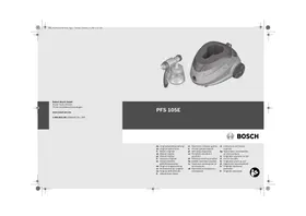
PFS 105E - Paint gun BOSCH - Free user manual and instructions
Find the device manual for free PFS 105E BOSCH in PDF.
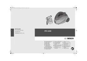



| Brand | BOSCH |
| Model | PFS 105E |
| Product type | Paint sprayer (fine spray system) |
| Rated power input | 350 W |
| Spray power | 105 W |
| Flow rate | 150 g/min |
| Tank volume | 800 ml (reversible 600 ml) |
| Hose length | 3.4 m |
| Weight (according to EPTA) | 4.9 kg |
| Protection class | II (double insulation) |
| Sound pressure level | 74 dB(A) (uncertainty K=1.5 dB) |
| Vibration (hand-arm) | < 2.5 m/s² |
| Power supply | 230 V ~ , 50 Hz (mains) |
| Adjustable spray pattern | Vertical flat, horizontal flat, round |
| Air flow adjustment | Continuous adjustment wheel |
| Material quantity adjustment | 3 positions (I, II, III) |
| Main functions | Spraying of paints, varnishes, glazes, oils, plant protection products |
| Maintenance and cleaning | Clean with appropriate thinner after each use; replace air filter if clogged |
| Safety | Safety stop via switch; protection against high-pressure jets |
| Spare parts and repairability | Parts available via Bosch after-sales service; repair by qualified personnel |
| General information | Manual available in several languages; spray time for 5 m²: approximately 6 min |
Frequently Asked Questions - PFS 105E BOSCH
User questions about PFS 105E BOSCH
0 question about this device. Answer the ones you know or ask your own.
Ask a new question about this device
Download the instructions for your Paint gun in PDF format for free! Find your manual PFS 105E - BOSCH and take your electronic device back in hand. On this page are published all the documents necessary for the use of your device. PFS 105E by BOSCH.
USER MANUAL PFS 105E BOSCH
Power Tools Division
70745 Leinfelden-Echterdingen
www.bosch-pt.com
1609929L50(2008.02)PS/304
PFS 105E

BOSCH
de Originalbetriebsanleitung en Original instructions fr Notice originale es Manual original pt Manual original it Istruzioni originali nl Oorspronkelijke gebruiksaanwijzing da Original brugsanvising sv Bruksanvisning i origina no Original driftsinstruks fi Alkuperäiset ohjeet
el Πρωτότυπο οδηγιών χρήσης tr Orijinal işletme talimatı pl Instrukcja oryginalna cs Původním návodem k používání sk Pôvodný návod na použitie hu Eredeti használati utasítás ru Оригинал инструкции по эксплуатации uk Оригінальна інструкція з експлуатації
ro Instrucțiuni de folosire originale bg Оригинално ръководство за експлоатация sr Originalno uputstvo za rad sl Izvirna navodila hr Originalne upute za rad et Algupärane kasutusjuhend lv Originala lietošanas pamācība lt Originali instrukcija

Deutsch . 7
English. 18
Français. 29
Español. Página 41
Português. Página 52
Italiano.. 63
Dutch.. 75
Danish. 86
Swedish Page 96
Norwegian . Page 106
Finnish. .Page 116
Greek Page 126
Turkish Page 138
Polish . Page 149
Czech Page 161
Slovak. Page 171
Hungarian .Page 183
Russian .. Page 194
Ukrainian. Page 206
Romanian . 218
Bulgarian ... Page 229
Serbian. Page 240
Slovenian. Page 251
Dr. Egbert Schneider Senior Vice President Engineering
Dr. Eckerhard Strötgen Head of Product Certification
ppa. 11. i.v. uogcu
06.02.2008, Robert Bosch GmbH, Power Tools Division D-70745 Leinfelden-Echterdingen
Assembly
General Power Tool Safety Warnings
WARNING
Read all safety warnings, instructions including Material
Safety Data Sheets (MSDS), and container labels provided with the paints and solvents.
Failure to follow the warnings and instructions may result in electric shock, fire and/or serious injury.
Save all warnings and instructions for future reference.
The term "power tool" in the warnings refers to your mains-operated (corded) power tool or battery-operated (cordless) power tool.
1) Workplace safety
a) Keep children and bystanders away while operating a power tool. Distractions can cause you to lose control.
2) Electrical Safety
a) The plugs of power tools must match the outlet. Never modify the plug in any way. Do not use any adapter plugs with earthed (grounded) power tools. Unmodified plugs and matching outlets will reduce the risk of electric shock. b) Protect the machine from rain and moisture. The penetration of water in a power tool increases the risk of electric shock. c) Do not misuse the cord. Never use the cord for carrying, pulling or unplugging the power tool. Keep cord away from heat, oil, sharp edges and moving parts. Damaged or entangled cords increase the risk of electric shock. d) When operating a power tool outdoors, use an extension cord suitable for outdoor use. Use of a cord suitable for outdoor use reduces the risk of electric shock. e) When operating the power tool in damp/ moist environments is unavoidable, use a residual current device (RCD). Use of a residual current device reduces the risk of electric shock.
3) Personal safety
a) Use safety equipment. Always wear eye protection. Safety equipment such as dust mask, non-skid safety shoes, hard hat, or hearing protection used for appropriate conditions will reduce personal injuries.
4) Use and care of the power tool
a) Do not use the power tool if the switch does not turn it on and off. Any power tool that cannot be controlled with the switch is dangerous and must be repaired. b) Store idle power tools out of the reach of children and do not allow persons unfamiliar with the power tool or these instructions to operate the power tool. Power tools are dangerous in the hands of untrained users. c) Use the power tool, accessories and application tools etc. in accordance with these instructions, taking into account the working conditions and the work to be performed. Use of power tools for operations different from those intended could result in a hazardous situation.
5) Service
a) Have your power tool serviced by a qualified repair person using only identical replacement parts. This will ensure that the safety of the power tool is maintained.
Safety Warnings for Fine-spray Systems
- Keep area clean well lit and free of paint or solvent containers, rags, and other flammable materials. Spontaneous combustion may occur. Fire extinguisher equipment shall be present and working at all times.
- Provide for good ventilation in the spraying area and for sufficient fresh air in the complete room. Evaporating inflammable solvents create an explosive environment.
Do not use materials with a flashpoint below 21°C for spraying and cleaning. Use water-based materials, non-volatile hydrocarbons or similar materials. Fast evaporating solvents create an explosive environment. Do not spray in the vicinity of ignition sources, such as static electricity sparks, open flames, pilot lights, hot objects, engines/motors, cigarettes and sparks from plugging in or unplugging power cords or operating switches. Such spark sources can ignite the spraying vicinity/environment. Do not spray any liquid of unknown hazard potential. Unknown materials can create hazardous conditions. Wear additional protective equipment such as appropriate protective gloves and protective masks or respirators when spraying or handling chemicals. Wearing protective equipment for the appropriate conditions reduces the exposure to hazardous substances.



- Never point the spray jet against yourself, towards other persons or animals. Keep your hands and other body parts away from the spray jet. If the spray jet should penetrate the skin, seek medical attention immediately from a doctor. The material being sprayed can even penetrate the skin through a glove and be injected into your body. Do not treat injection as a simple cut. High-pressure spray is able to inject toxins into the body and cause serious bodily injury. In the event that injection occurs, seek medical attention immediately.
Be aware of possible hazards from the spray material. Observe the information on drums/tanks/tins as well as manufacturer information of the spray material, including the request to wear personal protective equipment. The manufacturer's instructions are to be observed in order to reduce the risk of fire as well as injuries caused through toxins, carcinogens, etc. Use only nozzles/nozzle inserts specified by the manufacturer. Never spray without the nozzle protection mounted. Use of a special nozzle insert with the corresponding nozzle protection reduces the probability that a high-pressure jet penetrates the skin and injects toxins into the body. Exercise caution when cleaning and changing nozzle inserts. If the nozzle insert should become clogged during spraying, follow the manufacturer's instructions for switching off the system and relieving the pressure before removing the nozzle. Fluids under high pressure can penetrate the skin, inject toxins into the body and lead to serious injury. Keep the plug of the mains cord and the trigger switch of the spray gun clear of paint and other fluids. Never hold the cord by its connectors to support it. Failure to follow the instruction can lead to electric shock.
Functional Description

Read all safety warnings and all instructions. Failure to follow the warnings and instructions may result in electric shock, fire and/or serious injury.
Intended Use
The power tool is intended for atomising solvent-based and water-dilutable paints, finishes, primers, clear finishes, automotive finishes, staining sealers, wood sealer-preservatives, plant protectives, oil and disinfection agents. The power tool is not suitable for spraying dispersions and latex paint, caustic solutions, acidic coating materials, coating materials with granules or solids as well as spray and drip-impeding materials.
Use the machine only when you can fully assess all functions and handle them without limitation, or after having received appropriate instructions.
Noise/Vibration Information
Measured values determined according to EN 60745.
Typically the A-weighted sound pressure level of the product is 74 dB(A). Uncertainty K = 1.5 dB. The noise level when working can exceed 80 dB(A).
Wear hearing protection!
The hand-arm acceleration is typically below 2.5m / s2
Product Features
The numbering of the components shown refers to the representation of the power tool on the graphic pages.
1 Spray gun
2 Air cap 3 Union nut 4 Mark for SDS connection 5 Thumbwheel for spraying capacity 6 Hose port (spray gun) 7 Handle extension (only for 800 ml container) 8 Container for spray material, 800 ml Container for spray material, 600 ml* 9 Trigger switch
10 Suction tube with container seal green: for 800 ml container white: for 600 ml container*
11 Nozzle
12 Nozzle seal
13 Air hose
14 SDS connector
15 Base unit
16 Control knob for On/Off and air-flow control 17 Set-down port for spray gun 18 Hose connection (base unit) 19 Handle 20 Accessory compartment 21 Air filter cover 22 Measuring cup
*The accessories illustrated or described are not included as standard delivery.
English | 21
Technical Data
| Fine-spray System | PFS 105 E | |
| Article number | 3 603 B06 2.. | |
| Rated power input | W | 350 |
| Spraying capacity | g/min | 150 |
| Atomising output | W | 105 |
| Required time for 5 m² paint application | min | 6 |
| Container capacity for spray material | ml | 800 |
| Length of air hose | m | 3.4 |
| Weight according to EPTA-Procedure 01/2003 | kg | 4.9 |
Protection class
□/II
Please observe the article number on the type plate of your machine. The trade names of the individual machines may vary.
Declaration of Conformity
We declare under our sole responsibility that the product described under "Technical Data" is in conformity with the following standards or standardization documents: EN 60335 according to the provisions of the directives 2004/108/EC, 98/37/EC (until Dec. 28, 2009), 2006/42/EC (from Dec. 29, 2009 on).
Technical file at:
Robert Bosch GmbH, Dept. PT/ESC,
D-70745 Leinfelden-Echterdingen
Dr. Egbert Schneider
Dr. Eckerhard Strötgen
Senior Vice President
Head of Product
Engineering
Certification
06.02.2008, Robert Bosch GmbH, Power Tools Division
D-70745 Leinfelden-Echterdingen
Assembly
Before any work on the machine itself, pull the mains plug.
Connecting the Air hose
(see figures A1 - A2)
Take the air hose 13 out of the accessory compartment 20. - Remove the protective caps from both ends of the air hose.
Connecting to the spray gun:
- Firmly insert an SDS connector 14 of the air hose in alignment with the arrow mark into the hose port of the spray gun 6.
- Turn the SDS connector until the lock can be heard to latch.
Connecting the base unit:
- Firmly insert the second SDS connector of the air hose in alignment with the arrow mark into the port of the base unit 18.
- Turn the SDS connector until the lock can be heard to latch.
Note: After use, reattach the protective hose caps to the hose ends.
Operation
Preparing for Operation
Spraying on the sides of water bodies (lakes, rivers, etc.) or neighbouring surfaces in the direct catchment area is not permitted.
When purchasing paint, varnish and spray material, pay attention to their environmental compatibility.
Preparing the Spray Surface
Note: Cover off the vicinity of the spray surface thoroughly and generously.
The spray mist contaminates the environment. When spraying in enclosures, surfaces not covered can become contaminated.
The spray surface must be clean, dry and grease-free.
- Roughen smooth surfaces and then remove the sanding dust.
Diluting Spray Material
- When diluting, pay attention that the spray material and the diluting agent correspond. When using a faulty diluting agent, lumps can develop that can lead to clogging of the spray gun.
| Spray material | Recommended dilution |
| Wood preservatives, strip-pers, oils, finishes | undiluted |
| Disinfectants, plant protectants | undiluted |
| Solvent- or water-dilutable paints, primers, automobile spray paint, thick-coat finishes | At least 10 % diluted |
For spray material that needs to be diluted, proceed as follows:
Take the measuring cup 22. - Stir the spray material thoroughly. - Fill a sufficient quantity of spray material into the spray-material container 8. (see "Filling in Spray Material", page 22) - Dilute the spray material by 10% with paint thinner. Examples:
| Amount of spray material [ml] | 200 | 300 | 400 | 500 |
| Paint thinner [ml] | 20 | 30 | 40 | 50 |
- Stir the spray material thoroughly.
- Carry out a test-spray run on a test surface. (see "Spraying", page 23)
When the spraying pattern is perfect, start the spray job.
or
When the spraying result is not satisfactory or when no paint comes out, please continue as described under "Correction of Malfunctions" on page 26.
Filling in Spray Material (see figures C1-C2)
Before any work on the machine itself, pull the mains plug. - Unscrew the container 8 from the spray gun. - Turn the suction tube 10 so that the spray material can be sprayed with almost no residue:
| For spray jobs on horizontal surfaces/objects | toward the frontin nozzle direction |
| For spray jobsoverhead | toward the rear inhandle direction |
- Fill the spray material into the container and screw the container firmly to the spray gun.
English | 23
Starting Operation
Observe correct mains voltage! The voltage of the power source must agree with the voltage specified on the nameplate of the machine. Power tools marked with 230 V can also be operated with 220 V. During operation, the base unit must always stand horizontally on a level surface. Never tilt the base unit or set it upright when switched on. Pay attention that the base unit cannot draw in dust or other contamination during operation. Make sure never to spray on the base unit.
Switching On
Always place the base unit horizontally on a level and clean surface. - Plug the mains plug into a socket outlet. - Grasp the spray gun by the handle and point it at the spray surface. - For switching on, turn the control knob 16 on the base unit toward the right to the stop. It is recommended to start with the maximum air flow. ("Adjusting the Air Flow", see page 24) - Pull the trigger switch 9 on the spray gun.
Note: When the base unit is switched on, air always flows out at the nozzle 11.
Switching Off
- Release the trigger switch 9 and turn the control knob 16 toward the left to the stop.
- Place down the spray gun in the set-down port 17.
- Pull the mains plug from the socket outlet.
Working Advice
Spraying (see figures D-E)
Note: Observe the wind direction when operating the power tool outdoors.
- Firstly, carry out a test-spray run and adjust the spray pattern and the spray material quantity according to the spray material. (For adjustments, see the following sections)
- Make sure to hold the spray gun vertical to the spray object at a uniform clearance between 5 - 15 cm.
- Begin the spraying procedure outside the target area.
- Move the spray gun evenly cross-wise or up-and-down, depending on the spray pattern setting.
An even surface quality is achieved when the paths overlap by 4 - 5 cm
- Avoid interruptions inside the target area. An even movement of the spray gun results in an even surface quality. Non-uniform clearance and spray angle lead to heavy formation of paint mist and thus to an uneven surface.
- End the spraying procedure outside the target area.
Never spray the container completely empty.
When the suction tube no longer immerses in the spray material, the spray jet will break off, resulting in a non-uniform surface.
When coating material builds up on the nozzle and air cap, clean both parts with the corresponding solvent.
Adjusting the Spray Pattern (see figure F)
- Never actuate the trigger switch 9 while adjusting the air cap 2.
- Loosen the union nut 3.
- Turn the air cap 2 to the requested position.
- Firmly retighten the union nut.
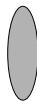
Air cap Jet
Application


A
Vertical flat jet for horizontal working direction


B
Horizontal flat jet for vertical working direction


Round jet for corners, edges and hard to reach locations
Adjusting the Spraying Capacity (see figure G)
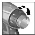
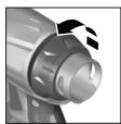
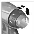
- To adjust the requested spraying capacity, turn the thumbwheel 5:
I: Min. spraying capacity,
III: Max. spraying capacity.
Spraying capacity
Adjustment
Too much material on target area:
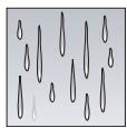
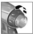
The spraying capacity must be reduced.
- Turn the thumbwheel 5 in direction I.
Not enough material on target area:
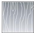
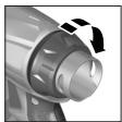
The spraying capacity must be increased.
Turn the thumbwheel 5 in direction III.
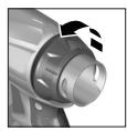
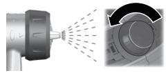
Adjusting the Air Flow (see figure H)
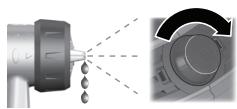
- Turn control knob 16 to adjust the air flow and the pressure for the spray material being used.
| Minimal air flow | Maximum air flow |
It is recommended to start with the maximum air flow.
Air Flow
Adjustment
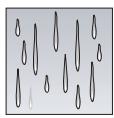
Too much fog of coating material:
The air flow must be reduced.
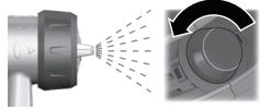
- Turn control knob 16 toward the left.
Atomisation too coarse:
The air flow must be increased.
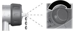
- Turn control knob 16 toward the right.
Transport
The filled spray gun or a closed container with spray material can be placed in the set-down port 17 for transport. The holding fixture retains the spray gun firmly in the set-down port. Spray material cannot run out.
- Place the spray gun on the set-down port and push it in against the resistance until it is tightly seated.

English | 25
Maintenance and Service
Maintenance and Cleaning
Before any work on the machine itself, pull the mains plug.
Cleaning (see figures I-K)
Proper cleaning is the requirement for flawless operation of the spray gun. Improper or lack of cleaning voids warranty claims.
Always clean the spray gun and the container with the respective diluting agent (paint thinner or water) for the spray material being used.
Never immerse the complete spray gun into the cleaning agent.
Never clean the nozzle and air holes of the spray gun with pointed metal objects.
Do not pour diluted spray material back into the original spray material drum/tin for storage.
Clean the spray gun thoroughly after having sprayed material hazardous to one's health.
- Switch the base unit off and pull the trigger switch 9 of the spray gun so that the spray material can flow back into the container.
- Unscrew the container 8 and empty the remaining spray material.
- Fill diluting agent (paint thinner or water) into the container and screw it to the spray gun.
- Shake the spray gun several times.
- Switch the base unit on and spray the diluting agent into an empty material tin.
- Repeat the last three steps until clear diluting agent emerges from the spray gun.
- Switch the base unit off again.
- Completely empty the container 8.
- Check if the suction tube with the container seal 10 is free of spray material and undamaged.
- Clean the outside of the container and the spray gun with a cloth moistened in paint thinner.
- Unscrew the union nut 3 and the air cap 2.
- Clean the nozzle 11 and the nozzle needle with diluting agent.
From time to time, the nozzle seal 12 must also be cleaned.
- Remove the nozzle 11 and the nozzle seal 12. If required, use a pointed object, as the nozzle seal is seated firmly to the spray gun.
- Clean the nozzle seal with diluting agent.
- Reinstall the nozzle seal in the spray gun. Pay attention that the groove points away from the spray gun.
- Mount the nozzle onto the spray gun body and turn it to the correct position.
- Mount the air cap 2 onto the nozzle and tighten with the union nut 3.
Changing the Air Filter (see figure L)
The air filter must be replaced when soiled.
- Remove the air filter cover 21.
- Change the air filter.
- Remount the air filter cover.
Material Disposal
Diluting agent and remainders of spray material must be disposed of in an environmentally-friendly manner. Observe the manufacturer's disposal information and the local regulations for disposal of hazardous waste.
Chemicals harmful to the environment may not be disposed of into soil, groundwater or bodies of water. Never pour chemicals harmful to the environment into the sewerage system!


Correction of Malfunctions
| Problem | Cause | Corrective Measure |
| Spray material does not cover properly | Spraying capacity too low | Turning the thumbwheel 5 in direction III |
| Clearance to target area too large | Reduce spray distance | |
| Not enough spray material on target area, too few spray paths sprayed over target area | Apply more spray paths over target area | |
| Spray material too viscous | Thin down the spray material by 10% again and carry out a test-spray run | |
| Spray material runs off after coating | Too much spray material applied | Turning the thumbwheel 5 in direction I |
| Clearance to target area too close | Increase spray distance | |
| Viscosity of spray material too low | Add original spray material | |
| Spray material applied too often over same spot | Remove spray material; reduce number of spray paths over same spot | |
| Atomisation too course | Spraying capacity too high | Turning the thumbwheel 5 in direction I |
| Air flow too low | Turn control knob 16 toward the right | |
| Nozzle 11 soiled | Clean nozzle | |
| Too little pressure build-up in container 8 | Screw container firmly against spray gun | |
| Spray material too viscous | Thin down the spray material by 10% again and carry out a test-spray run | |
| Air filter heavily soiled | Changing the Air Filter | |
| Too much fog of coating material | Too much spray material applied | Turning the thumbwheel 5 in direction I |
| Clearance to spray surface too large | Reduce spray distance | |
| Viscosity of spray material too low | Reduce air flow; turn control knob 16 toward the left |
| Problem | Cause | Corrective Measure |
| Spray jet pulsates | Not enough spray material in container | Refill spray material |
| Venting hole on suction tube 10 clogged | Clean suction tube and hole | |
| Air filter heavily soiled | Changing the Air Filter | |
| Spray material too viscous | Thin down the spray material by 10% again and carry out a test-spray run | |
| Spray material drips from the nozzle | Build-up of spray material on nozzle 11 and air cap 2 | Clean nozzle and air cap |
| Nozzle 11 worn | Replace nozzle | |
| Nozzle 11 loose | Tighten union nut 3 | |
| No spray material emerges from the nozzle | Control knob 16 for air-flow control turned too far to the left | Turn control knob 16 toward the right |
| No pressure build-up in container 8 | Screw container firmly against spray gun | |
| Suction tube 10 loose | Insert suction tube properly | |
| Nozzle 11 clogged | Clean nozzle | |
| Suction tube 10 clogged | Clean suction tube | |
| Venting hole on suction tube 10 clogged | Clean suction tube and hole | |
| Spray material too viscous | Thin down the spray material by 10% again and carry out a test-spray run |
Maintenance
If the machine should fail despite the care taken in manufacturing and testing procedures, repair should be carried out by an after-sales service centre for Bosch power tools.
In all correspondence and spare parts order, please always include the 10-digit article number given on the type plate of the machine.
WARNING! Important instructions for connecting a new 3-pin plug to the 2-wire cable.
The wires in the cable are coloured according to the following code:

Do not connect the blue or brown wire to the earth terminal of the plug.
Important: If for any reason the moulded plug is removed from the cable of this power tool, it must be disposed of safely.
28 | English
After-sales Service and Customer Assistance
Our after-sales service responds to your questions concerning maintenance and repair of your product as well as spare parts. Exploded views and information on spare parts can also be found under:
www.bosch-pt.com
Our customer consultants answer your questions concerning best buy, application and adjustment of products and accessories.
Great Britain
Robert Bosch Ltd. (B.S.C.)
P.O.Box 98
Broadwater Park
North Orbital Road
Denham
Uxbridge
UB 95HJ
Tel. Service: +44 (0844) 736 0109
Fax: +44 (0844) 736 0146
Australia, New Zealand and Pacific Islands
Robert Bosch Australia Pty. Ltd.
Power Tools
Locked Bag 66
Clayton South VIC 3169
Customer Contact Center
Inside Australia:
Phone: +61 (01300) 307 044
Fax: +61 (01300) 307 045
Inside New Zealand:
Phone: +64 (0800) 543 353
Fax: +64 (0800) 428 570
Outside AU and NZ:
Phone: +61 (03) 9541 5555
www.bosch.com.au
1609929L50|(12.2.08)
Disposal
Spray gun, base unit, accessories and packaging should be sorted for environmental-friendly recycling.
The plastic components are labelled for categorized recycling.
Only for EC countries:

Do not dispose of power tools into household waste! According to the European Guideline 2002/96/EC for Waste Electrical and Electronic Equipment and its implementation into national
right, power tools that are no longer usable must be collected separately and disposed of in an environmentally correct manner.
Subject to change without notice.
Dr. Egbert Schneider Dr. Eckerhard Ströttgen Senior Vice President Head of Product Engineering Certification
06.02.2008, Robert Bosch GmbH, Power Tools Division D-70745 Leinfelden-Echterdingen
Montage
Robert Bosch (France) S.A.S.
Robert Bosch GmbH, Dept. PT/ESC,
D-70745 Leinfelden-Echterdingen
Dr. Egbert Schneider
Dr. Eckerhard Strötgen
Senior Vice President
Head of Product
Engineering
Certification
06.02.2008, Robert Bosch GmbH, Power Tools Division
D-70745 Leinfelden-Echterdingen
Assembly
Dr. Egbert Schneider Senior Vice President Engineering
Dr. Eckerhard Ströttgen Head of Product Certification
06.02.2008, Robert Bosch GmbH, Power Tools Division D-70745 Leinfelden-Echterdingen
Assembly
- Before all work on the power tool, pull the mains plug out of the socket.
Connect the air hose (see figures A1-A2)
Dr. Egbert Schneider Dr. Eckerhard Ströttgen Senior Vice President Head of Product Engineering Certification
ppa. Mee
06.02.2008, Robert Bosch GmbH, Power Tools Division D-70745 Leinfelden-Echterdingen
Assembly
Robert Bosch GmbH, Dept. PT/ESC,
D-70745 Leinfelden-Echterdingen
Dr. Egbert Schneider
Dr. Eckerhard Strötgen
Senior Vice President
Head of Product
Engineering
Certification
06.02.2008, Robert Bosch GmbH, Power Tools Division
D-70745 Leinfelden-Echterdingen
Technical data
Robert Bosch GmbH, Dept. PT/ESC,
D-70745 Leinfelden-Echterdingen
Dr. Egbert Schneider
Senior Vice President
Engineering
Dr. Eckerhard Strötgen
Head of Product
Certification

06.02.2008, Robert Bosch GmbH, Power Tools Division
D-70745 Leinfelden-Echterdingen
Assembly
Bosch Service Center
Telegrafvej 3
2750 Ballerup
Tel. Service Center: +45 (04489) 8855
Fax: +45 (04489) 8755
E-Mail: vaerktoej@dk.bosch.com

Dr. Egbert Schneider Senior Vice President Engineering
Dr. Eckerhard Strötgen Head of Product Certification
06.02.2008, Robert Bosch GmbH, Power Tools Division D-70745 Leinfelden-Echterdingen
Assembly
Pull the plug out of the socket before carrying out any work on the power tool.
Dr. Egbert Schneider Senior Vice President Engineering
Dr. Eckerhard Ströttgen Head of Product Certification
06.02.2008, Robert Bosch GmbH, Power Tools Division D-70745 Leinfelden-Echterdingen
Assembly
Dr. Egbert Schneider Senior Vice President Engineering
Dr. Eckerhard Ströttgen Head of Product Certification

06.02.2008, Robert Bosch GmbH, Power Tools Division D-70745 Leinfelden-Echterdingen
Assembly
Instructions for use and safety
The measured values were determined in accordance with EN 60745.
The typical A-weighted sound pressure level of the tool is determined in accordance with the standard and is 74 dB(A).
Uncertainty K=1.5 dB.
When working, the noise level may exceed 80 dB(A).
Wear ear protection!
The typical hand-arm vibration value is less than 2.5 m/s².
Declared data
The numbering of the declared data is based on the representation of the power tool on the pages with the graphics.
1Iiotol yekaooou
Senior Vice President Engineering
Head of Product Certification
06.02.2008, Robert Bosch GmbH, Power Tools Division D-70745 Leinfelden-Echterdingen
Read the operating instructions before using the power tool.
We reserve the right to make changes.
Greece
Robert Bosch A.E.
Kifisou 162
12131 Peristeri-Athens
Tel.: +30 (0210) 57 01 200 CENTER
Tel.: +30 (0210) 57 70 081 - 83 CENTER
Fax: +30 (0210) 57 01 263
Fax: +30 (0210) 57 70 080
www.bosch.gr
ABZ Service A.E.
Tel.: +30 (0210) 57 01 375 - 378 SERVICE
Fax: +30 (0210) 57 73 607
Bosch Power Tools
1609929L50|(12.2.08)

Dr. Egbert Schneider Dr. Eckerhard Ströttgen Senior Vice President Head of Product Engineering Certification
ppa. Maee i.v. Nogcu
06.02.2008, Robert Bosch GmbH, Power Tools Division D-70745 Leinfelden-Echterdingen
Montaj
Bosch San. ve Tic. A.S.
Ahi Evran Cad. No:1 Kat:22
Polaris Plaza
80670 Maslak/Istanbul
Müsteri Danismani: +90 (0212) 335 06 66
Müsteri Servis Hatti: +90 (0212) 335 07 52
1609929L50|(12.2.08)
Bosch Power Tools
Polski | 149
Dr. Egbert Schneider Senior Vice President Engineering
Dr. Eckerhard Ströttgen Head of Product Certification

06.02.2008, Robert Bosch GmbH, Power Tools Division D-70745 Leinfelden-Echterdingen
1609929L50|(12.2.08)
Bosch Power Tools
Polski | 153
Montaž
Robert Bosch Sp. z o.o.
Dr. Egbert Schneider Dr. Eckerhard Ströttgen Senior Vice President Head of Product Engineering Certification
ppa. 11. i.v. uogcu
06.02.2008, Robert Bosch GmbH, Power Tools Division D-70745 Leinfelden-Echterdingen
Montáž
Before any work on the power tool, pull the plug out of the socket.
Bosch Service Center PT
K Vapence 1621/16
692 01 Mikulov
Tel.: +420 (519) 305 700
Fax: +420 (519) 305 705
E-Mail: servis.naradi@cz.bosch.com
www.bosch.cz
Slovak | 171
General Warning Notices and Safety Instructions
CAUTION
Dr. Egbert Schneider Dr. Eckerhard Ströttgen Senior Vice President Head of Product Engineering Certification
06.02.2008, Robert Bosch GmbH, Power Tools Division D-70745 Leinfelden-Echterdingen
Assembly
Dr. Egbert Schneider Dr. Eckerhard Strötgen Senior Vice President Head of Product Engineering Certification
06.02.2008, Robert Bosch GmbH, Power Tools Division D-70745 Leinfelden-Echterdingen

Assembly
a) Do not work with a power tool with a defective switch. A power tool that cannot be switched on or off is dangerous and must be repaired.
Russian | 195
b) Store unused
Power tools must be kept out of reach of children. Do not allow persons unfamiliar with the tool or these instructions to operate the tool.
Power tools are dangerous in the hands of untrained users.
c) Use the power tool, accessories and tool bits etc., in accordance with these instructions.
Take into account the working conditions and the work to be performed.
Use of the power tool for operations different from those intended could result in a hazardous situation.
5) Service
a) Have your power tool serviced only by
qualified personnel
only with original spare parts
preserve the safety of the instrument.
Safety instructions
for thin-layer
spreading systems
Keep your work area clean and well lit. Remove containers for paint or solvent, waste, and all flammable materials.
There is a risk of fire or explosion. Always keep fire extinguishers and fire-fighting devices ready.
Ensure good ventilation in the spreading area and sufficient
supply of fresh air throughout the room. Evaporation of flammable solvents creates an explosive atmosphere.
Do not use sprays or cleaning
materials with a flash point
below 21 °C. Use water-based materials,
difficult-to-ignite hydrocarbons, or
similar materials. Aerosols,
evaporating solvents create
B3pbIBOOHAcHYo aTMocdepey.
He pacTbIAJTe B TpeDeIax HcToHnKOB
BOCTIaMeHeHHa, KaK To, CTaTHueCKy
3AnektpoHcKp,OTKpbITOrO TAmEHn
HnHcHpyUoIero TAmehn, ropaynx
PpeAeTOB, ABHrAteIeN, CNrapET H NCKp OT
couIeHEnn npacUeHEnn
3Aektpoka6eH Hn 3aedCTBOBa
BbIKIOuATEeIe. TaKne HcTOUHNK INCKp
MOrTy TIPINBECTN K BOCTIaMeHeHHIO
He pactblaIaIte MaTepeHaIbI, ONaCHOcTb
KOTOpbIX HEN3Bectha. He3HaKombie
MaTePnaIbI MOrYT CO3aTb OTaChBle ycAoBnA.
PpIMeHnTe OToTOAnHTeAbHbIe,
HNDNBDAyAaHbIe,3aUNTHbIe CpeDCTBa,KaK
TO, COOTBETCTBYUOUNHe 3aunTHbIe IepuATKn
H3aunTHbIe HAN DbIXaTeAbHbIe cHbIb
MACKNIINpaCTbIAEHHXHMHueCKNX
Beweuctb pa6oTe c HmM. PpimHeHne
3aunthbIX CPeACTB AAR COOTBETCTBYUOHNX
YCAOBH CNXKaET BO3MOXHOCTb BO3eJCTBnA
OTTachbIX BeseCTB.



He hantpaBraIte paCtbIAHOUyO CTpyuHa ce6A, APyrHx AHU HAN XHBOTHbIX.
AepKntecb BdaaN OT paCtblaAIOuei CTpyn.
EcAn pacTbIaIouaA cTpy Ipo6bet Koxy,
To cpa3y 6paHTecb K BpaCy. Ctpy MoKeT
Ipo6ntb koxy daxe uepe3 nepaTkn H
BtpbichyBampactbIaemoeBeuecTeBO.
He paccMaTpNbAaTe TaKoe BnPbIckNBAHne KaK IpoCToe paHenHe KOxN. Ctpy BbICOKO O DaBLeHn MoKeT BnPbIcHytB Bam RaOBHTbIe BeIecTBa N IIpNBecTN K cepBe3HbIM paHENrM. B cLuyae BnPbIcKa uepe3 KOxH HeMeDAnHNo 6bpaNTecb K BpaCy 3a TOMOuJIO. YuHTbIBAIte BO3MOXHbIe OIaNCHOT, IcxOJaIne OT paCTbIaHEmoro BeIecTBA. YuHTbIBAIte MapKnPbOBky Ha EMKoCTx HAn HnΦOpMaunn H3rTOBHTeApaCTbIAHEmoro BeIeCTBA,BkIoua Tpe6OBaHne TPImHeHnHaHbHApAaHbHbIX 3aUHTbIX CpeACTB.BblIOHaIYe yka3AHn H3rTOBHTeA,yTO6bl CH3NtB pNCK ToLayueHn TpaBM,Bbl3BaHHbIX IOXapOM, RaAMn,KaHcpeOReHaMn nT.I. PpIMeHnTe ToIbKO CteuHcHnHPOBaHhbIE n3rTOBHTeLEM Ha6Opbl CoTEn. HNKoTa He pa6OtaTe c pacTbIaNTeLEM 6ez yCTaHOBHeHoi COIIAOBo 3aunTbI. PpIMeHne CteuaHaBHO rcoTALOBOro Ha6opa C COOTBeTCTByUoSei COIIAOBo 3aunToCHNJaet BepoAHTHOCTb Ipo6oKoXn CTpye BbICOKO DAABeHHN N BIPpbICKNbAHn RAIOB. Octopoxho np ouhctke n cmehe coTIObIX na6oob. Ecn np pactbIeHH 3acopHTcR coTIOBbI na6op,TOpeA ydaIeHem COIIa dA ONUCTKN BbIIOAHHTe Yka3AHN I3r0OBtAEI IO BBkAUOeHHIO HCTpymeta n CHATNO daBaeHH. IOD BbICOKHM DaBaeHHem XnKocTH MOryT IIpo6ntb KoKxy N BTPbcHcyTB RaB TELO, UTO BeDet K cepbe3HbIM paHeHHM. DepxKHe Bnky shhpya cetn H KhoTky BbIKIOUcATEA INCTOLeTa-pacIbIANTeA B ChCTOTE OT Kpacku IN DpyrNx JnKoCteH. He DepxKHe SHyP DA NTOAdepkKn Ha 7TeTceAbHom CoeHNHeHH. YTuJeHHa PtN CO6AnDeHHM MOY T IOBaeBy 3a Co60i 3AEKTpueeCKoe IopaxHeHne.
OtncaHne yHKcnn

Noise values determined in accordance with EN 60745.
Measurements were carried out in accordance with EN 60745.
The A-weighted noise level of the power tool is typically 74 dB(A). Measurement uncertainty K = 1.5 dB.
The noise level at the workplace may exceed 80 dB(A).
Use hearing protection!
The weighted acceleration is typically less than 2.5 m/s².
Russian | 197
Illustrated components
The numbering of the components refers to the illustration on the graphics page.
1 Spray gun
13 Air cap
15 Base block
2 Air cap ring 3 Trigger lock 4 Marking for SDS lock 5 Adjustment knob for paint quantity 6 Connection for hose (spray gun) 7 Extension hose (only for 800 ml cup) 8 Cup for spray material, 800 ml Cup for spray material, 600 ml* 9 Trigger 10 Cup seal stand green: for 800 ml cup white: for 600 ml cup* 11 Nozzle 12 Nozzle seal 14 SDS lock 16 Handle for switching on/off and adjusting air flow 17 Air supply for spray gun 18 Connection for hose (base block) 19 Handle 20 Air filter compartment 21 Cover of air filter 22 Cup scale *Illustrated or described accessories are not included in the standard delivery.
Technical data
Dr. Egbert Schneider Dr. Eckerhard Ströttgen Senior Vice President Head of Product Engineering Certification
06.02.2008, Robert Bosch GmbH, Power Tools Division D-70745 Leinfelden-Echterdingen
Assembly
Before starting any maintenance work on the power tool, pull the mains plug out of the socket.
Note: The surface to be processed must be protected carefully.
Aerosols can contaminate the surroundings. When working in enclosed rooms, all unprotected surfaces can become contaminated.
The surface to be processed must be clean, dry, and free of grease.
- First, roughen the surfaces and then clean them of sanding dust.
Dilution of the material to be sprayed
When diluting, pay attention to the combination of the material to be sprayed with the solvent. If an incorrect solvent is used, lumps may form which clog the spray gun.
Material to be sprayed
Recommended dilution
Wood preservative, stain, oil, sealing paint
Undiluted
Thinner, paint protection agent
Dilutable
Diluted
not diluted
solvent-based paints,
less than 10%
primers, topcoats,
automotive paints,
disinfecting paints for
rabbit cage material (see fig. C1-C2)
Before starting maintenance work on the electric tool, unplug it from the power outlet. Remove the cup from the spray gun. Turn the gun so that the material can be sprayed without residue.
Application instructions
Spraying (see fig. D-E)
Note: When using the electric tool outdoors, take the wind direction into account.
- First perform a test spray to adjust the spray pattern and material feed. (Adjustment values are given in the following sections.)
- Hold the spray gun at a distance of 5-15 cm vertically to the surface to be painted. Start spraying from the top of the surface. Move the gun according to the spray pattern, evenly across or up and down. An even surface quality is achieved by overlapping strokes by 4-5 cm. Do not interrupt spraying within the area to be painted.
The spray pattern of the spray gun ensures uniform surface quality.
Uneven distance and angle of the spray gun lead to fog formation and, as a result, to an uneven surface.
The spraying process must be completed within the specified limits to ensure proper surface treatment.
Do not completely empty the spray material from the cup. If the gun is not triggered with spray material, the spray mist is interrupted and an uneven surface occurs.
Accumulated spray material on the nozzle and air cap should be removed with the used thinner.
Adjusting the spray pattern (see Fig. F)
Do not activate the trigger 9 when adjusting the air cap 2.
- Release the locking ring 3. Turn the air cap 2 to the desired position. Tighten the locking ring firmly.
Air cap

A
Vertical spray pattern
For horizontal work


B
Horizontal spray pattern


For vertical work
Cyrillic script and Latin, edges and places of use


Russian | 201
Adjusting the amount of sprayed material (see fig. G)
Turn the adjusting knob 5 until the desired amount of sprayed material is set: I: minimum amount, III: maximum amount.
Amount of sprayed material
Too much material has been applied:
Adjustment
Reduce the amount of sprayed material.
Increase the amount of sprayed material.
-Turn the adjusting knob 5 in the direction of III.
Air consumption
Strong fog or droplets:
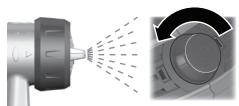
Adjustment
Reduce air consumption.
-Turn the handle 16 to the left.
Increase air consumption.
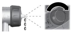
Increase air flow.
I. F. Potorokhin, 14,
620017, Yekaterinburg
Tel.: +7 (0343) 3658674
Tel.: +7 (0343) 3787756
Fax: +7 (0343) 3787928
Belarus
ACU IP-18
220064 Minsk, st. Kurchatova, 7
Tel.: +375 (017) 210 29 70
Fax: +375 (017) 207 04 00
Utilization
The product-sprayer, base unit, accessories and packaging should be sent to an ecological recycling center.
For sorting of waste during utilization, the details of synthetic materials are marked accordingly.
ToIbKO DAa CTpaH-uaHeOB EC:

He BbI6paCbIBaIte 3eKtpoHnHCTpyMeHTbl B KOMMyHaIbHbI Mycop!
Corgacho Ebponecko DnpeKtBe 2002/96/EC o ctabix 3eKtpn-uecknx n 3eKtpoHHblx
HNCTPymeHTax INPn6bopax, a TaKxE O PnpeTBOpeHHN 3TOI AnpeKTHBbl B HauNoHaNbHOe PpaBO,OTCAUYKBWNE CBOI CpOK 3AKeKTPoHNCTpymeHTblDOLXHBIO TDeAIBHO Co6HpTaBCn I CdaBaTbcn Ha3KOLOrHueCKN UCHTyO yTHnU3aUHO.
OCTABLAEM 3a co6oI IpaBo Ha H3MeHEnHa.


3araIbHI IIOIpeEKeHHA AIAeLEKTPoPpHaAdiB
TONEPEDXEHHA IpouHTaTe IpaBnAa 3
BkazIBKN, BkAIOUaOuN DOaHl Do foap6 i po3unHHKIB TACIOPTa 6e3neKn peoBHn I TOtepeXyBaIbHi Ta6AnuKN Ha EMHOCTAx.
HeBnKoHaHHaPbAIN3TexHIX6e3neKnIBkazIOKMOKeIpN3BOADHTDOyApyeEeKtpnHmCTpyMOM,poXekiTa/a6oBaJknxTpaBM.
36epiraTte Bci IpaBnla 3 Texhikn 6e3neKn i Bka3iBkn Ha MaJ6yTHc.
TIIД TIOHHTTREM «eAekTpOPIpHaA»,IIO BHKOPNCTOByETbCABITpaBnAax 3TexHikN 6e3IeKNaMaTbCnHaYBa3i eAekTpOPIpHaA,Io Tpauoe BiMpekxi (3 eAektpoka6eMe) a6o BiAcMyAANTropHoBiataapei (6e3 eAekTpoka6eIIO).
Hymepaia 3o6paKeHHX KOMTOHEHTIB TocnAeTbCn Ha 3o6paKeHHeAeKTPoPpHaNy Ha CTOpIHkax 3 MaIOHKMn.
1 TictoAet-p03nIIOBau
13 TObitpHm ⅢAaHr
15 Ba3OBn By3Oa
2 Trigger nozzle 3 Trigger 4 SDS chuck 5 Locking screw for adjustable material 6 Adjustment (spraying) 7 Nozzles (for tanks up to 800 ml) 8 Tank for spray material, 800 ml Tank for spray material, 600 ml 9 Trigger 10 Tube for locking with tank lid: for tanks up to 800 ml: for tanks up to 600 ml 11 Nozzle 12 Adjustable nozzle 14 Adjustment 16 Swivel handle for switching on/off and adjusting quantity of air 17 Storage for spray pistol 18 Connection for hose (base unit) 19 Handle 20 Spray lance sections 21 Cover of air filter 22 Measuring cup *The illustration and description of the device do not belong to the standard delivery scope.
Technical data
| Mikropo3ПИЮВаьнacnTeMa | PFS 105 E | |
| Товарни homер | 3 603 B06 2.. | |
| HOM. сpoживаHAпOTужнICTь | Вт | 350 |
| ПOTужнICTь пОдчi | r/xВи. | 150 |
| ПOTужнICTь рОЗПиLEннЯ | Вт | 105 |
| ВИтраTiч acу на 5 M2фapбовOrо пОкрпTTя | xВи. | 6 |
| ОБ'Ем 6aЧka дЯроЗпсkyванOrо materiэу | МА | 800 |
| Довжина пОВітравиношланга | M | 3,4 |
| Bara BiДПОВIДно доЕPTA-Procedure01/2003 | КГ | 4,9 |
Classification
□/II
Please refer to the type plate on your electric tool for the article number. The trade name of individual devices may vary.
Declaration of Conformity
We declare under our sole responsibility that the product described in the 'Technical Data' complies with the following standards or normative documents: EN 60335 in accordance with the provisions of Directives 2004/108/EG, 98/37/EG (until 28.12.2009), 2006/42/EG (after 29.12.2009).
Technical documents at: Robert Bosch GmbH, Dept. PT/ESC, D-70745 Leinfelden-Echterdingen
Dr. Egbert Schneider Dr. Eckerhard Ströttgen Senior Vice President Head of Product Engineering Certification
ppa. Maee i.v. Nogcu
06.02.2008, Robert Bosch GmbH, Power Tools Division D-70745 Leinfelden-Echterdingen


Assembly
Before any work on the electric tool, pull the plug out of the socket.
Protective devices for wood, metal, and varnish
Do not forget
Undiluted
Lacquers can be diluted
Minimum
with thinners or water, primers, automotive coatings, thick-layer varnishes
Dilution
Dilute the ready-to-use material as follows:
Take a measuring cup 22. - Mix the diluted material thoroughly. - Pour enough diluted material into the container for diluted material 8. (See "Filling the diluted material", page 211)
- Dilute the diluted material
- diluted by 10%. Example:
Drops for hard-to-reach places
Ukrainian | 213
Adjust the viscosity of the diluted material (see Fig. G)
of the diluted material.
-Return
Compressor 5 B
Cartridge I.
Filled
with sprayed
material on
the surface:
it is necessary
to increase
the amount
of sprayed material.
-Return
Compressor 5B
Cartridge III.
Amount of paint
filled with common paint mist:
Necessary
Increase the amount of air.
-Turn
the rotary knob 16 to the left.
The tube is clogged:
disassembly:
Necessary
increase the amount of air.
-Turn
the rotary knob 16 to the right.
Transportation
Never clean the openings of the nozzle and the air openings of the spray gun with sharp metal objects.
Do not transfer with the aim of preserving the diluted spray material of the original diluted material.
Very carefully clean the spray gun before and after use for health and safety.
Unscrew the base nozzle from the spray gun to fill the tank with spray material. Turn the base nozzle and remove the filler cap of the spray material. - Fill the spray material (liquid or powder) into the tank and screw the base nozzle back on. - Shake the spray gun several times. - Unscrew the base nozzle and spray the spray material into the tank with the material.
- Repeat the shaking process the required number of times until the spray gun is free of spray material. - Screw the base nozzle back on. - Fully tighten the base nozzle. Check that the hose for locking the spray gun is not damaged. - Turn the tank and spray gun upside down, as shown in the spray gun. - Unscrew the cap nut and remove the nozzle. Clean the nozzle and the nozzle holder with the spray gun.
From time to time, it is necessary to clean the nozzle holder.
- Remove the nozzle and the nozzle holder. If necessary, use a sharp object, as the nozzle holder may be stuck on the spray gun. Clean the nozzle holder with the spray gun. Reinsert the nozzle holder into the spray gun. Make sure that the nozzle is in the correct position. Attach the nozzle to the spray gun and tighten it with the cap nut.
Dr. Egbert Schneider Senior Vice President Engineering
Dr. Eckerhard Strötgen Head of Product Certification
06.02.2008, Robert Bosch GmbH, Power Tools Division D-70745 Leinfelden-Echterdingen
Assembly
Bosch Service Center
Str. Horia Macelariu Nr. 30-34,
013937 Bucureşti
Tel. Service scule electrice: +40 (021) 4 05 75 40
Fax: +40 (021) 405 7566
E-Mail: infoBSC@ro.bosch.com
Tel. Consultanta tehnica: +40 (021) 4 05 75 39
Fax: +40(021)4057566
E-Mail: infoBSC@ro.bosch.com
www.bosch-romania.ro
Disposal
Dr. Egbert Schneider Dr. Eckerhard Ströttgen Senior Vice President Head of Product Engineering Certification
paa. 1i.v. uogcu
06.02.2008, Robert Bosch GmbH, Power Tools Division D-70745 Leinfelden-Echterdingen

Bulgarian | 233
Assembly
Before any work on the power tool, pull the mains plug out of the socket.
Inserting the Air Nozzle (see Figures A1-A2)
Pull the air nozzle out of its storage compartment. 20. Fit the rubber caps on both sides of the air nozzle.
Connecting to the Spray Gun:
- Insert the SDS 14 union nut onto the air nozzle into the chuck of the spray gun 6, turning it in the direction of the arrow.
- Tighten the SDS chuck until the locking mechanism engages.
Insert the SDS screwdriver into the hole in the base unit, turning it in the direction of the arrow. - Close the SDS screwdriver while you are adjusting the clamping mechanism.
Never press the trigger 9 while adjusting the air membrane 2.
- Unscrew the lock nut 3.
- Close the air membrane 2 in the closed position.
- Then tighten the lock nut again.
| Мембраза ЗА Вьздуха | Форma Нa струята | Прилloxжени |
| A Вертукална ПLOСka струя захориэOLTанно Нацравлие на прысканe | ||
| B хориэOLTанha ПLOСka струя захориално Нацравлие на прысканe | ||
| C Кончнаструя за вгли, рьбови ТруДноюctыПИн MeCTa |
Adjusting the amount of spray mist (see figure G)
- To set the desired amount of mist, when the pistol is spraying, turn the potentiometer 5: I: minimum amount of mist, III: maximum amount of mist.
Amount of mist
For harder material, increase the spray surface:
Adjustment
For softer material, decrease the spray surface:

The amount must be increased.
-Close the regulator 5 in the high position III.
Adjusting the air valve (see figure H)
- Set the air flow rate to the required value, then close the handle 16.
| Миниме leiEN ДeбiT | MaKсиmaLEH ДeбiT |
Make sure the air flow is set correctly.
236 | Bulgarian
Air flow
Adjustment system:
Adjusting the air flow rate:
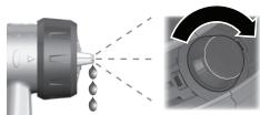
Adjustment
The air flow must be set.
-Close handle 16 to the left.
The air flow must be increased.
-Close handle 16 to the right.
Transport
Press the pedal to lock the brake. The brake is engaged in the socket 17. Thank you for the locking mechanism that holds it in the socket. There is a risk of injury.
-Place the pedal in the socket and press it until it is securely engaged.
Maintenance and service
The spray gun must be cleaned after each use to prevent clogging and ensure proper operation.
Cleaning (see section I-K)
Proper cleaning is a prerequisite for trouble-free operation of the spray gun. If the gun is not cleaned or is not cleaned well, paint residues and defects may occur.
Clean the spray gun with the appropriate solvent (thinner or water) for the paint used.
Never immerse the entire spray gun in solvent.
Never clean the openings of the nozzle or the air vents of the gun with sharp metal objects.
When cleaning, do not exceed the maximum permissible pressure.
If you have been spraying, take time to clean the gun especially carefully.
Disconnect the main air supply hose 9 from the gun so that the residual pressure can be released. - Remove the reservoir 8 and pour out the remaining paint. Rinse the reservoir with solvent (thinner or water) and wipe the gun. Shake the gun several times. Connect the main air supply and spray solvent into a waste container. Repeat the last three steps until the solvent comes out clean. Disconnect the main air supply. - Fill the reservoir 8 completely. - Make sure that the suction tube 10 of the reservoir has enough paint material left. Clean the spray gun with a cloth moistened with solvent. - Remove the air cap 3 and the air nozzle 2. - Clean the nozzle 11 and the nozzle needle with solvent.
Changing the air filter (see section L)
When the air filter becomes clogged, it must be replaced.
- Remove the air filter cap 21.
- Replace the air filter. Reinstall the air filter cap.
Disposal of used materials
Dispose of the waste material in an environmentally responsible manner.
The cleaning agent must not be allowed to enter the soil, groundwater, or open water bodies. Never dispose of cleaning agents in household drains!
Dr. Egbert Schneider Senior Vice President Engineering
Dr. Eckerhard Ströttgen Head of Product Certification

06.02.2008, Robert Bosch GmbH, Power Tools Division D-70745 Leinfelden-Echterdingen
Assembly
Pull the mains plug out of the socket before carrying out any work on the power tool.
Dr. Egbert Schneider Senior Vice President Engineering
Dr. Eckerhard Ströttgen Head of Product Certification
06.02.2008, Robert Bosch GmbH, Power Tools Division D-70745 Leinfelden-Echterdingen
Assembly
Dr. Egbert Schneider Senior Vice President Engineering
Dr. Eckerhard Ströttgen Head of Product Certification
06.02.2008, Robert Bosch GmbH, Power Tools Division D-70745 Leinfelden-Echterdingen
Assembly
Before any work on the power tool, pull the mains plug out of the socket.
General safety instructions
Dr. Egbert Schneider Senior Vice President Engineering
Dr. Eckerhard Strötgen Head of Product Certification
i.v. 107gcu
06.02.2008, Robert Bosch GmbH, Power Tools Division D-70745 Leinfelden-Echterdingen
Assembly
Before any work on the power tool, pull the plug out of the socket.
Dr. Egbert Schneider Dr. Eckerhard Ströttgen Senior Vice President Head of Product Engineering Certification
ppa. Maae i.v. Nogcu
06.02.2008, Robert Bosch GmbH, Power Tools Division D-70745 Leinfelden-Echterdingen
Storage
Before any work on the power tool, pull the plug out of the socket.
Robert Bosch GmbH, Dept. PT/ESC,
D-70745 Leinfelden-Echterdingen
Dr. Egbert Schneider
Dr. Eckerhard Strötgen
Senior Vice President
Head of Product
Engineering
Certification
06.02.2008, Robert Bosch GmbH, Power Tools Division D-70745 Leinfelden-Echterdingen
Assembly

- PFS 105E
- BOSCH
- ASSEMBLY
- GENERAL POWER TOOL SAFETY WARNINGS
- WARNING
- WORKPLACE SAFETY
- ELECTRICAL SAFETY
- PERSONAL SAFETY
- USE AND CARE OF THE POWER TOOL
- SERVICE
- SAFETY WARNINGS FOR FINE-SPRAY SYSTEMS
- FUNCTIONAL DESCRIPTION
- INTENDED USE
- NOISE/VIBRATION INFORMATION
- WEAR HEARING PROTECTION
- PRODUCT FEATURES
- SPRAY GUN
- AIR HOSE
- BASE UNIT
- DECLARATION OF CONFORMITY
- CONNECTING THE AIR HOSE
- (SEE FIGURES A1 - A2)
- OPERATION
- PREPARING FOR OPERATION
- PREPARING THE SPRAY SURFACE
- DILUTING SPRAY MATERIAL
- OR
- FILLING IN SPRAY MATERIAL (SEE FIGURES C1-C2)
- STARTING OPERATION
- SWITCHING ON
- SWITCHING OFF
- WORKING ADVICE
- SPRAYING (SEE FIGURES D-E)
- ADJUSTING THE SPRAY PATTERN (SEE FIGURE F)
- AIR CAP JET
- APPLICATION
- A
- B
- ADJUSTING THE SPRAYING CAPACITY (SEE FIGURE G)
- SPRAYING CAPACITY
- ADJUSTMENT
- ADJUSTING THE AIR FLOW (SEE FIGURE H)
- AIR FLOW
- TRANSPORT
- MAINTENANCE AND SERVICE
- MAINTENANCE AND CLEANING
- CLEANING (SEE FIGURES I-K)
- CHANGING THE AIR FILTER (SEE FIGURE L)
- MATERIAL DISPOSAL
- MAINTENANCE
- AFTER-SALES SERVICE AND CUSTOMER ASSISTANCE
- WWW.BOSCH-PT.COM
- GREAT BRITAIN
- AUSTRALIA, NEW ZEALAND AND PACIFIC ISLANDS
- DISPOSAL
- ONLY FOR EC COUNTRIES
- MONTAGE
- CONNECT THE AIR HOSE (SEE FIGURES A1-A2)
- TECHNICAL DATA
- INSTRUCTIONS FOR USE AND SAFETY
- WEAR EAR PROTECTION
- DECLARED DATA
- IIOTOL YEKAOOOU
- GREECE
- MONTAJ
- MONTAŽ
- MONTÁŽ
- GENERAL WARNING NOTICES AND SAFETY INSTRUCTIONS
- CAUTION
- SAFETY INSTRUCTIONS
- FOR THIN-LAYER
- SPREADING SYSTEMS
- OTNCAHNE YHKCNN
- NOISE VALUES DETERMINED IN ACCORDANCE WITH EN
- ILLUSTRATED COMPONENTS
- AIR CAP
- BASE BLOCK
- DILUTION OF THE MATERIAL TO BE SPRAYED
- MATERIAL TO BE SPRAYED
- RECOMMENDED DILUTION
- RABBIT CAGE MATERIAL (SEE FIG. C1-C2)
- APPLICATION INSTRUCTIONS
- SPRAYING (SEE FIG. D-E)
- ADJUSTING THE SPRAY PATTERN (SEE FIG. F)
- DO NOT ACTIVATE THE TRIGGER 9 WHEN ADJUSTING THE AIR CAP
- FOR VERTICAL WORK
- ADJUSTING THE AMOUNT OF SPRAYED MATERIAL (SEE FIG. G)
- AMOUNT OF SPRAYED MATERIAL
- AIR CONSUMPTION
- BELARUS
- UTILIZATION
- TOIBKO DAA CTPAH-UAHEOB EC
- ARAIBHI IIOIPEEKEHHA AIAELEKTPOPPHAADIB
- TONEPEDXEHHA IPOUHTATE IPABNAA
- EPIRATTE BCI IPABNLA 3 TEXHIKN 6E3NEKN I BKA3IBKN HA MAJ6YTHC
- TICTOAET-P03NIIOBAU
- TOBITPHM ⅢAAHR
- BA3OBN BY3OA
- ADJUST THE VISCOSITY OF THE DILUTED MATERIAL (SEE FIG. G)
- AMOUNT OF PAINT
- TRANSPORTATION
- INSERTING THE AIR NOZZLE (SEE FIGURES A1-A2)
- NEVER PRESS THE TRIGGER 9 WHILE ADJUSTING THE AIR MEMBRANE
- ADJUSTING THE AMOUNT OF SPRAY MIST (SEE FIGURE G)
- AMOUNT OF MIST
- ADJUSTING THE AIR VALVE (SEE FIGURE H)
- BULGARIAN
- CLEANING (SEE SECTION I-K)
- CHANGING THE AIR FILTER (SEE SECTION L)
- DISPOSAL OF USED MATERIALS
- GENERAL SAFETY INSTRUCTIONS
- STORAGE
Brand : BOSCH
Model : PFS 105E
Category : Paint gun