
Mini Bordeaux - Range hood Thermex - Free user manual and instructions
Find the device manual for free Mini Bordeaux Thermex in PDF.


| Product Type | Built-in range hood |
| Model | Mini Bordeaux |
| Brand | Thermex |
| Mounting Type | Wall-mounted under cabinet |
| Width | 60 cm (estimated) |
| Height | Adjustable, approx. 50-70 cm above cooktop |
| Weight | Approx. 8 kg (estimated) |
| Power Supply | 230 V ~ 50 Hz, 10 A |
| Motor Type | Internal or external motor option |
| Extraction Mode | Ducted (air exhaust) or recirculation |
| Exhaust Outlet | Reversible: top or rear |
| Controls | Mechanical switches (not detailed) |
| Lighting | LED (not specified, typical) |
| Grease Filter Type | Metal mesh, washable |
| Recirculation Filter | Optional carbon filter, replaceable |
| Minimum Distance to Gas Stove | 65 cm (EN 60335-2-31) |
| Recommended Distance to Cooktop | 50-70 cm |
| Noise Level | Not specified, typical around 55 dB |
| Energy Efficiency | Not specified |
| Cleaning | Daily wipe; grease filter every 1-3 weeks; carbon filter replace 2-4 times/year |
| Safety Features | Disconnect power before cleaning; earth connection required |
| Warranty | Standard Thermex warranty (keep sales receipt) |
Frequently Asked Questions - Mini Bordeaux Thermex
User questions about Mini Bordeaux Thermex
0 question about this device. Answer the ones you know or ask your own.
Ask a new question about this device
Download the instructions for your Range hood in PDF format for free! Find your manual Mini Bordeaux - Thermex and take your electronic device back in hand. On this page are published all the documents necessary for the use of your device. Mini Bordeaux by Thermex.
USER MANUAL Mini Bordeaux Thermex
natural_image
Three symbolic icons: a person reading, a book with gears and a box, and a rectangular block with double-headed arrows indicating measurement or dimension (no text or symbols present)THERMEX SCANDINAVIA A/S

www.thermex.dk

THERMEX SCANDINAVIA AS

www.thermex.no

THERMEX SCANDINAVIA AB

www.thermex.se

THERMEX SCANDINAVIA S.L.U.

www.thermex.es

THERMEX SCANDINAVIA A/S

www.thermex.fi


natural_image
Simple line drawing of an open box with a curved arrow pointing upward (no text or symbols)
natural_image
Simple line drawing of an open book with gears and a block, no text or symbols present.× 1
natural_image
Simple line drawing of a block on a platform with two wavy lines below (no text or symbols)x1x1
x 4
x 4
natural_image
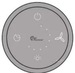
Circular diagram with icons including power sources, fan, and sun symbols (no text or labels)x 1
natural_image
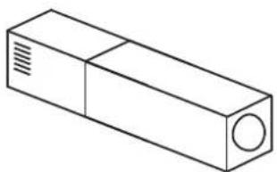
Isometric line drawing of a rectangular electronic component with a circular end and ventilation slots (no text or symbols)
x 1
x 2
INDHOLD
| Dansk | 6 |
| Norsk | 16 |
| Svenska | 26 |
| Suomi | 36 |
| Español | 46 |
| English | 56 |
6 THERMEX Mini Perpignan & Mini Bordeaux M 540231481222122020
INDHOLD
Generel adversel 7
Montering 8
Elinstallation 12
Eldiagram 13
natural_image
Diagram showing a room with a wall, a circular object, and a small rectangular area with two circles (no text or symbols)natural_image
Diagram of a laptop with an open screen and a blue arrow indicating motion (no text or symbols)natural_image
Diagram of a laptop with an open screen and a blue arrow pointing to the screen area (no text or symbols present)natural_image
Diagram showing a cylindrical object being placed on a base with an inset magnified view of its internal structure (no text or symbols)natural_image
Architectural diagram of a double door mounted on a shelf, showing structural details without any text or symbols.natural_image
Diagram of a mechanical or structural assembly with an upward arrow and shaded cross-section (no text or symbols)natural_image
Technical diagram of a 3D mechanical assembly with a magnified inset showing internal components (no text or symbols)natural_image
Pure technical diagram of a mechanical assembly with no text, numbers, or symbolsnatural_image
Diagram of a mechanical or architectural component with a blue upward arrow and hatched base, no visible text or symbols.natural_image
Technical illustration of a 3D mechanical assembly with a magnified inset showing a cube and a pencil (no text or symbols)natural_image
Mechanical component diagram showing a rotating arm with directional arrows and a 90° angle label (no readable text or symbols)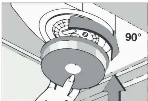
natural_image
Illustration of a hand holding a circular mechanical component with a 90-degree angle marker (no text or symbols on the diagram itself)VENDBART AFTRÆK
natural_image
Diagram of a screwdriver with a magnified view showing a circular component and wire, no text or symbols present.natural_image
Technical line drawing of a mechanical component with two views (top and side), no text or symbols present.Løft motoren ud.
5
natural_image
Technical line drawing of a cabinet with ventilation grilles and a side-view inset showing internal fan structure (no text or symbols)natural_image
Diagram of a cable being inserted into a circular component on a base plate, with a magnified inset showing the x2 tool (no text or symbols present)flowchart
graph TD
    A["230V"] --> B[" fan with fan icon"]
    B --> C[" External Motor Quick Start "]
    D["12"] --> E[" fan with fan icon"]
    E --> C
ELDIAGRAM
RENG∅RING OG VEDLIGEHOLD
flowchart
graph LR
    A["Device with grid pattern"] --> B["Switch"]
    B --> C["Mobile Device"]
SERVICE
natural_image
Diagram showing a room with a patterned wall, a circular disc, and a small rectangular object on the floor (no text or symbols)natural_image
Diagram of a laptop with an open screen and a blue arrow indicating motion (no text or symbols)natural_image
Diagram of a laptop with an open screen and a blue arrow pointing to the screen area (no text or symbols)natural_image
Diagram showing a cylindrical object being placed on a base with an inset magnified view of its internal structure (no text or symbols)Monter avtrekket på viften.
natural_image
Architectural diagram of a double door mounted on a wall, showing structural components and floor level (no text or labels)Skru braketten fast til veggen.
4
natural_image
Diagram of a mechanical or structural assembly with a blue upward arrow and shaded cross-section (no text or symbols)Sett kanalen på viften. Skyv kanalens overdel oppover, og fest den i
5
natural_image
Technical line drawing of a 3D mechanical assembly with an inset showing a cross-sectional view (no text or symbols)braketten med de to selvborende skruene.
INSTALLASJON AV KANAL NÅR VIFTEN BRUKES TIL Å RESIRKULERE LUFTEN
natural_image
Pure technical diagram showing a mechanical assembly with no text, numbers, or symbolsSkru braketten og dekkplaten fast til veggen.
4
natural_image
Diagram of a mechanical assembly with an upward arrow and shaded section, no text or symbols presentSett kanalen på viften.
natural_image
Technical diagram showing a 3D mechanical assembly with a magnified inset of a cube and a pencil icon labeled 'x2' (no text or symbols on the main diagram)Skyv kanalens overdel oppover, og fest den i braketten med de to selvborende skruene.
natural_image
Mechanical component diagram showing a rotating arm with a 90-degree angle indicator (no text or symbols on the diagram itself)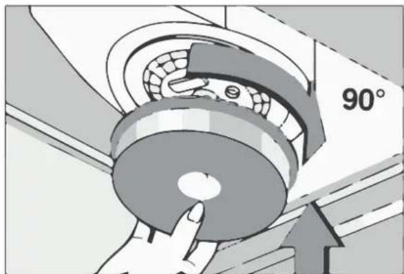
natural_image
Illustration of a hand pressing down on a mechanical component with a 90° angle label (no text or symbols beyond the angle marker)VENDBART AVTREKK
natural_image
Diagram of a screwdriver with a magnified view showing a circular component and wire, no text or symbols present.Løsne strekkavlasteren fra ledningen.
4
natural_image
Technical line drawing of a mechanical component with two views (top and side), no text or symbols present.natural_image
Technical line drawing of a 3D box with ventilation slots and a side-view inset showing a circular fan (no text or symbols)natural_image
Diagram of a cable being inserted into a circular component on a base plate, with a magnified inset showing the x2 tool (no text or symbols present)flowchart
graph TD
    A["230V"] --> B[" fan with fan icon"]
    B --> C[" External Motor Quick Start "]
    D["12"] --> E[" fan with fan icon"]
    E --> C
ELDIAGRAM
VEDLIKEHOLD OG RENGJ∅RING
natural_image
Diagram showing a room with a framed picture and a circular object, no text or symbols presentnatural_image
Diagram of a laptop with an open screen and a blue arrow indicating motion (no text or symbols)natural_image
Diagram of a laptop with an open screen and a blue arrow pointing to the screen area (no text or symbols)natural_image
Diagram showing a cylindrical object being placed on a base with an inset magnified view of its internal structure (no text or symbols)natural_image
Architectural line drawing of a double door mounted on a wall, showing structural components and floor level (no text or symbols)natural_image
Diagram of a mechanical or architectural component with an upward arrow and shaded cross-section (no text or symbols)natural_image
Technical line drawing of a 3D mechanical assembly with an inset showing a cross-sectional view of a rectangular component (no text or symbols present)natural_image
Pure technical diagram of a mechanical assembly with no text, numbers, or symbolsnatural_image
Diagram of a mechanical or architectural component with a blue upward arrow and hatched base, no text or symbols present.natural_image
Technical diagram showing a 3D mechanical assembly with a magnified inset of a cube and a pencil, no text or symbols present.natural_image
Mechanical component diagram showing a 90-degree angle with directional arrows (no text or symbols)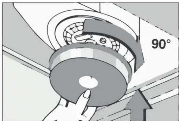
natural_image
Illustration of a hand pressing down on a mechanical component with a 90° angle label (no text or symbols beyond the angle marker)VÄNDBART UTSUG
natural_image
Diagram of a screwdriver with a magnified view showing a circular component and wire, no text or symbols present.natural_image
Technical line drawing of a mechanical component with two views (top and side), no text or symbols present.natural_image
Technical line drawing of a rectangular box with side panels and a side-view inset showing a circular fan or vent (no text or symbols)natural_image
Diagram of a screwdriver with a magnified view showing a circular component and wire, no text or symbols present.flowchart
graph TD
    A["230V power source"] --> B[" fan installation"]
    B --> C[" External motor quick start"]
    C --> D[" circuit diagram with fan icon"]
ELDIAGRAM
UNDERHÄLL OCH RENGÖRING
BYTE AV RECIRKULATIONSFILTER
flowchart
graph LR
    A["Device with grid pattern"] -->|✓| B["Mobile Device"]
SERVICE
natural_image
Diagram showing a room with a patterned wall, a circular disc, and a small rectangular object with two circles (no text or symbols)natural_image
Diagram of a laptop with an open screen and a blue arrow indicating motion (no text or symbols)natural_image
Diagram of a laptop with an open screen and a blue arrow pointing to the screen area (no text or symbols)natural_image
Diagram showing a cylindrical object being placed on a base with an inset magnified view of its internal structure (no text or symbols)natural_image
Architectural diagram of a double door mounted on a wall, showing structural components and floor level (no text or symbols)natural_image
Diagram of a mechanical or structural assembly with an upward arrow and shaded cross-section (no text or symbols)natural_image
Technical line drawing of a 3D mechanical assembly with an inset showing a cross-sectional view (no text or symbols)natural_image
Pure technical diagram showing a mechanical assembly with no text, numbers, or symbolsnatural_image
Diagram of a mechanical or architectural component with a blue upward arrow and hatched base, no visible text or symbols.natural_image
Technical illustration of a 3D mechanical assembly with a magnified inset showing a cube and a pencil (no text or symbols)natural_image
Mechanical component diagram showing a rotating arm with directional arrows and a 90° angle label (no readable text or symbols)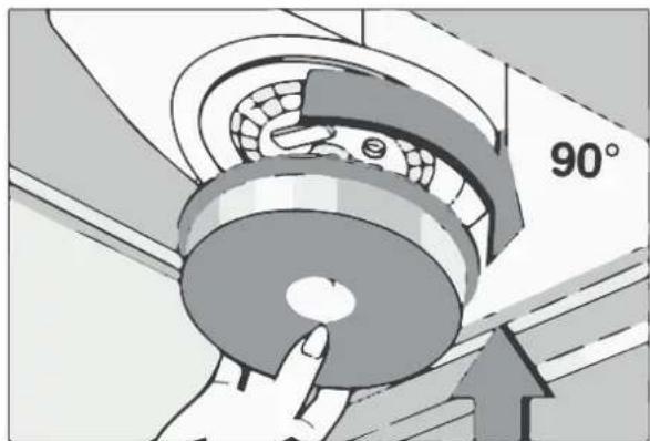
natural_image
Illustration of a hand pressing down on a mechanical component with a 90° angle label (no text or symbols beyond the angle marker)KÄÄNNETTÄVÄ POISTOAUKKÖ
natural_image
Diagram of a screwdriver with a magnified view showing a circular component and wire, no text or symbols present.natural_image
Technical line drawing of a mechanical component with two views (top and side), no text or symbols present.natural_image
Technical line drawing of a rectangular box with side panels and a side-view inset showing a circular fan or vent (no text or symbols)natural_image
Diagram of a screwdriver with a wire and probe inserted into a circular component, mounted on a base plate (no text or symbols)flowchart
graph TD
    A["230V"] --> B[" fan with fan icon"]
    B --> C[" External Motor Quick Start "]
    D["12"] --> E[" fan with fan icon"]
    E --> C
KYTKENTÄKAAVIOV
HUOLTO JA PUHDISTUS
natural_image
Simple line drawing of a room with a wall, a circular inset showing a ring and a small object, no text or symbols present.natural_image
Diagram of a laptop with an open screen and a blue arrow indicating motion (no text or symbols)natural_image
Diagram of a laptop with an open screen and a blue arrow pointing to the screen area (no text or symbols)natural_image
Diagram showing a cylindrical object being inserted into a base, with an inset magnified view of the component (no text or symbols)natural_image
Technical line drawing of a ceiling-mounted cabinet or lift system mounted on a tiled wall (no text or symbols)natural_image
Diagram of a mechanical or architectural component with an upward arrow and shaded cross-section (no text or symbols)natural_image
Technical line drawing of a 3D mechanical assembly with an inset showing a cross-sectional view of a rectangular component (no text or symbols present)natural_image
Pure technical diagram of a mechanical assembly with no text, numbers, or symbolsnatural_image
Diagram of a mechanical or architectural component with a blue upward arrow and shaded cross-section (no text or symbols)natural_image
Technical diagram showing a 3D mechanical assembly with a magnified inset of a cube and a pencil icon labeled 'x2' (no text or symbols on the main diagram)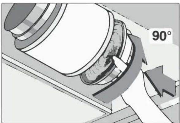
natural_image
Mechanical component diagram showing a rotating arm with a 90-degree angle indicator (no text or symbols on the diagram itself)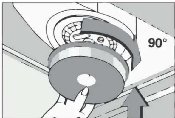
natural_image
Illustration of a hand pressing down on a mechanical component with a 90° angle label (no text or symbols beyond the angle marker)SALIDA GIRABLE
natural_image
Diagram showing a screwdriver with a magnified view of a circular component connected to a wire, no text or symbols present.natural_image
Technical line drawing of a cabinet with two circular components and a fan-shaped housing (no text or symbols)natural_image
Technical line drawing of a cabinet with ventilation grilles and a side-view inset showing fan structure (no text or symbols)natural_image
Diagram of a screwdriver with a wire and magnified view showing a circular component (no text or symbols)flowchart
graph TD
    A["230V"] --> B[" fan with fan icon"]
    B --> C[" External Motor Quick Start "]
    C --> D[" fan with fan icon"]
    D --> E[" Final motor output"]
DIAGRAM DE TABLERO
MANTENIMIENTO Y LIMPIEZA
flowchart
graph LR
    A["Device with grid pattern"] -->|✓| B["Mobile Phone"]
SERVICIO
Electrical installation 62
Board diagram 63
Maintenance and cleaning 64
Service 65
WARNINGS
- The range hood is designed and manufactured according to DS/EN 60335-1.
- This range hood is only for use in private house holdings, if used for other purposes the warranty will be repealed.
- Installation must be performed by a skilled electrician in accordance with the specifications given by Thermex Scandinavia A/S (Thermex) and legislation in force.
- Thermex disclaims all responsibility in regards to damages caused by wrong installation, mounting or use.
BEFORE MOUNTING/COMMISSIONING
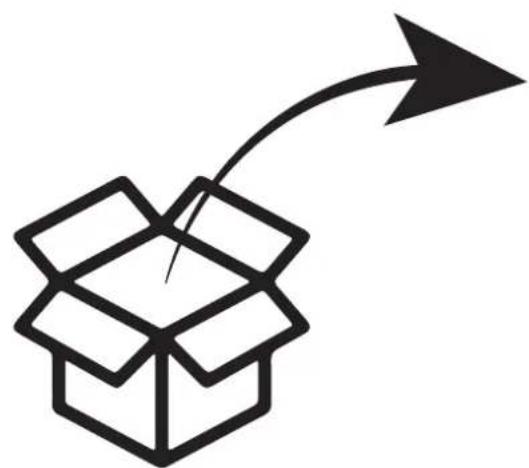
- Inspect the range hood for transport damages, flaws and defects immediately after the receipt.
- Transport damages must be filed to the haulage contractor and Thermex immediately after the receipt.
- Flaws and defects must be filed to Thermex within 8 days the receipt, and not later than mounting/commissioning.
MOUNTING
- The range hood is intended for working at 230 Volt ±10%\~50 HZ in referring to EN 50160.
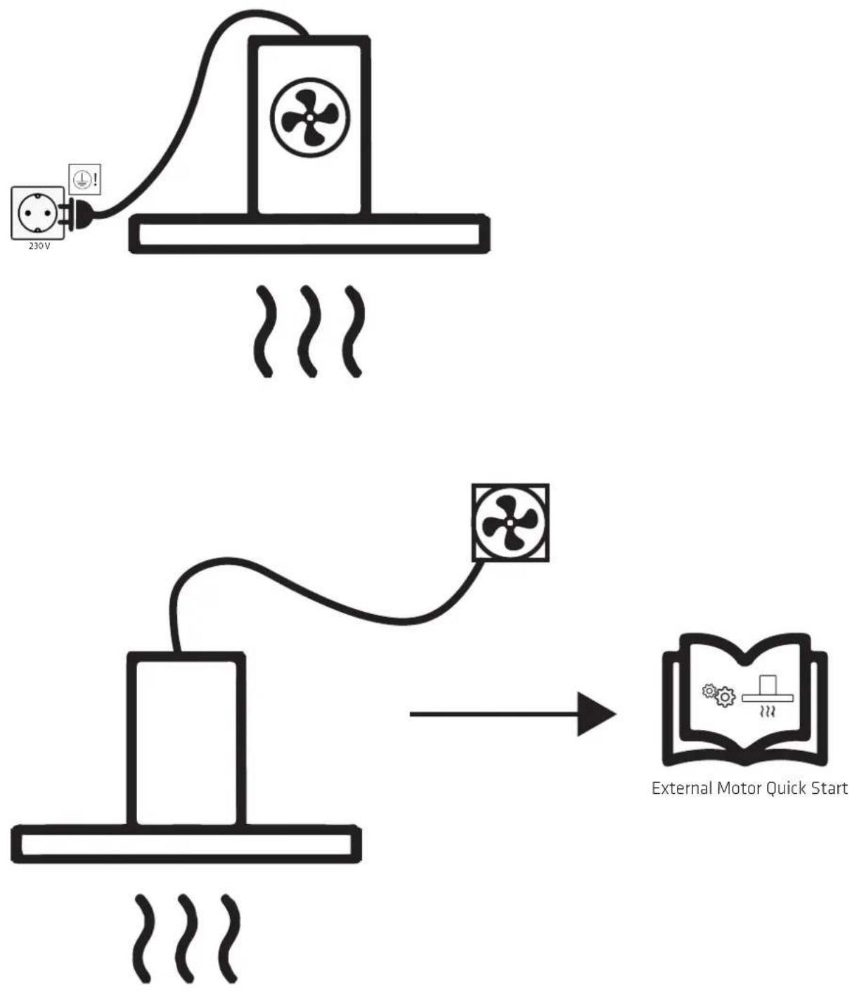
- Connect the hood with the attached plug. NOTE: The hood MUST have earth if the plug has an earth connection.
- For models with external motor applies that NOT to use common zero by installing the hood and engine, as this will affect the control.
- It MUST be ensured that the motor can be used with the selected range hood when using an external motor from another supplier. Otherwise the warranty no longer apply.
- Do not plug in the range hood until the mounting is complete.
-
The air must not be discharged from the hood into a pipe used for extraction from devices using gas or other fuels. Such devices must have a separate vent.
• The national legislation on air emissions must be observed. -
Always use the original dimension of the vent. By reducing the dimension of the vent, the performance will be reduced and the sound level will be increased.
- The vent to the open air, must be as short as possible in order to get the greatest possible capacity of the range hood.
- The number of bends on the vent ought to be minimised, to gain the greatest possible capacity of the range hood.
- Thermex recommends to always use sound and condensation insulated vent hose at the carrying through in unheated spaces.
- Thermex recommends that there is used for a muffler to minimize the noise level when using flexible hose.
- Using the flexible hose must always ensure that this is fully extended to minimize air resistance and thereby achieve maximum absorbency.
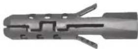
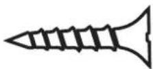
- Different materials takes different rawlplugs and screws. Use rawlplugs and screws intended for the material the range hood is to be mounted in.
- If the instructions for the installation of screws and fittings are not followed, it may result in electrical shock.
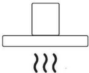
- The minimum distance to gas stoves from the burner's edge to the underside of the hood MUST be minimum 65 cm in accordance with EN 60335-2-31.
- Thermex recommends that the space between the lower edge of the range hood and cooker is between 50 cm and 70 cm, valid for all cabinet range hoods, islands and wall mounted range hoods.
• Always control the stated minimum distance between cooker and range hood in the manual for the cooker. If the manual for the cooker states a greater distance than what Thermex recommends the manual for the cooker MUST be followed. - Thermex recommends that the space between cooker and range hood does not exceed 3 meters for range hoods integrated in the ceiling
INSTALLATION
The range hood is available either with an internal motor or for installation with an external motor.
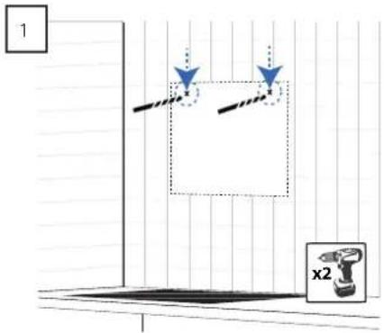
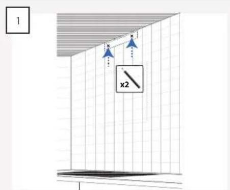
Measure out and mark the two "keyholes" on the wall. NOTE: For a rear-facing exhaust outlet, the holes are marked out in relation to the exhaust outlet's position on wall
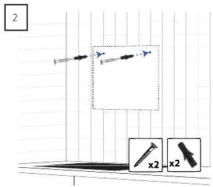
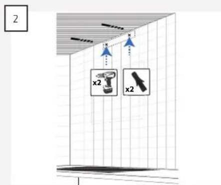
Ensure that the rawlplugs and screws are suitable for the wall material in question and insert them into the pre-drilled holes.
natural_image
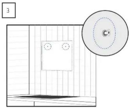
Diagram showing a room with a wall, a circular inset with dashed lines and a central circular object, and a small dark object on the floor (no text or symbols)NOTE: The screws must not be screwed in further than the hood can be installed.
natural_image
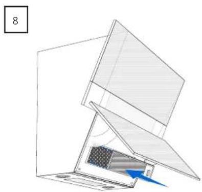
Diagram of a laptop with an open screen and a blue arrow indicating motion (no text or symbols)Hang the hood on the screws. Open the glass door and remove the filter.
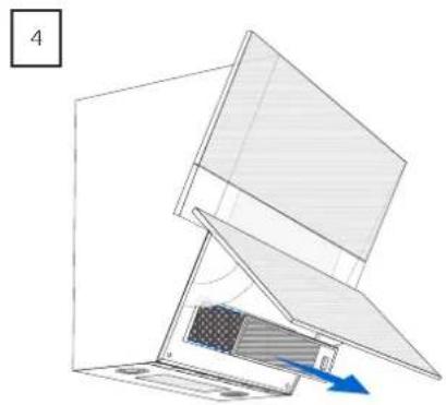
Mark the position of the two lock-holes on the wall and then remove the hood from the wall once again.
Pre-drill the holes and insert the rawlplugs.
Re-hang the hood.
NOTE: For a rear-facing exhaust outlet, the exhaust outlet should be installed on the hood in this step.
natural_image
Diagram of a laptop with an open screen and a blue arrow pointing to the screen area (no text or symbols)Reinstal the filter in the hood and close the glass door.
natural_image
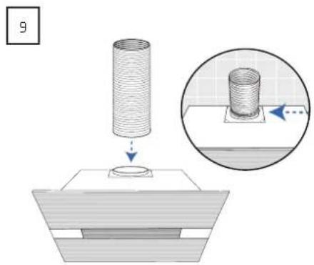
Diagram showing a cylindrical object being placed on a base with an inset magnified view of its internal structure (no text or symbols)Install the exhaust outlet on the hood.
NOTE: This only applies when venting into open air and with the exhaust outlet facing upwards.
INSTALLING THE DUCT
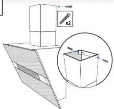
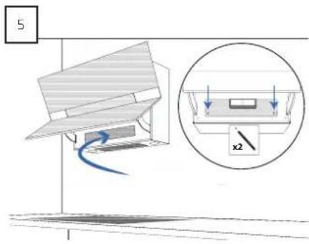
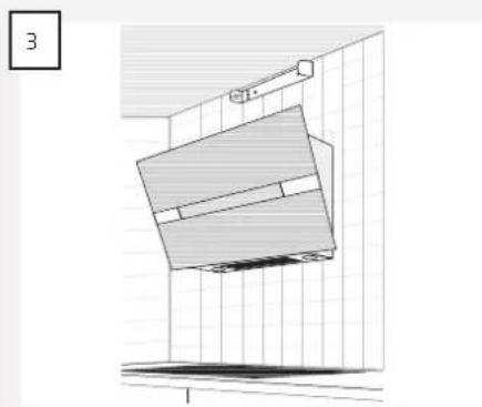
Measure the placement of the bracket and mark the position of the holes on the wall.
NOTE: The bracket must be positioned so that it matches the holes in the duct.
Pre-drill the holes and insert the rawlplugs.
natural_image
Architectural diagram of a double door mounted on a wall, showing structural components and floor level (no text or labels)Screw the bracket onto the wall.
natural_image
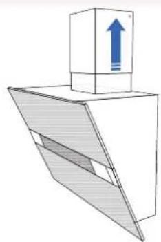
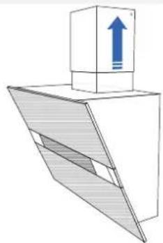
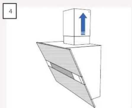
Diagram of a mechanical or electrical component with a blue upward arrow and shaded internal section, no text or symbols present.Place the duct on the hood.
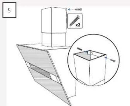
Push the topmost section of the duct upwards and attach it to the bracket with the two self-tapping screws.
INSTALLING THE DUCT WHEN THE HOOD IS TO BE USED FOR RECIRCULATION
If the hood is going to be used for recirculation, the cover panel must be installed up to the ceiling to cover the duct.
The duct is therefore installed as follows:
1
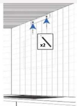
Measure the placement of the bracket and mark the position of the holes on the wall.
NOTE: The bracket must be positioned so that it matches the holes in the duct.
2
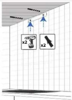
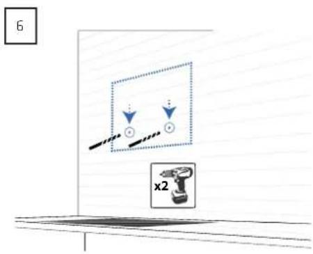
Pre-drill the holes and insert the rawlplugs.
3
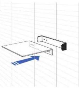
natural_image
Pure technical diagram of a mechanical assembly with no text, numbers, or symbolsScrew the bracket and cover panel onto the wall.
4
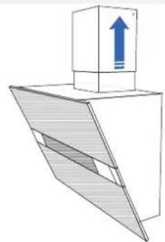
natural_image
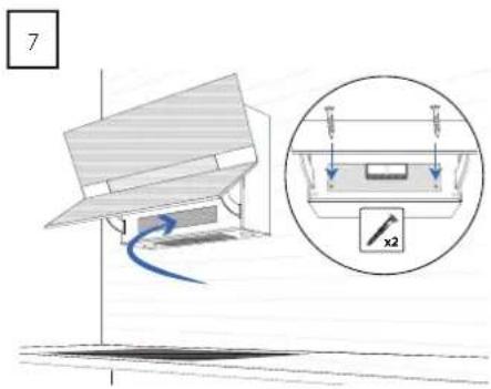
Diagram of a mechanical or architectural component with a blue upward arrow and hatched base, no visible text or symbols.Place the duct on the hood. Push the topmost section of the duct upwards
5
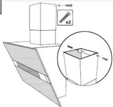
natural_image
Technical illustration of a 3D mechanical assembly with a magnified inset showing a cube and a small component labeled 'x2' (no text or symbols present)and attach it to the bracket with the two self-tapping screws.

natural_image
Mechanical component diagram showing a rotating arm with directional arrows and a 90° angle label (no readable text or symbols)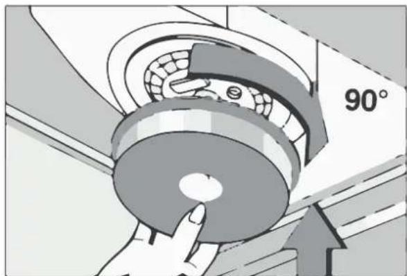
natural_image
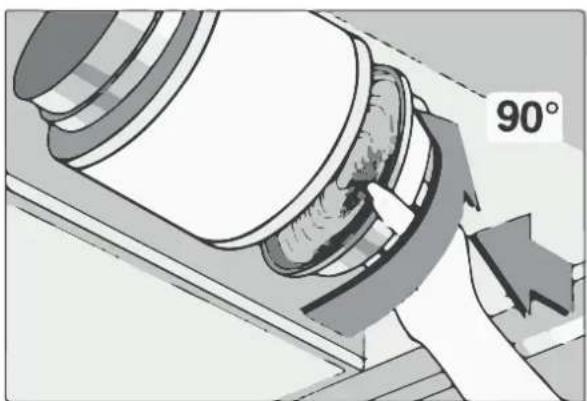
Illustration of a hand pressing down on a mechanical component with a 90° angle label (no text or symbols beyond the angle marker)EVERSIBLE EXHAUST OUTLET
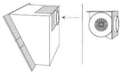
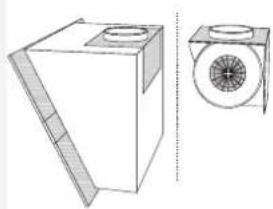
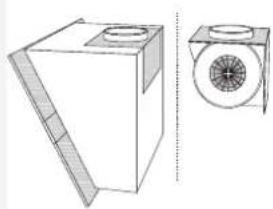
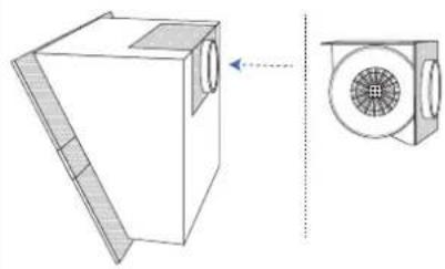
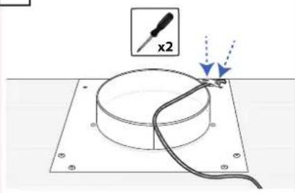
The exhaust outlet on the range hood can be reversed so that the exhaust outlet faces towards the rear.
1
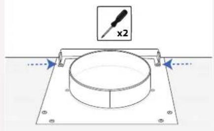
Screw the bracket of the planet on the hood.
2
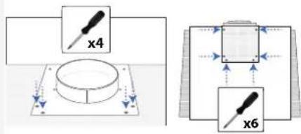
Unscrew the screws holding the panel onto the hood.
NOTE: Make sure not to unscrew the screws holding the motor to the panel.
3
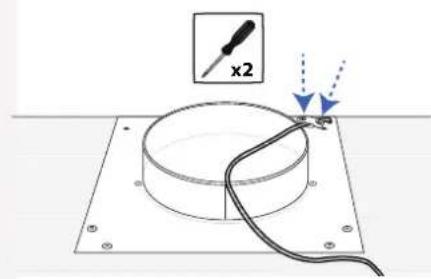
natural_image
Diagram of a screwdriver with a magnified view showing a circular component and wire, no text or symbols present.Remove the strain relief on the electrical cable.
4
natural_image
Technical line drawing of a mechanical component with two views (top and side), no text or symbols present.Lift out the motor and remove its plug.
5
natural_image
Technical line drawing of a 3D box with ventilation slots and a side-view inset showing a circular fan (no text or symbols)Place the motor on the hood with the exhaust outlet facing backwards.
6
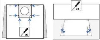
Screw the panel with the motor onto the hood.
7
natural_image
Diagram of a screwdriver with a magnified view showing a circular component and wire, no text or symbols present.Place the strain relief back on the cable.
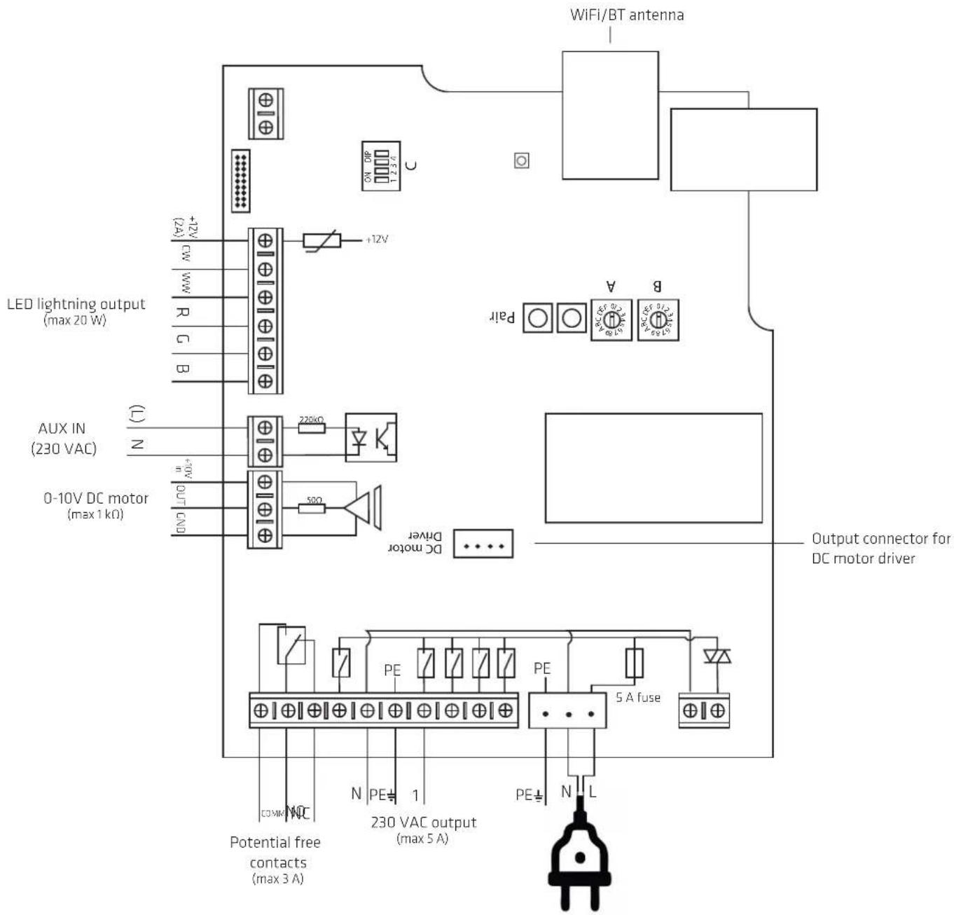
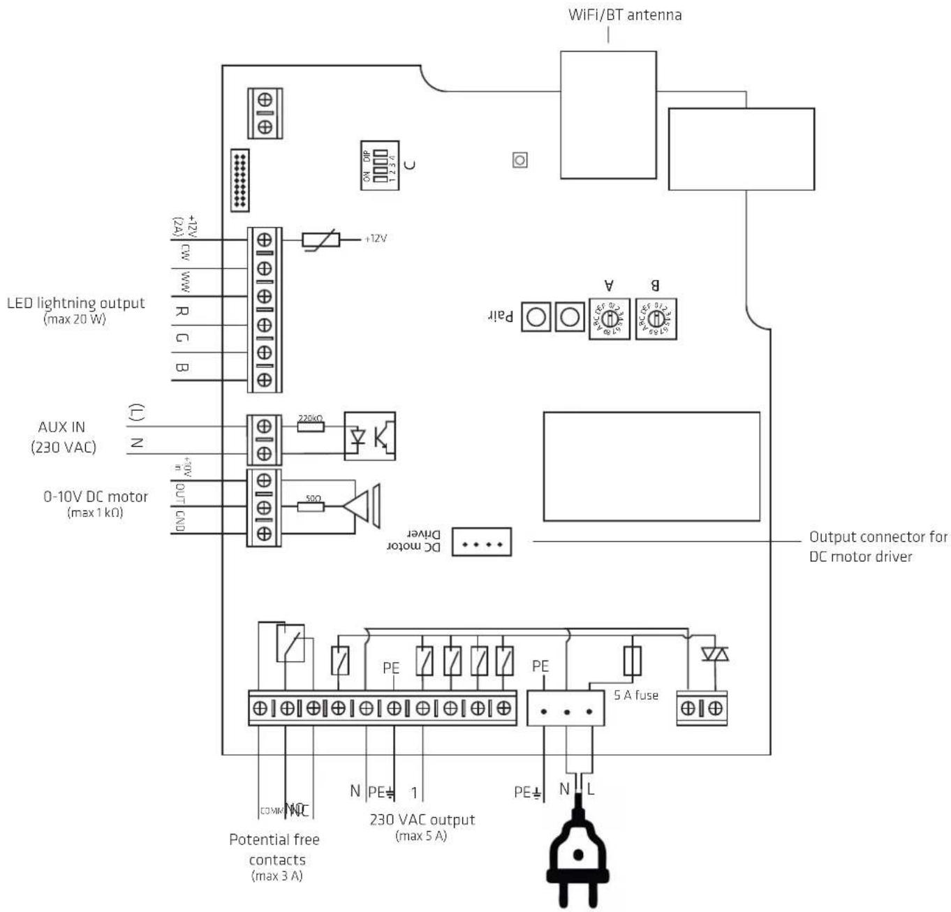
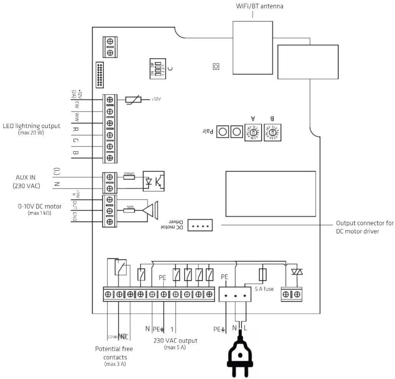
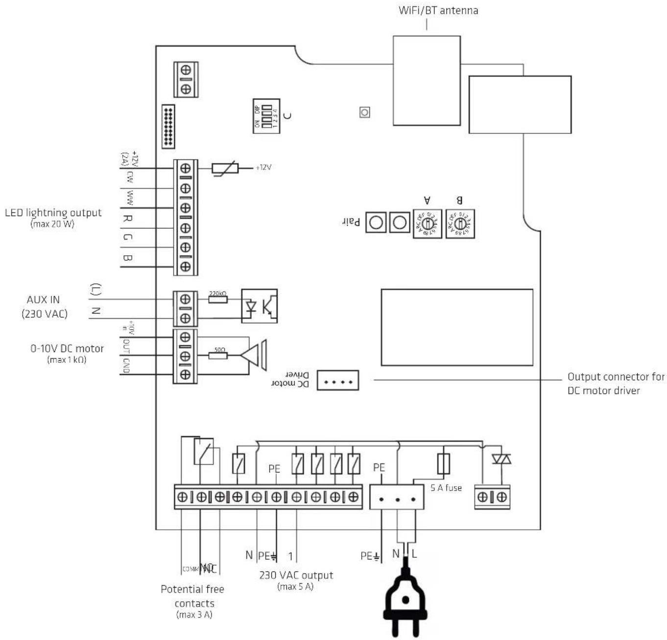
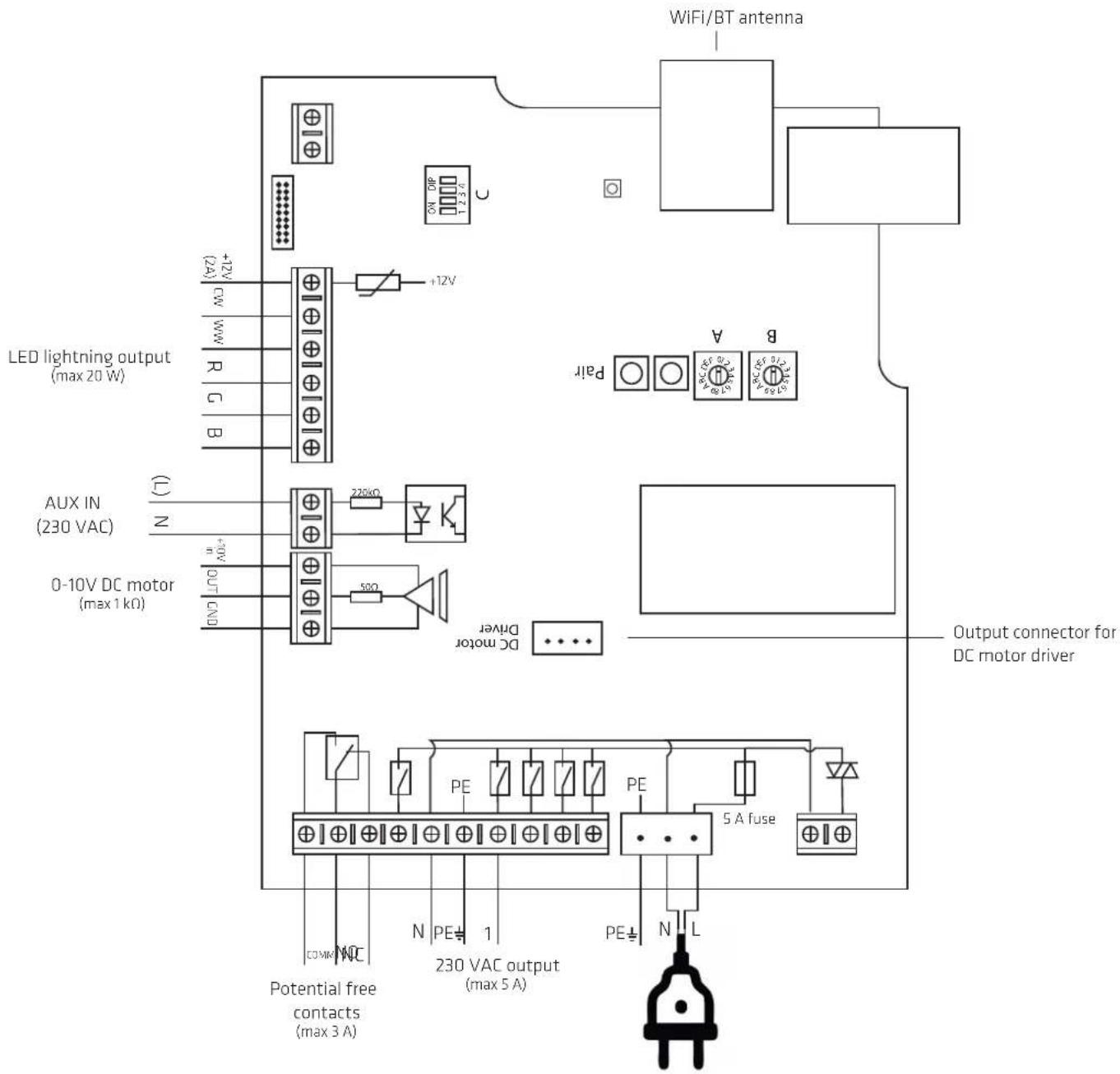
ELECTRICAL INSTALLATION
flowchart
graph TD
    A["230V"] --> B[" fan with fan icon"]
    B --> C[" External Motor Quick Start "]
    D["12"] --> E[" fan with fan icon"]
    E --> C
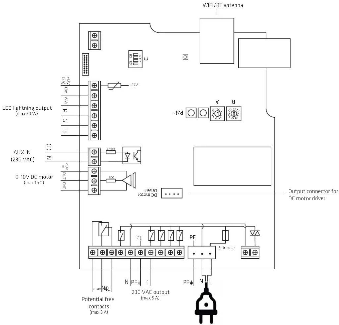
BOARD DIAGRAM
MAINTENANCE AND CLEANING
• Always disconnect power before cleaning.
- The hood must be cleaned regularly to ensure optimal operation and long service life.
- Grease and dust debris are collected in the filter and may risk igniting with insufficient cleaning.
- The hood should be cleaned inside and out frequently to avoid grease stains on walls or other surfaces.
DAILY CLEANING
- For cupboard-integrated, free-hanging and wall-mounted hoods. Thermex recommends that the grease filter be wiped with a damp cloth after each cooking session. It requires very little effort every day to keep your cooker hood clean and effective.
• Steel surfaces are cleaned with a damp cloth with detergent and treated with 3M Polish.
• Lacquered surfaces should be cleaned with a damp cloth with detergent/washing-up liquid. Never use abrasives.
CLEANING THE GREASE FILTERS
Grease filters should be cleaned as needed. Thermex recommends as a minimum that the filter is cleaned at the following intervals, depending on the fat used for frying:
• Frying margarine - filter cleaned every 3 weeks
• Liquid margarine - filter cleaned every 2 weeks
• Oil - filter cleaned once per week
- Deep fat frying - filter cleaned 2-3 times per week
The grease filters are cleaned in the following way:
- Open the glass door
- Remove the grease filter behind the glass plate and the filter in the base by pulling on the filter-locking mechanism to loosen the filter from the hood.
- Place the filters in warm soapy water and clean if necessary with a soft brush.
- Rinse with warm water.
- Leave the filters to dry on a dishcloth or similar.
- Repeat the process if necessary.
- Re-attach the filters..
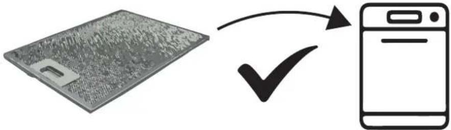
The filters can also be washed in the dishwasher, although please note that machine washing can result in discolouration of the filters. Discolouration of the filters does not affect performance.
REPLACING THE RECIRCULATION FILTERS
If recirculation filters are used, these cannot be washed, but must be replaced when needed. Thermex recommends that the recirculation filters are replaced at least 2-4 times per year.
flowchart
graph LR
    A["Device with grid pattern"] -->|✓| B["Mobile Phone"]
SERVICE
Before reporting service on your Thermex range hood, it is important that you read the installation and/or user instructions carefully. It ensures that Thermex can provide you the best possible assistance.
Service department at Thermex can be contacted in preparation to:
- Technical support for installation and installation of your range hood.
- Clarification of functionalities in your hood.
• Service Request during the warranty on your hood
Before a service request during the warranty always try to disconnect the power to the hood for about 5 min. Then plug the power back on to see if the problem is corrected.
If the problem is not corrected, disconnect the power supply to the hood for one hour. If the hood is still not functioning properly, and the troubleshooting charts are reviewed, contact the service department.
NOTE: For inquiries within the warranty, you will be asked for proof of your purchase in the form of a sales receipt. Therefore, always store your sales receipt
Before the request for service within the warranty, it is important to have all the necessary information ready:
- Error Description
- Model
- The type and serial number of the hood (on the chassis plate)
• Information of purchase
MILJ∅HENSYN
EMBALLAGE
SKROTNING AF PRODUKTET

The packaging must be disposed of in accordance with local regulations on waste management.
SCRAPPING OF THE PRODUCT

The symbol _1 on the product or accompanying documentation indicates that this product may not be disposed of as household waste but must be delivered to the nearest collection center for the recycling of electrical and electronic equipment.
THERMEX SCandinaVia a/S
- INDHOLD
- ELDIAGRAM
- RENG∅RING OG VEDLIGEHOLD
- SERVICE
- VEDLIKEHOLD OG RENGJ∅RING
- UNDERHÄLL OCH RENGÖRING
- BYTE AV RECIRKULATIONSFILTER
- KYTKENTÄKAAVIOV
- HUOLTO JA PUHDISTUS
- DIAGRAM DE TABLERO
- MANTENIMIENTO Y LIMPIEZA
- SERVICIO
- WARNINGS
- BEFORE MOUNTING/COMMISSIONING
- MOUNTING
- INSTALLATION
- EVERSIBLE EXHAUST OUTLET
- BOARD DIAGRAM
- MAINTENANCE AND CLEANING
- DAILY CLEANING
- CLEANING THE GREASE FILTERS
- REPLACING THE RECIRCULATION FILTERS
- MILJ∅HENSYN
- THERMEX SCandinaVia a/S
Brand : Thermex
Model : Mini Bordeaux
Category : Range hood