
46830 - Battery charger PROLINE - Free user manual and instructions
Find the device manual for free 46830 PROLINE in PDF.


| Product Type | Battery Charger |
| Brand | Proline |
| Model | 46830 |
| Input Voltage | 220-240 V, 50-60 Hz, 0.5 A |
| Efficiency | ≈ 85% |
| Max Power | 35 W |
| Charging Voltage | Variable |
| Charging Current | 2 A (12 V) or 1 A (12 V) selectable |
| Battery Types | Lead-acid, GEL, MF, CA, EFB, AGM |
| Battery Capacity | 2-60 Ah (12 V) |
| Low Battery Detection | > 3 V |
| Return Current Discharge | < 5 mA |
| Ambient Temperature | 0°C to +40°C |
| Charging Steps | 8-step cycle (Diagnostics, Desulphation, Analysis, Initial Charge, Bulk Charge, Absorption, Analysis, Stabilization) |
| Protection Class | IP54 |
| Cooling | Natural convection |
| Dimensions (L × H) | 15.5 × 4 cm |
| Weight | 400 g |
| Fuse | Replaceable, in red cable; replace only with identical amperage |
| Cleaning | Use soft, damp cloth with mild detergent while disconnected |
| Maintenance | No maintenance required |
| Mounting | 4 screw openings for wall or bench mounting |
| Charging Modes | 12V 2A Standard, 12V 2A Cold/AGM, 12V 1A Standard, 12V 1A Cold/AGM |
| Indicators | 4-level charge LEDs (25%, 50%, 75%, 100%) and error LED |
| Safety Features | Reverse polarity protection, short circuit protection, overheat protection, spark-proof |
Frequently Asked Questions - 46830 PROLINE
User questions about 46830 PROLINE
0 question about this device. Answer the ones you know or ask your own.
Ask a new question about this device
Download the instructions for your Battery charger in PDF format for free! Find your manual 46830 - PROLINE and take your electronic device back in hand. On this page are published all the documents necessary for the use of your device. 46830 by PROLINE.
USER MANUAL 46830 PROLINE
Keep the manual for future use.

WARNING! Read all safety warnings marked with the symbol ⚠️ and safety tips.
INFORMATION ON USE SAFETY
- Do not leave children near the charger unattended!
Children cannot assess possible hazards related to contact with electrical devices.
-This device can be used by children above 8 years of age and by people with limited physical, sensory or mental capacities or those not having appropriate experience and/or knowledge only under the supervision of a responsible person or after they have been instructed by such a person on the safe device operation and they have understood the hazards resulting from the device use.
-Children should not play with the device.
-Children cannot clean the device and carry out its maintenance unless under adult supervision.
-Before you use the device, check the power cord. Do not use if the cord or plug is damaged.
-If the power cord is damaged, it should be replaced by the manufacturer, their representative or an authorised person to avoid danger.
-The plug must fit in the socket. Never modify the plug in any way.
-Do not expose the device to rain or moisture. If water gets inside the device, there is an increased risk of electric shock.
-Do not strain the connection cables. Never use the connection cables to carry, pull or remove the plug from the socket.
-The connection cable should be kept away from any heat sources, oil, sharp edges or moving parts.
-If you use the device outside, the connection cables should be extended with extensions designed for outside use.
-If it is impossible to avoid using this device in moist conditions, use a residual-current device (RCD) to protect from electric shock.
-Never charge any non-rechargeable batteries.
-When charging, the battery must be situated in a well-ventilated room.
When you charge a battery installed in the vehicle and there is no easy access to the negative battery terminal, marked with (-), you can connect the charger as follows:
a) Connect the red (+) connection clamp of the charger to the battery terminal marked with (+);
b) Connect the black (-) connection clamp of the charger to the appropriate place, i.e. the vehicle body point.
The vehicle body point should be far from the battery and fuel hoses.
Next, connect the charger supply cord to the mains 220–240 V and start charging as described below.
-After charging is completed, disconnect the charger from the mains, remove the terminal clamp of the charger (-) connected to vehicle body
and then the terminal clamp of the charger (+) from the battery.
-Injury hazard! Wear protective goggles! Wear protective gloves! If your eyes or skin have contact with the battery acid, rinse with clean running water and seek medical advice immediately.
-For the battery fixed in the vehicle permanently ensure the vehicle is not running! Turn the ignition switch off and place the vehicle in a parking position, engaging the handbrake (e.g. passenger car) or fixing the rope (e.g. an electrically-driven boat).
- Never use the charger to charge any damaged or frozen batteries!
-Before you connect to the mains ensure the supply power parameters comply with the parameters on the rating plate.
-Never place the charger near the fire or prolonged high temperature above 50°C!
-Do not cover the operating charger!
-Protect the battery terminals (+) and (-) against short circuit!
-Do not place the charger directly on the battery or right at it!
-Place the charger at the sufficient distance from the battery, as ensured by the charging cable.
-Under no circumstances disassemble the charger. An incorrectly assembled charger may cause a fatal hazard due to electric shock.
-Before you start installing or maintaining the charger ensure it is disconnected from the mains.
-The pole connection clamps (-) and (+) should be held solely by their insulation!
-Never hold both connection clamps simultaneously when the charger operates.
-If you notice any troubles or damage during the operation, disconnect the charger from the mains immediately!
-The charger should be repaired solely by specialist personnel!
-If you no longer use the charger, disconnect it from the mains and the battery!
-Explosion hazard! Protect yourself from the strong explosive reaction of the Brown's gas!
When you charge the battery, gas hydrogen (Brown's gas) may be released. Brown's gas is an explosive mixture of hydrogen and oxygen. In contact with open fire (flames, glow or sparks) the so-called Brown's gas reaction takes place!
-Charging should take place in a room protected from weather conditions and well ventilated.
-When charging, ensure there is no open fire (flames, glow or sparks) nearby!
- Never use the charger for any dry cell batteries.
-Ensure that no explosive or flammable substances, e.g. petrol or solvents, can ignite when you use the charger.
CONTENTS
- Charger
- Battery terminal clamps
- Lug connectors
- Operating manual
Battery charger 46830. General information
This smart inverter charger is designed for charging all 12 V battery types with the capacity from 2 to 60 AH, including the lead-acid ones, gel, MF (maintenance free), CA (calcium), EFB and AGM, the manufacturers of which declare them rechargeable.
Installation
The charger has 4 installation openings to fix it to the workbench or any other flat surface with screws.
TECHNICAL SPECIFICATION
| Input current 220-240 V | 50-60 Hz, 0.5 A |
| Efficiency about 85% | |
| Power Max 35 W | |
| Charging voltage: Variable | |
| Charging current: 2A (12V), 1A (12V) | |
| Low battery voltage detection >3 V | |
| Return current discharge <5 mA | |
| Ambient temperature range 0 | °C~+40°C |
| Charging 8 charging steps in a cycle,Smart Charger | |
| Battery types Lead-acid, gel, MF, CA, EFB, AGM | |
| Battery capacity 2-60 Ah (12 V) | |
| Insulation class IP54 | |
| Cooling Natural, convection | |
| Dimensions (L×W×H) 15.5* | **4cm |
| Weight 400g |
Charging modes - when connected to the battery
The charging mode is selected with the MODE (TRYB) button. It is important to understand the differences and purpose of every charging mode. Never use the charger before you have confirmed the appropriate battery charging mode.
| Mode | Description |
| Standby mode | In the standby mode the charger does not charge the battery. It consumes minimum power from the mains. After the charger is connected to the battery and then to the mains, it chooses the last saved mode automatically. An appropriate LED is lit. |
| 12 V, 2 A STANDARD (NORM) | Standard charging mode. When selected, green LED is lit. |
| 12 V, 2 A COLD/ AGM | The mode for charging 12 V batteries in low temperatures below 10^ C ( 50^ F) or AGM batteries. When selected, green LED is lit. |
| 12V 1A STANDARD (NORM) | The mode for charging 12V batteries with the current reduced to 1 A (e.g. for charging low-capacity batteries). When selected, a blue LED is lit. |
| 12V 1A COLD/ AGM | The mode for charging 12 V batteries with the current reduced to 1 A (e.g. for charging low-capacity batteries) in low temperatures below 10^ C ( 50^ F) or AGM batteries. When selected, a blue LED is lit. |
Connecting to the battery
Never connect the power plug before you have connected the clamps to the battery. Identify the correct polarity of the battery. The positive battery terminal is usually marked by (+) or POS, P. The negative battery terminal is usually marked by (-) or NEG, N.
To ensure safety, remove the battery from the vehicle.
1.) Connect the red (+) charger clamp to the battery terminal marked (+), POS, P.
2.) Connect the black (-) charger clamp to the battery terminal marked (-), NEG, N.
3.) Connect the charger to the mains 220–240 V.
4.) When disconnecting the charger, disconnect the charger mains plug first and then the clamps from the battery.
In the charger packaging, the manufacturer provides additional connection cords with lugs which may be used for connecting batteries when it is difficult to use clamps for connection (e.g. small motorcycle batteries) or for connecting other devices using the "13.6 V charging" function (only 46832 charger).
Battery charging
1.) Check the battery parameters (12 V).
2.) Check the correct connection of clamps to the battery. Connect the plug to the mains.
3.) After the charger is connected to the battery and to the mains, it selects the last saved mode. An appropriate LED is lit. This is when you should select the appropriate charging mode for a given battery type, as described in the "Charging modes" section. Please note: you have about 5 seconds to do it, as charging starts afterwards.
4.) Press the mode button to switch to the appropriate charging mode (press to light the appropriate mode LED and wait three seconds; after three to five seconds the charger starts to operate in the selected charging mode).
5.) The mode LED indicates the selected charging mode and charging degree LEDs will be lit (depending on the battery status) to indicate the charging process.
6.) After the battery has been charged, disconnect the mains plug and the charger clamps from the battery.
Fuse
There is a fuse in a black, openable capsule (to be opened by raising the capsule cap) installed in the charger, on the red connection cable with a (+) clamp.
The fuse prevents a fire caused e.g. by accidental short circuit of connection cables on the battery. The fuse should offer protection also in the case of internal battery damage leading to short circuit.
Remember to replace the damaged fuse with a new one, with an identical amperage as the fuse installed by the manufacturer. Never use fuses with higher rating as this may cause fire!
Charging level signalling
Charging LEDs 25%, 50%, 75% and 100% indicate the battery charging level.
| LED Description | |
| 25% Red LED25% 50% 75% 100%● ○ ○ ○ | 25% charged LED will flash when the battery is less than 25% charged. When the battery is 25% charged, the LED will be lit permanently |
| 50% Red LED25% 50% 75% 100%● ● ○ ○ | 50% charged LED will flash when the battery is less than 50% charged. When the battery is 50% charged, the LED will be lit permanently. |
| 75% Red LED25% 50% 75% 100%● ● ● ○ | 75% charged LED will flash when the battery is less than 75% charged. When the battery is 75% charged, the LED will be lit permanently. |
| 100% Green LED25% 50% 75% 100%● ● ● ● | 100% charged LED will flash when the battery is less than 100% charged. When the battery is 100% charged, the LED will be lit permanently. PLEASE NOTE! If the battery efficiency is lowered, 100% LED may pulsate even if the battery is fully charged. |
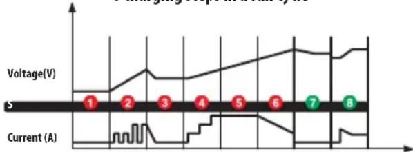
8 charging steps in a full cycle
line
| Voltage(V) | Current (A) | | ---------- | ----------- | | 1 | 2 | | 2 | 3 | | 3 | 4 | | 4 | 5 | | 5 | 6 | | 6 | 7 | | 7 | 8 |STEP 1: Diagnostics - Checks the battery voltage and connection.
STEP 2: Sulphur removal -If the battery voltage is too low, the programme generates the pulsating current automatically to remove sulphur deposits from the plates.
STEP 3: Analysis - Verifies if the battery voltage reaches the threshold value after sulphur removal. If the battery voltage is appropriate, the charging process starts.
STEP 4: Initial charging - Formatting charging with low-voltage direct current.
STEP 5: proper charging -Charging with direct current until the battery voltage reaches the rated value.
STEP 6: Charge absorption -Gradual reduction of the current value to accumulate the electrical charge as much as possible and achieve the maximum battery voltage.
STEP 7: Charging process analysis - Checking if the charging process is stable.
STEP 8: Stabilizing -Thanks to the smart processor, the charger monitors the battery status, adjusting the charging current to the battery voltage changes.
WARNING! If the battery is unable to start the vehicle following a complete charging cycle (except for any mechanical problems of the vehicle), the battery capacity is lower than the threshold value and the battery needs replacement.
Charging duration
Different internal capacity of the battery and the residual voltage may affect the charging duration. The data below are solely indicative.
| BATTERY CAPACITY (Ah) APPROXIMATE CHARGING DURATION (h) | |
| 20 10 | |
| 40 20 | |
| 60 30 | |
Error LED -Warning<!>
A flashing error LED indicates a problem making it impossible to use the battery. The battery may be charged only after the error is detected and removed. Sometimes a damaged battery cannot be repaired. It should be handed over to the specialist plant. Do not throw the battery in the municipal waste!
The error LED may indicate:
- The battery is not connected properly in the vehicle (no good conductance between the terminals and the clamps). Check and clean the battery terminal clamps, check the conductors.
- The battery voltage is too low.
- Incorrect conductor connection. Check if the positive (red) conductor of the charger is connected to the positive (+) battery terminal clamp and the negative one (black) to the negative (i) one.
Symbols on the charger rating plate

READ THE GUIDELINES AND PRODUCT SAFETY INFORMATION.

The product meets the requirements of EU directives

To be used indoors.

Symbol of a device with 2nd protection class

Fusing parameters of the fuse

Protection from dust and protection from water splashes from any direction

Do not mix the worn equipment with other waste.
Cleaning and maintenance
This device does not require maintenance.
Use a soft, moist (and not wet) cloth with a mild detergent for cleaning (only when disconnected from the mains). Do not use any acids or solvents.
Transport and storage
Transport and store in dry places out of reach of children. Protect from dust, moisture and mechanical damage.

This symbol means the prohibition to dispose of the worn device with other waste. The hazardous components of the electric and electronic equipment affect the natural environment and human health adversely. Households should contribute to the recovery and recycling of worn equipment. There is a worn equipment collection system created or already existing in Poland and Europe, with all points of sale of the said equipment being obliged to accept worn equipment. Moreover, there are points of collection for such equipment.
MANUFACTURER:
PROFIX SP. Z 0.0.
ul. Marywilska 34
03-228 Warsaw

line
| Voltage(V) | Current (A) | | ---------- | ----------- | | 1 | 0 | | 2 | 0 | | 3 | 0 | | 4 | 0 | | 5 | 0 | | 6 | 0 | | 7 | 0 | | 8 | 0 |Solis 1: Diagnostika – Pärbauda akumulatora spriegumu un pievienojumu.
Brand : PROLINE
Model : 46830
Category : Battery charger