
XFP-7D-41-PRO - NAS PROLINE - Free user manual and instructions
Find the device manual for free XFP-7D-41-PRO PROLINE in PDF.


| Product Type | XFP Transceiver |
| Compatibility | Rad® XFP-7D-41 compatible |
| Data Rate | 10.3125 Gbps (10GBase-DWDM) |
| Wavelength | 1544.53 nm (ITU-T Channel 41, 100GHz spacing) |
| Maximum Distance | 80 km over single-mode fiber |
| Connector | Duplex LC |
| Fiber Type | Single-mode |
| Form Factor | XFP MSA compliant |
| Hot-Pluggable | Yes |
| Digital Optical Monitoring (DOM) | Yes |
| Operating Temperature | 0 to 70°C |
| Storage Temperature | -40 to 85°C |
| Power Supply Voltage | 3.3V and 5V |
| Power Consumption | ≤ 3.5 W |
| Compliance | INF-8077i, TAA, RoHS |
| ESD Protection | Excellent |
| EMI Shielding | Metal with lower EMI |
| Warranty | Limited Lifetime |
Frequently Asked Questions - XFP-7D-41-PRO PROLINE
User questions about XFP-7D-41-PRO PROLINE
0 question about this device. Answer the ones you know or ask your own.
Ask a new question about this device
Download the instructions for your NAS in PDF format for free! Find your manual XFP-7D-41-PRO - PROLINE and take your electronic device back in hand. On this page are published all the documents necessary for the use of your device. XFP-7D-41-PRO by PROLINE.
USER MANUAL XFP-7D-41-PRO PROLINE
Rad® XFP-7D-41 Compatible TAA Compliant 10GBase-DWDM 100GHz XFP Transceiver (SMF, 1544.53nm, 80km, DOM, 0 to 70C, LC)
Features
• INF-8077i Compliance
• Temperature-stabilized EML transmitter and APD receiver
- Duplex LC Connector
• Commercial Temperature 0 to 70 Celsius
- Single-mode Fiber
- Hot Pluggable
• Excellent ESD Protection
• Metal with Lower EMI
• RoHS Compliant and Lead Free

Applications:
• 10x Gigabit Ethernet over DWDM
- 8x/10x Fibre Channel
- Access, Metro and Enterprise
Product Description
This Rad® XFP-7D-41 compatible XFP transceiver provides 10GBase-DWDM throughput up to 80km over single-mode fiber (SMF) using a wavelength of 1544.53nm via an LC connector. It is guaranteed to be 100% compatible with the equivalent Rad® transceiver. This easy to install, hot swappable transceiver has been programmed, uniquely serialized and data-traffic and application tested to ensure that it will initialize and perform identically. Digital optical monitoring (DOM) support is also present to allow access to real-time operating parameters. This transceiver is Trade Agreements Act (TAA) compliant. We stand behind the quality of our products and proudly offer a limited lifetime warranty.
Proline's transceivers are RoHS compliant and lead-free.
TAA refers to the Trade Agreements Act (19 U.S.C. & 2501-2581), which is intended to foster fair and open international trade. TAA requires that the U.S. Government may acquire only “U.S. – made or designated country end products.

Wavelength Guide (100GHz ITU-T Channel)
| Channel # | Frequency (THz) | Center Wavelength (nm) |
| 34 | 193.4 | 1550.12 |
| 35 | 193.5 | 1549.32 |
| 36 | 193.6 | 1548.51 |
| 37 | 193.7 | 1547.72 |
| 38 | 193.8 | 1546.92 |
| 39 | 193.9 | 1546.12 |
| 40 | 194.0 | 1545.32 |
| 41 | 194.1 | 1544.53 |
| 42 | 194.2 | 1543.73 |
| 43 | 194.3 | 1542.94 |
| 44 | 194.4 | 1542.14 |
| 45 | 194.5 | 1541.35 |
| 46 | 194.6 | 1540.56 |
| 47 | 194.7 | 1539.77 |
| 48 | 194.8 | 1538.98 |
| 49 | 194.9 | 1538.19 |
| 50 | 195.0 | 1537.40 |
| 51 | 195.1 | 1536.61 |
| 52 | 195.2 | 1535.82 |
| 53 | 195.3 | 1535.04 |
| 54 | 195.4 | 1534.25 |
| 55 | 195.5 | 1533.47 |
| 56 | 195.6 | 1532.68 |
| 57 | 195.7 | 1531.90 |
| 58 | 195.8 | 1531.12 |
| 59 | 195.9 | 1530.33 |
| 60 | 196.0 | 1529.55 |
| 61 | 196.1 | 1528.77 |
Absolute Maximum Ratings
| Parameter | Symbol | Min. | Max. | Unit |
| Maximum Supply Voltage | Vcc3 | -0.5 | 3.6 | V |
| Vcc5 | -0.5 | 6 | V | |
| Storage Temperature | TS | -40 | 85 | °C |
| Operating Temperature | TO | 0 | 70 | °C |
| Operating Humidity | RH | 5 | 95 | % |
| Receiver power | R_MAX | -8 | dBm | |
| Maximum bitrate | B_max | 11.3 | Gbps |
Electrical Characteristics
| Parameter | Symbol | Min. | Typ. | Max. | Unit | Notes |
| Power Supply Voltage | Vcc3 | 3.135 | 3.30 | 3.465 | V | |
| Vcc5 | 4.75 | 5.0 | 5.25 | V | ||
| Power Supply Current | Icc | 1061 | mA | |||
| Power Consumption | P_Diss | 3.5 | W | |||
| Transmitter | ||||||
| Differential data input swing | Vin,pp | 120 | 850 | mV | ||
| Input differential impedance | Zin | 80 | 100 | 120 | Ω | |
| Receiver | ||||||
| Differential data output swing | Vout, pp | 300 | 850 | mV | ||
| Output differential impedance | Zin | 80 | 100 | 120 | Ω | |
Optical Characteristics
| Parameter | Symbol | Min. | Typ. | Max. | Unit | Notes |
| Transmitter | ||||||
| Optical Power (average) | P_AVE | 0 | 5 | dBm | 1 | |
| Transmitter and Dispersion Penalty | TDP | 3 | dB | |||
| Optical Extinction Ratio | ER | 9 | dB | |||
| Optical Wavelength | Tλ | x-0.1 | X | X+0.1 | nm | |
| Insertion loss | IL | 0.35 | ||||
| Receiver | ||||||
| Receiver Sensitivity (average) | R_AVE | -23 | dBm | 2 | ||
| Receiver overload | P_max | -8 | dBm | 3 | ||
| Receiver wavelength | Rλ | 1260 | 1620 | nm | ||
Notes:
- Coupled into a Single mode fibre
- Average power, back-to-back, @10.31Gbps, BER 1E-12, PRBS 231-1.
- Exceeding the Receiver overload can physically damage the module. Please use appropriate attenuation.
Pin Descriptions
| Pin | Symbol | Name/Descriptions | Ref. |
| 1 | GND | Module Ground | |
| 2 | Vee5 | (not required) | |
| 3 | MOD_DESEL | Module De-select; When Held low allows the module to respond to 2-wire serial interface. LVTTL-I | |
| 4 | /INTERRUPT | Interrupt; Indicates presence of an important condition which can be read via the 2-wire serial interface. LVTTL-O | 2 |
| 5 | TX_DIS | Transmitter Disable. Logic1 indicates laser output disabled, LVTTL-I | |
| 6 | VCC5 | +5V Power Supply (Not required) | |
| 7 | GND | Module Ground | 1 |
| 8 | VCC3 | +3.3V Power Supply | |
| 9 | VCC3 | +3.3V Power Supply | |
| 10 | SCL | 2-Wire Serial Interface Clock. LVTTL-I | 2 |
| 11 | SDA | 2-Wire Serial Interface Data Line. LVTTL-I/O | 2 |
| 12 | MOD_Abs | Indicates Module is not present. Grounded in the Module. LVTTL-O | 2 |
| 13 | MOD_NR | Module Not Ready; Indicating Module Operational Fault. Open-collector. LVTTL-O | 2 |
| 14 | RX_LOS | Loss of Signal indication. Logic 1 indicates loss of Signal. Open-collector. LVTTL-O | 2 |
| 15 | GND | Module Ground | 1 |
| 16 | GND | Module Ground | 1 |
| 17 | RD- | Receiver Inverted Data Output. CML-O | |
| 18 | RD+ | Receiver Non-Inverted Data Output. CML-O | |
| 19 | GND | Module Ground | 1 |
| 20 | VCC2 | +1.8V Power Supply (Not required). | 3 |
| 21 | P_DOWN/RST | Power down; When high, requires the module to limit power consumption to 1.5W or below. 2-Wire serial interface must be functional in the low power mode. LVTTL-I | |
| Reset; The falling edge initiates a complete reset of the module including the 2-wire serial interface, equivalent to a power cycle. LVTTL-I | |||
| 22 | VCC2 | +1.8V Power Supply (Not required) | 3 |
| 23 | GND | Module Ground | 1 |
| 24 | REFCLK+ | Reference Clock (Not required) | |
| 25 | REFCLK- | Reference Clock (Not required) | |
| 26 | GND | Module Ground | 1 |
| 27 | GND | Module Ground | 1 |
| 28 | TD- | Transmitter Inverted Data Input. CML-I | |
| 29 | TD+ | Transmitter Non-Inverted Data Input. CML-I | |
| 30 | GND | Module Ground | 1 |
Notes:
- Module ground pins GND are isolated from the module case and chassis ground within the module.
- Open collector; should be pulled up with 4.7K-10Kohms to a voltage between 3.15V and 3.6V on the host board.
- The pins are open within module.

Pin-out of connector Block on Host board
Recommended Circuit Schematic

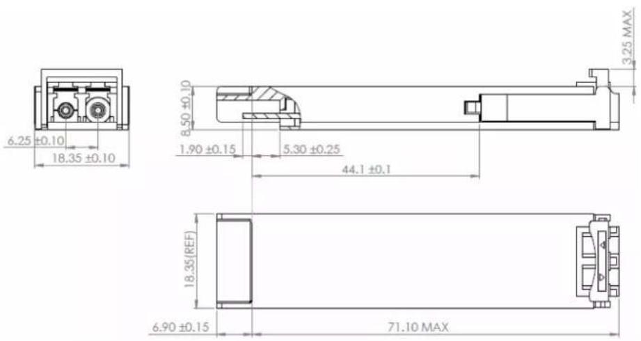
Mechanical Specifications
Small Form Factor Pluggable (XFP) transceivers are compatible with the dimensions defined by the XFP Multi-Sourcing Agreement (MSA).
EEPROM Information
Management Interface
XFP 2-wire serial interface is specified in the Chapter 4 of the XFP MSA specification. The XFP 2-wire serial interface is used for serial ID, digital diagnostics, and certain control functions. The 2-wire serial interface is mandatory for all XFP modules. The 2-wire serial interface address of the XFP module is 1010000X(A0h). In order to access to multiple modules on the same 2-wire serial bus, the XFP has a MOD_DESEL(module deselect pin). This pin (which is pull high or deselected in the module) must be held low by the host to select of interest and allow communication over 2-wire serial interface. The module must not respond to or accept 2-wire serial bus instructions unless it is selected.
XFP Management Interface
XFP Management interface is specified in the Chapter 5 of the XFP MSA specification. The Figure 1 shows the structure of the memory map. The normal 256 Byte address space is divided into lower and upper blocks of 128 Bytes. The lower block of 128 Byte is always directly available and is used for the diagnostics and control functions that must be accessed repeatedly. Multiple blocks of memories are available in the upper 128 Bytes of the address space. These are individually addressed through a table select Byte which the user enters into a location in the lower address space. The upper address space tables are used for less frequently accessed functions and control space for future standards definition.
EEPROM memory map specific data field description is as below:

flowchart
graph TD
    A["2-Wire Serial Address 1010000X (A0H)"] --> B["Digital Diagnostic Functions"]
    B --> C["4 Byte Password Change"]
    B --> D["4 Byte Password Entry"]
    B --> E["Page Select Byte Entry"]
    B --> F["Reserved for Future Diagnostic Functions"]
    B --> G["XFP MSA Serial ID Data"]
    B --> H["User EEPROM Data"]
    B --> I["Vendor Specific Functions"]
    B --> J["Reserved"]
    F --> K["Table 00h"]
    G --> L["Table 01h"]
    H --> M["Table 02h"]
    I --> N["Table 03h-7Fh"]
    J --> O["Table 80h-FFh"]
About Us:
Proline Options is one of North America's leading providers of transceivers and high speed cabling. With a reputation for quality, tested products that cover the connectivity spectrum, Proline Options has a solution for you regardless of the specification.
At Proline Options, every product is tested in its intended application - never batch or spec tested only. We run bandwidth, distance and IOS network tests. We have documented an impressive 0.03% failure rate over the last 10 years. To continue this rate of success we invest millions annually in our own on-site testing lab.

9001:2015

COMPLIANT





Intertek
Tel: 855.933.3223
Email: sales@prolineoptions.com
Email: techsupport@prolineoptions.com
Web: https://www.prolineoptions.com
Brand : PROLINE
Model : XFP-7D-41-PRO
Category : NAS