
C272 - Audio Amplifier NAD - Free user manual and instructions
Find the device manual for free C272 NAD in PDF.



| Product Type | Stereo Power Amplifier |
| Output Power | 2 x 150 W (stereo, 8 ohms) / 1 x 400 W (bridged mono, 8 ohms) |
| Speaker Impedance | 4 to 8 ohms (stereo), 8 ohms minimum (bridged) |
| Audio Inputs | 2 RCA pairs (Fixed Input and Variable Input) |
| Speaker Outputs | 2 pairs of binding posts (A and B) compatible with bi-wiring |
| Bridged Mode | Yes, selectable via Bridge Mode switch |
| Soft Clipping | Yes, exclusive NAD circuit limiting distortion at high volume |
| 12V Trigger | 12V trigger input (3.5mm mini-jack) for remote power-on |
| Signal Sensing (Sleep/Wake) | Yes, with Sense LED; automatically enters standby after 5 minutes without signal |
| Vacation Switch | Vacation switch to cut power during extended standby |
| Protection | Protection circuit against overheating, short circuit, and low impedance |
| Power Supply | Mains 230 V AC (50/60 Hz) |
| Dimensions (W x H x D) | 435 x 145 x 340 mm |
| Weight | 12 kg |
| Input Color Coding | Red for right channel, white for left channel |
Frequently Asked Questions - C272 NAD
User questions about C272 NAD
0 question about this device. Answer the ones you know or ask your own.
Ask a new question about this device
Download the instructions for your Audio Amplifier in PDF format for free! Find your manual C272 - NAD and take your electronic device back in hand. On this page are published all the documents necessary for the use of your device. C272 by NAD.
USER MANUAL C272 NAD
IMPORTANT SAFETY INSTRUCTIONS
CAUTION
RISK OF ELECTRIC SHOCK DO NOT OPEN
ATTENTION:
RISQUE DE CHOC ELECTRIQUE NE PAS OUVRIR

CAUTION: TO REDUCE THE RISK OF ELECTRIC SHOCK, DO NOT REMOVE COVER (OR BACK). NO USER SERVICEABLE PARTS INSIDE. REFER SERVICING TO QUALIFIED SERVICE PERSONNEL.
Warning: To reduce the risk of fire or electric shock, do not expose this unit to rain or moisture.
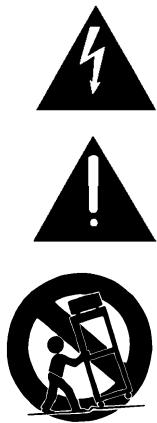
The lightning flash with an arrowhead symbol within an equilateral triangle, is intended to alert the user to the presence of uninsulated "dangerous voltage" within the product's enclosure that may be of sufficient magnitude to constitute a risk of electric shock to persons.
The exclamation point within an equilateral triangle is intended to alert the user to the presence of important operating and maintenance (servicing) instructions in the literature accompanying the product.
Do not place this unit on an unstable cart, stand or tripod, bracket or table. The unit may fall, causing serious injury to a child or adult and serious damage to the unit. Use only with a cart, stand, tripod, bracket or table recommended by the manufacturer or sold with the unit. Any mounting of the device on a wall or ceiling should follow the manufacturer's instructions and should use a mounting accessory recommended by the manufacturer.
An appliance and cart combination should be moved with care. Quick stops, excessive force and uneven surfaces may cause the appliance and cart combination to overturn.
Read and follow all the safety and operating instructions before connecting or using this unit. Retain this notice and the owner's manual for future reference.
All warnings on the unit and in its operating instructions should be adhered to.
Do not use this unit near water; for example, near a bath tub, washbowl, kitchen sink, laundry tub, in a wet basement or near a swimming pool.
The unit should be installed so that its location or position does not interfere with its proper ventilation. For example, it should not be situated on a bed, sofa, rug or similar surface that may block the ventilation openings; or placed in a built-in installation, such as a bookcase or cabinet, that may impede the flow of air through its ventilation openings.
The unit should be situated from heat sources such as radiators, heat registers, stoves or other devices (including amplifiers) that produce heat.
The unit should be connected to a power supply outlet only of the voltage and frequency marked on its rear panel.
The power supply cord should be routed so that it is not likely to be walked on or pinched, especially near the plug, convenience receptacles, or where the cord exits from the unit.
Unplug the unit from the wall outlet before cleaning. Never use benzine, thinner or other solvents for cleaning. Use only a soft damp cloth.
The power supply cord of the unit should be unplugged from the wall outlet when it is to be unused for a long period of time.
Care should be taken so that objects do not fall, and liquids are not spilled into the enclosure through any openings.
This unit should be serviced by qualified service personnel when:
A. The power cord or the plug has been damaged; or
B. Objects have fallen, or liquid has been spilled into the unit; or
C. The unit has been exposed to rain or liquids of any kind; or
D. The unit does not appear to operate normally or exhibits a marked change in performance; or
E. The device has been dropped or the enclosure damaged.
DO NOT ATTEMPT SERVICING OF THIS UNIT YOURSELF. REFER SERVICING TO QUALIFIED SERVICE PERSONNEL
Upon completion of any servicing or repairs, request the service shop's assurance that only Factory Authorized Replacement Parts with the same characteristics as the original parts have been used, and that the routine safety checks have been performed to guarantee that the equipment is in safe operating condition. REPLACEMENT WITH UNAUTHORIZED PARTS MAY RESULT IN FIRE, ELECTRIC SHOCK OR OTHER HAZARDS.
ATTENTION
POUR ÉVITER LES CHOC ELECTRIQUES, INTRODUIRE LA LAME LA PLUS LARGE DE LA FICHE DANS LA BORNE CORRESPONDANTE DE LA PRISE ET POUSSER JUSQU'AU FOND.
CAUTION
TO PREVENT ELECTRIC SHOCK, MATCH WIDE BLADE OF PLUG TO WIDE SLOT FULLY INSERT.
If an indoor antenna is used (either built into the set or installed separately), never allow any part of the antenna to touch the metal parts of other electrical appliances such as a lamp, TV set etc.
CAUTION POWER LINES
Any outdoor antenna must be located away from all power lines.
OUTDOOR ANTENNA GROUNDING
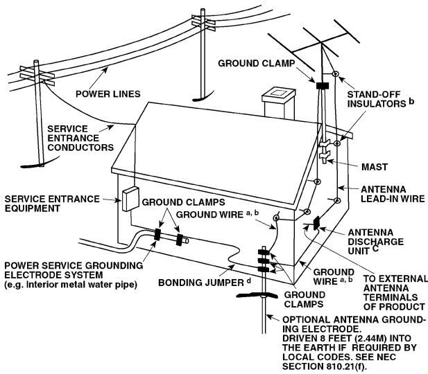
If an outside antenna is connected to your tuner or tuner-preamplifier, be sure the antenna system is grounded so as to provide some protection against voltage surges and built-up static charges. Article 810 of the National Electrical Code, ANSI/NFPA No. 70-1984, provides information with respect to proper grounding of the mast and supporting structure, grounding of the lead-in wire to an antenna discharge unit, size of grounding conductors, location of antenna discharge unit, connection to grounding electrodes and requirements for the grounding electrode.
a. Use No. 10 AWG (5.3mm2) copper, No. 8 AWG (8.4mm2) aluminium, No. 17 AWG (1.0mm2) copper-clad steel or bronze wire, or larger, as a ground wire.
b. Secure antenna lead-in and ground wires to house with stand-off insulators spaced from 4-6 feet (1.22 - 1.83 m) apart.
c. Mount antenna discharge unit as close as possible to where lead-in enters house.
d. Use jumper wire not smaller than No.6 AWG (13.3mm2) copper, or the equivalent, when a separate antenna-grounding electrode is used. see NEC Section 810-21 (j).
EXAMPLE OF ANTENNA GROUNDING AS PER NATIONAL ELECTRICAL CODE INSTRUCTIONS CONTAINED IN ARTICLE 810 - RADIO AND TELEVISION EQUIPMENT.
NOTE TO CATV SYSTEM INSTALLER: This reminder is provided to call the CATV system installer's attention to Article 820-40 of the National Electrical Code that provides guidelines for proper grounding and, in particular, specifies that the ground cable ground shall be connected to the grounding system of the building, as close to the point of cable entry as practical.
REAR PANEL CONNECTIONS (FIGURE 1)
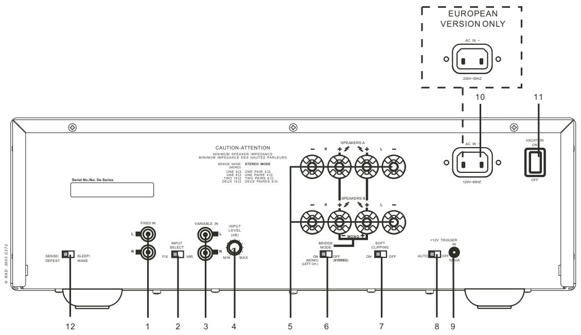
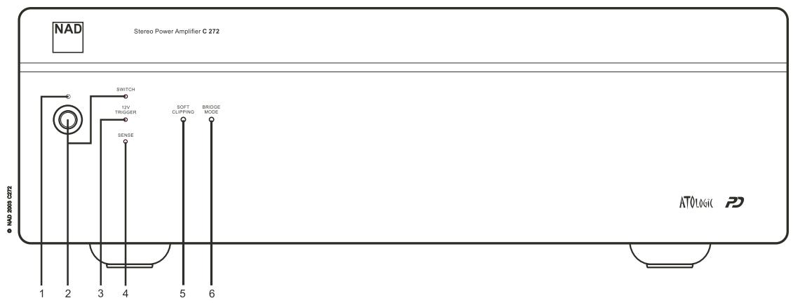
FRONT PANEL CONTROLS (FIGURE 2)
NAD C 272 Stereo Power Amplifier
QUICK START
- Connect the speakers to the Speaker A terminals and pre-amplifier to the "FIXED IN" inputs.
- Plug in the AC power cord.
- Press the POWER button to turn the NAD C 272 on.
- Press the required input selector.
NOTES ON INSTALLATION
Your NAD C 272 should be placed on a firm, level surface. Avoid placing the unit in direct sunlight or near sources of heat and damp. Allow adequate ventilation. Do not place the unit on a soft surface like a carpet. Do not place it in an enclosed position, such a bookcase or cabinet, that may impede the airflow through the ventilation slots. Make sure the unit is switched off before making any connections.
The RCA sockets on your NAD C 272 are colour coded for convenience. Red and white are Right and Left audio respectively. Use high quality leads and sockets for optimum performance and reliability. Ensure that leads and sockets are not damaged in any way and all sockets are firmly pushed home.
For best performance, use quality speaker leads of 16 gauge (1.5mm) thickness or more. If the unit is not going to be used for some time, disconnect the plug from the AC socket.
Should water get into your NAD C 272, shut off the power to the unit and remove the plug from the AC socket. Have the unit inspected by a qualified service technician before attempting to use it again. DO NOT REMOVE THE COVER, THERE ARE NO USER-SERVICEABLE PARTS INSIDE.
Use a dry soft cloth to clean the unit. If necessary, lightly dampen the cloth with soapy water. Do not use solutions containing benzol or other volatile agents.
REAR PANEL CONNECTIONS (FIGURE 1)
1. FIXED IN
The Fixed Inputs take the input signal straight to the power amplifier's circuitry. This set of inputs is normally used in a system with only one power amplifier or multiple but identical power amplifiers. Refer also to section "Variable In" in this chapter for more information.
Connect the output from a pre-amplifier or processor, such as a surround-sound decoder, to this set of inputs. Use a twin RCA-to-RCA lead to connect to the left and right 'Audio Output' of the pre-amp or processor to the Fixed-In sockets.
NOTES: Always turn the C 272 and other components in the system off before connecting or It is disconnecting anything to the "Fixed In" or Variable In" sockets.
When using the Fixed In sockets, make sure the "Input Select" switch (No.2) is to the "Fix" position.
2. INPUT SELECT
The Input Select switch determines which input on the C 272 is active. Set to "FIX" for use with "Fixed In" and to "VAR" for use with "Variable In". Refer also to section "Variable In" in this chapter for more information.
3. VARIABLE IN
Using the Variable inputs, it is possible to adjust the volume level for both channels simultaneously, using the Input Level Control (No. 4). This can be useful for:
- Level matching
In a surround sound or system with more than one set of speakers, differences in levels can occur due to variances in efficiency between these speakers. In case your preamplifier or processor also has individual trims for each channel, set these to neutral or mid position (usually marked as 0dB). Adjust the Level Control so that the speakers driven by the C 272 have the correct volume level compared to the other speakers, judging from your listening position.
• Extended volume control range
Many systems have so much voltage gain that the speakers (or your ears) are overdriven at any volume control setting higher than 11 or 12 o'clock. As a result you are confined to using only the lower half of the volume control's range, where adjustments are imprecise and where channel balance errors tend to be greater. If the input level is reduced, you can turn up your processor's or preamplifier's volume control, making more effective use of its range. (Suggestion: adjust the input level controls so that your preferred maximum sound levels usually occur at about 2 or 3 o'clock on the volume control.) As an added benefit, this procedure suppresses any noise produced by the preamp's high level circuitry (e.g. any residual hum or hiss that does not go away when the Volume is turned down).
- Bi-Amping
Some loudspeakers have separate connection terminals for the LF (Low Frequency) and HF (High Frequency) sections of the speaker. This facility allows to "Bi-Amp" such speakers, where a separate power amplifier is used for the LF and HF section, which may improve overall sound quality. When Bi-Amping with different models of power amplifiers, it is likely to occur that one power amplifier has more "gain" than the other, resulting in a mis-match in level for the woofer and tweeter of the speaker. Adjust the level control so that woofer and tweeter are in perfect balance with each other (identical gain of power amplifiers).
Connect the output from a pre-amplifier or processor, such as a surround-sound decoder, to this set of inputs. Use a twin RCA-to-RCA lead to connect to the left and right 'Audio Output' of the pre-amp or processor to the Fixed-In sockets.
NOTES: Always turn the C 272 and other components in the system off before connecting or disconnecting anything to the "Fixed In" or Variable In" sockets.
When using the "Variable In" sockets, make sure the "input Select" switch (No.2) is to the "VAR" position.
4. INPUT LEVEL CONTROL
The Input Level control works in combination with “Variable In” (No. 3) only. With the control the volume to the power amplifier can be adjusted from zero (counter clock-wise) to maximum (turned up all the way clock-wise). Refer also to section “Variable In” in this chapter for more information.
NOTE: Always turn the C 272 and other components in the system off before connecting or disconnecting anything to the "Fixed In" or Variable In" sockets.
5. SPEAKERS A & SPEAKERS B
The NAD C 272 is equipped with two sets of speaker connectors wired in parallel to facilitate connection of multiple pairs of speakers or "Bi-Wiring". Use the Speakers A connectors for the 'main' speakers and use the Speakers B connectors for a second pair, for example, extension speakers located in another room.
Under normal operation, connect the right speaker to the terminals market 'R +' and 'R-' ensuring that the 'R+' is connected to the '+' terminal on your loudspeaker and the 'R-' is connected to the loudspeaker's '-' terminal. Connect the terminals marked 'L+' and 'L-' to the left speaker in the same way.
In Bridge Mode, connect the single speaker to the terminals marked 'R +' and 'L+' ensuring that the 'L+' is connected to the '+' terminal on your loudspeaker and the R+ is connected to the loudspeaker's '-' terminal. Refer also to section "Bridge Mode" in this chapter (No. 6).
Always use heavy duty (16 gauge; 1.5mm, or thicker) stranded wire to connect loudspeakers to your NAD C 272. The high-current binding post terminals can be used as a screw terminal for cables terminating in spade or pin sockets or for cables with bare wire ends.
BARE WIRES AND PIN CONNECTORS
Bare wires and pin sockets should be inserted into the hole in the shaft of the terminal. Unscrew the speaker terminal's plastic bushing until the hole in the screw shaft is revealed. Insert the pin or bare cable end into the hole and secure the cable by tightening down the terminal's bushing. Ensure bare wire from the speaker cables does not touch the back panel or another socket. Ensure that there is only 1/2" (1cm) of bare cable or pin and no loose strands of speakers wire.
NOTE: Make sure the speaker impedance is 4 ohms or more when connecting only one pair of speakers; make sure the speaker impedance for all speakers is over 8 ohms when connecting two sets of speakers. In Bridge Mode, the impedance of the loudspeaker should also be 8 ohms or higher.
Always turn the C 272 and other components in the system off before connecting or disconnecting speakers.
6. BRIDGE MODE
The stereo NAD C 272 power amplifier can be configured to be mono (Bridge Mode), more than doubling its output power: 2 x 150 vs. 1 x 400 Watt. This way, the NAD C 272 can be used as part of a high power stereo or home-theatre system, by connecting adding additional power amplifiers.
Set the BRIDGE MODE switch to the "Bridge" position and connect the speaker to the terminals marked 'L+' and 'R+' ensuring that the 'L+' is connected to the '+' terminal on your loudspeaker and the 'R+' is connected to the loudspeaker's '-' terminal. Connect the source to the Left FIXED, or VARIABLE input.
In Bridged Mode the NAD C 272 will produce approximately 400W into an 8 ohm loudspeaker. In this mode, the amplifier sections will react as though the speaker impedance has been halved. Low impedance speakers (under 8 ohms) are not recommended when using Bridge Mode, as these may cause the amplifier's thermal cut-out to operate if played at high levels.
The Bridge Mode indicator on the front panel (Fig. 2; No. 6) will illuminate when the amplifier is in Bridge mode.
NOTES: Do not connect anything to the Right "Fixed In" or Right "Variable In" sockets when Bridge Mode is selected.
Always turn the C 272 and other components in the system off before connecting or disconnecting anything to the "Fixed In" or Variable In" sockets.
7. SOFT CLIPPING™
When an amplifier is driven beyond its specified power output, a hard, distorted sound can be heard on very loud sounds. This is caused by the amplifier cutting off or 'hard clipping' the peaks of sound that it was not designed to reproduce. The NAD Soft Clipping™ circuit gently limits the output of the system to minimise audible distortion if the amplifier is overdriven.
If your listening involves moderate power levels you may leave the Soft Clipping™ switch to Off. If you are likely to play at high levels, that could stretch the amplifier's power capability, then switch Soft Clipping™ On.
The Soft Clipping™ indicator on the front panel will illuminate when the amplifier is in Soft Clip mode.
8. 12V TRIGGER AUTO ON-OFF
The C 272's 12V trigger input allows it to be switched to On and Stand-by remotely by an external component.
Set the 12V Trigger switch set to the "ON" position to activate the 12V Trigger input. When the switch is set to the Off position, the 12V trigger input is not active. Refer to section "12V Trigger In" below for more information.
9. 12V TRIGGER IN
This input allows the C 272 to be switched remotely to stand-by and on or by ancillary equipment such as a preamp, AV processor, etc. which are also equipped with a 12V trigger output.
For switching Stand-by/Power On of the C 272 by an external component, connect the12V-trigger input of the C 272 to the remote component's DC output jack. The plug required is a standard 3.5mm Mini-Jack plug ("mono"): The tip is the live or + connection, the shaft of the input jack is the 12V-trigger - or ground connection.
NOTES: The C 272's 12V Trigger will work within a range of 6 to 15 V DC level and typically draws less than 10mA of current. Check the specifications of the Trigger output terminal on the remote component to ensure it is compatible with the C 272's 12V-trigger input. NAD components equipped with 12V output triggers are fully compatible with the C 272's 12V input trigger.
Before making any connections to any 12V trigger input or output, make sure all components are disconnected from the AC mains.
Failure to observe the above may result in damage to the C 272 or any ancillary components attached to it. If in doubt over the connections, installation and operation of the 12V trigger output consult your NAD dealer.
10. AC LINE CORD
Plug the AC power cord into a live AC wall socket. Make sure all connections have been made before connecting to mains.
11. VACATION ON/OFF
The VACATION switch is the master on/off control for the amplifier. When the switch is in the ON state the amplifier is in standby as shown
by the amber LED above the power switch on the front panel. If the amplifier will not be used for an extended period of time, switch the VACATION switch to the OFF position.
12. SLEEP/WAKE-SENSE/DEFEAT
The SLEEP/WAKE, SENSE/DEFEAT switch logic controls the standby/on-state of the amplifier via the presences or absence of audio signal at the amplifier channel inputs. The SLEEP/WAKE, SENSE/DEFEAT switch must be in the SLEEP/WAKE position in order to use this logic. When the SLEEP/WAKE, SENSE/DEFEAT switch is in the SENSE/DEFEAT position, this logic control is deactivated.
When the switch is in the SLEEP/WAKE position, the C 272 amplifier will instantaneously turn on from a standby state, sensing any input signal from any channel as seen by a lit green SENSE LED on the front panel of the amplifier (approximately above 20mV RMS input). If all of the audio signals are absent for approximately 5 minutes, the amplifier will switch automatically to standby condition, with the green SENSE LED off, and the amber LED over the front panel switch lit.
FRONT PANEL CONTROLS (FIGURE 2)
1. STAND-BY/PROTECTION INDICATOR
Upon switching Power on, the indicator will light up red and after a short pause turn to green to indicate the amplifier is ready for use.
In cases of serious abuse of the amplifier, such as overheating, excessively low loudspeaker impedance, short circuit, etc. the amplifier will engage its Protection circuitry. The indicator will light up red and the sound will be muted. In such a case, turn the amplifier off, wait for it to cool down and/or check the speaker connections, making sure the overall loudspeaker impedance doesn't go below 4 ohms or 8 ohms in Bridge Mode. Once the cause for the protection circuitry to engage has been removed, switch the amplifier On again.
The diagram below shows the operation of the Stand-by/protection indicator:
| Green | Amber | Red | |
| Normal Operation | ● | ||
| Stand-by | ● | ||
| Protection | ● |
2. POWER ON/OFF
Press this button to switch the amplifier on or off. The Power On/Standby (No. 1) indicator located just above the power button and Protection indicator will light up. After a few seconds, the Protection LED will turn off, indicating that the amplifier is ready for use.
3. TRIGGER INDICATOR
The 12V-TRIGGER LED illuminates green when the amplifier switches from standby to power on state via the 12V input (refer to "Rear-Panel Connections": 12V-TRIGGER INPUT section). Once you turn on the amplifier via the 12V-IN TRIGGER, only the absence of the 12V can return the amplifier to standby state.
4. SENSE INDICATOR
The SENSE LED illuminates green when the amplifier senses a signal greater than 20mV RMS on any of the amplifier inputs refer to "Rear-Panel Controls and Connections": SLEEP/WAKE, SENSE/DEFEAT section). Once you turn on the amplifier via the SLEEP/WAKE sense logic, only the absence of a signal to all the amplifier's inputs can return the amplifier to standby state.
5. SOFT CLIPPING™ INDICATOR
The green SOFT CLIPPING™ indicator shows that the Soft Clipping™ mode is engaged. Refer also to chapter "Rear Panel Connections", section 7; "Soft Clipping™" for more information.
6. BRIDGE MODE INDICATOR
The BRIDE MODE indicator lights up (amber) when the C 272 is switched to Bridge Mode. Refer also to chapter "Rear Panel Connections", section 6, "Bridge Mode" for more information.
ATO LOGIC
The C 272 amplifier may be turned on in any one of three discrete ways for complete system flexibility: From the front-panel switch, the 12V-TRIGGER circuit, or by a "SLEEP/WAKE" signal-sensing circuit. The ON/OFF power control is managed by the Automated Turn-On logic or ATO Logic circuit that requires the amplifier to be switched back to standby in the same manner by which it was activated. In other words, if the amplifier is switched on via a 12V-control signal, it cannot be switched to standby via the front-panel switch, it must wait for removal of the 12V-control signal. In practice, you probably would use only one of the methods once the NAD C 272 amplifier is installed.
ATO LOGIC CHART
| SWITCH | Amber LED over front power switch | Green SWITCH LED | Green 12V-TRIGGER LED | Green SENSE LED |
| VACATION switch set to OFF | OFF | OFF | OFF | OFF |
| VACATION switch set to ON | Amber | OFF | OFF | OFF |
| Press front power switch with VACATION switch set to ON | Green | ON | OFF | OFF |
| Press front power switch with VACATION switch set to ON | Amber | OFF | OFF | OFF |
| 12V TRIGGER | Amber LED over front power switch | Green SWITCH LED | Green 12V-TRIGGER LED | Green SENSE LED |
| VACATION switch set to OFF | OFF | OFF | OFF | OFF |
| VACATION switch set to ON | Amber | OFF | OFF | OFF |
| 12 V INPUT TRIGGER = 0V with VACATION switch set to ON | Amber | OFF | OFF | OFF |
| 12V INPUT TRIGGER = 12V with VACATION switch set to ON | Green | OFF | ON | OFF |
| SLEEP/WAKE | Amber LED over front power switch | Green SWITCH LED | Green 12V-TRIGGER LED | Green SENSE LED |
| VACATION switch set to OFF | OFF | OFF | OFF | OFF |
| VACATION switch set to ON | Amber | OFF | OFF | OFF |
| SLEEP/WAKE SENSE DEFEAT switch set to SENSE DEFEAT with VACATION switch set to ON | Amber | OFF | OFF | OFF |
| SLEEP/WAKE SENSE DEFEAT switch set to SLEEP/WAKE and any source input greater than 20mV with VACATION switch set to ON | Green | OFF | OFF | ON |

| TROUBLESHOOTING | ||
| Problem | Cause | Solution |
| NO SOUND | Power AC lead unplugged or power not switched onInput Select switch not set to active inputInput Level Control turned down | Check if AC lead is plugged in and power switched onSet switch to the active inputTurn control up to the correct level |
| NO SOUND ONE CHANNEL | Balance control not centredSpeaker not properly connected or damagedInput lead disconnected or damaged | Centre Balance controlCheck connections and speakersCheck leads and connections |
| WEAK BASS / DIFFUSE OR NO STEREO IMAGE | Speakers wired out of phaseBridge Mode selected when speakers are connected normally | Check connections to all speakers in the systemDisengage Bridge Mode |
| POWER/PROTECTION LED STAYS RED UPON TURNING POWER ON | Loudspeakers cabling has a short-circuit | Turn amplifier off and check loudspeaker cable connections for both speakers at amplifier's back panel and loudspeakers. Turn amplifier on |
| POWER/PROTECTION INDICATOR TURNS RED DURING OPERATION | Amplifier has over-heatedOverall impedance of loudspeakers too low | Turn amplifier off. Make sure ventilation slots on top and bottom of amplifier aren't blocked. After amplifier has cooled down, turn back onEnsure the overall loudspeaker impedance isn't below 4 ohmsCheck loudspeaker cables for short circuits |

1. ENTREE FIXE [FIXED IN]
12. SLEEP/WAKE, SENSE/DEFEAT
2. "POWER ON/OFF" (ACCESO/SPENTO)
6. BRIDGE MODE INDICATOR
ANSLUTNINGAR PÅ APPARATENS BAKSIDA (FIGURE 1)
1. FIXED IN
www.NADelectronics.com
©2003 NAD ELECTRONICS
- IMPORTANT SAFETY INSTRUCTIONS
- DO NOT ATTEMPT SERVICING OF THIS UNIT YOURSELF. REFER SERVICING TO QUALIFIED SERVICE PERSONNEL
- ATTENTION
- CAUTION
- CAUTION POWER LINES
- OUTDOOR ANTENNA GROUNDING
- NAD C 272 Stereo Power Amplifier
- QUICK START
- NOTES ON INSTALLATION
- REAR PANEL CONNECTIONS (FIGURE 1)
- FIXED IN
- INPUT SELECT
- VARIABLE IN
- - Level matching
- • Extended volume control range
- - Bi-Amping
- INPUT LEVEL CONTROL
- SPEAKERS A & SPEAKERS B
- BARE WIRES AND PIN CONNECTORS
- BRIDGE MODE
- SOFT CLIPPING™
- 12V TRIGGER AUTO ON-OFF
- 12V TRIGGER IN
- AC LINE CORD
- VACATION ON/OFF
- SLEEP/WAKE-SENSE/DEFEAT
- FRONT PANEL CONTROLS (FIGURE 2)
- STAND-BY/PROTECTION INDICATOR
- POWER ON/OFF
- TRIGGER INDICATOR
- SENSE INDICATOR
- SOFT CLIPPING™ INDICATOR
- BRIDGE MODE INDICATOR
- ATO LOGIC
- ENTREE FIXE [FIXED IN]
- SLEEP/WAKE, SENSE/DEFEAT
- "POWER ON/OFF" (ACCESO/SPENTO)
- ANSLUTNINGAR PÅ APPARATENS BAKSIDA (FIGURE 1)
- ©2003 NAD ELECTRONICS
Brand : NAD
Model : C272
Category : Audio Amplifier