USER MANUAL JR3060T MAKITA
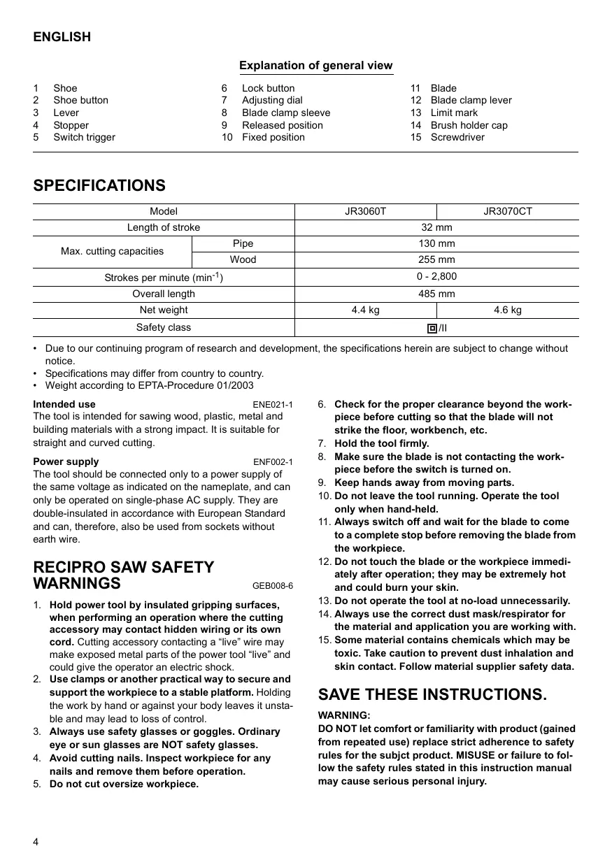
Explanation of general view
1 Shoe
6 Lock button
11 Blade
2 Shoe button
7 Adjusting dial
12 Blade clamp lever
3 Lever
8 Blade clamp sleeve
13 Limit mark
4 Stopper
9 Released position
14 Brush holder cap
5 Switch trigger
10 Fixed position
15 Screwdriver
SPECIFICATIONS
| Model | JR3060T | JR3070CT |
| Length of stroke | 32 mm |
| Max. cutting capacities | Pipe | 130 mm |
| Wood | 255 mm |
| Strokes per minute (min-1) | 0 - 2,800 |
| Overall length | 485 mm |
| Net weight | 4.4 kg | 4.6 kg |
| Safety class | 回/II |
- Due to our continuing program of research and development, the specifications herein are subject to change without notice.
- Specifications may differ from country to country.
Weight according to EPTA-Procedure 01/2003
Intended use
ENE021-1
The tool is intended for sawing wood, plastic, metal and building materials with a strong impact. It is suitable for straight and curved cutting.
Power supply
ENF002-1
The tool should be connected only to a power supply of the same voltage as indicated on the nameplate, and can only be operated on single-phase AC supply. They are double-insulated in accordance with European Standard and can, therefore, also be used from sockets without earth wire.
RECIPRO SAW SAFETY WARNINGS
GEB008-6
- Hold power tool by insulated gripping surfaces, when performing an operation where the cutting accessory may contact hidden wiring or its own cord. Cutting accessory contacting a "live" wire may make exposed metal parts of the power tool "live" and could give the operator an electric shock.
- Use clamps or another practical way to secure and support the workpiece to a stable platform. Holding the work by hand or against your body leaves it unstable and may lead to loss of control.
- Always use safety glasses or goggles. Ordinary eye or sun glasses are NOT safety glasses.
- Avoid cutting nails. Inspect workpiece for any nails and remove them before operation.
-
Do not cut oversize workpiece.
-
Check for the proper clearance beyond the workpiece before cutting so that the blade will not strike the floor, workbench, etc.
- Hold the tool firmly.
- Make sure the blade is not contacting the workpiece before the switch is turned on.
- Keep hands away from moving parts.
- Do not leave the tool running. Operate the tool only when hand-held.
- Always switch off and wait for the blade to come to a complete stop before removing the blade from the workpiece.
- Do not touch the blade or the workpiece immediately after operation; they may be extremely hot and could burn your skin.
- Do not operate the tool at no-load unnecessarily.
- Always use the correct dust mask/respirator for the material and application you are working with.
- Some material contains chemicals which may be toxic. Take caution to prevent dust inhalation and skin contact. Follow material supplier safety data.
SAVE THESE INSTRUCTIONS.
WARNING:
DO NOT let comfort or familiarity with product (gained from repeated use) replace strict adherence to safety rules for the subject product. MISUSE or failure to follow the safety rules stated in this instruction manual may cause serious personal injury.
FUNCTIONAL DESCRIPTION
CAUTION:
- Always be sure that the tool is switched off and unplugged before adjusting or checking function on the tool.
Adjusting the shoe (Fig. 1 & 2)
When the blade loses its cutting efficiency in one place along its cutting edge, reposition the shoe to utilize a sharp, unused portion of its cutting edge. This will help to lengthen the life of the blade. To reposition the shoe, push the shoe button in the "A" direction with a click and reposition as shown in the figure which allows you to make five-way adjustment. To secure the shoe, push the shoe button in the "B" direction with a click.
Selecting the cutting action (Fig. 3)
This tool can be operated with an orbital or a straight line cutting action. The orbital cutting action thrusts the blade forward on the cutting stroke and greatly increases cutting speed.
To change the cutting action, press the stopper and turn the lever to the desired cutting action position. Then, release the stopper to lock the lever. Refer to the table to select the appropriate cutting action.
NOTE:
- Orbital action means that the saw blade moves up and down, and back and forth at the same time. This increases the efficiency of cutting.
| Position | Cutting action | Applications |
| 0 | Straight line cutting action | For cutting mild steel, stainless steel and plastics.
For clean cuts in wood and plywood. |
| I | Small orbit cutting action | For cutting mild steel, aluminum and hard wood. |
| II | Medium orbit cutting action | For cutting wood and plywood.
For fast cutting in alu-minum and mild steel. |
| III | Large orbit cutting action | For fast cutting in wood and plywood. |
Switch action (Fig. 4)
CAUTION:
- Before plugging in the tool, always check to see that the switch trigger actuates properly and returns to the "OFF" position when released.
To start the tool, simply pull the switch trigger. Tool speed is increased by increasing pressure on the switch trigger. Release the switch trigger to stop. For continuous operation, pull the switch trigger and then push in the lock button.
To stop the tool from the locked position, pull the switch trigger fully, then release it.
Speed adjusting dial (For JR3070CT)
(Fig. 5)
The strokes per minute can be adjusted just by turning the adjusting dial. This can be done even while the tool is running. The dial is marked 1 (lowest speed) to 6 (full speed). Turn the adjusting dial without positive stops between 1 and 6 according to your work.
Refer to the table to select the proper speed for the workpiece to be cut. However, the appropriate speed may differ with the type or thickness of the workpiece. In general, higher speeds will allow you to cut workpieces faster but the service life of the blade will be reduced.
| Number on adjusting dial | Strokes per minute |
| 6 | 2,800 |
| 5 | 2,500 |
| 4 | 1,850 |
| 3 | 1,400 |
| 2 | 1,000 |
| 1 | 950 |
| Workpiece to be cut | Number on adjusting dial |
| Wood | 6 |
| Autoclaved lightweight concrete | 5 - 6 |
| Mild steel | 3 - 4 |
| Aluminum | 3 - 5 |
| Plastics | 1 - 4 |
| Stainless steel | 1 - 2 |
NOTE:
- If the tool is operated continuously at low speeds for a long period of time, the operation life of the motor will be reduced.
- The speed adjusting dial can be turned only as far as 6 and back to 1. Do not force it past 6 or 1, or the speed adjusting function may no longer work.
The tools equipped with electronic function are easy to operate because of the following features.
Constant speed control
Electronic speed control for obtaining constant speed. Possible to get fine finish, because the rotating speed is kept constant even under load condition.
Soft start feature
Safety and soft start because of suppressed starting shock.
ASSEMBLY
CAUTION:
Always be sure that the tool is switched off and unplugged before carrying out any work on the tool.
Installing or removing the saw blade
CAUTION:
Always clean out all chips or foreign matter adhering to the blade, blade clamp and/or slider. Failure to do so
may cause insufficient tightening of the blade, resulting in a serious injury.
To install the saw blade, always make sure that the blade clamp lever is in released position on the insulation cover before inserting the saw blade. If the blade clamp lever is in fixed position, rotate the blade clamp lever in the direction of the arrow so that it can be locked at the released position (Fig. 6).
Insert the saw blade into the blade clamp as far as it will go. The blade clamp lever rotates and the saw blade is fixed. Make sure that the saw blade cannot be extracted even though you try to pull it out. (Fig. 7)
NOTE:
- If you do not insert the saw blade deep enough, the saw blade may be ejected unexpectedly during operation. This can be extremely dangerous.
If the lever is positioned inside the tool, switch on the tool just a second to let the blade out as shown in the figure. Switch off and unplug the tool from the mains.
To remove the saw blade, rotate the blade clamp lever in the direction of the arrow fully. The saw blade is removed and the blade clamp lever is fixed at the released position . (Fig. 8)
NOTE:
- Keep hands and fingers away from the lever during the switching operation. Failure to do so may cause personal injuries.
- If you remove the saw blade without rotating the blade clamp lever fully, the lever may not be locked in the released position. In this case, rotate the blade clamp lever fully again, then make sure that the blade clamp lever locked at the released position.
OPERATION (Fig. 9)
CAUTION:
- Always press the shoe firmly against the workpiece during operation. If the shoe is held away from the workpiece during operation, strong vibration and/or twisting will be produced, causing the blade to snap dangerously.
Always wear gloves to protect your hands from hot flying chips when cutting metal.
- Be sure to always wear suitable eye protection which conforms with current national standards.
Always use a suitable coolant (cutting oil) when cutting metal. Failure to do so will cause premature blade wear.
Press the shoe firmly against the workpiece. Do not allow the tool to bounce. Bring the blade into light contact with the workpiece. First, make a pilot groove using a slower speed. Then use a faster speed to continue cutting.
MAITENANCE
CAUTION:
- Always be sure that the tool is switched off and unplugged before attempting to perform inspection or maintenance.
Replacing carbon brushes (Fig. 10)
Remove and check the carbon brushes regularly. Replace when they wear down to the limit mark. Keep the carbon brushes clean and free to slip in the holders. Both carbon brushes should be replaced at the same time. Use only identical carbon brushes.
Use a screwdriver to remove the brush holder caps. Take out the worn carbon brushes, insert the new ones and secure the brush holder caps. (Fig. 11)
To maintain product SAFETY and RELIABILITY, repairs, any other maintenance or adjustment should be performed by Makita Authorized Service Centers, always using Makita replacement parts.
ACCESSORIES
CAUTION:
- These accessories or attachments are recommended for use with your Makita tool specified in this manual. The use of any other accessories or attachments might present a risk of injury to persons. Only use accessory or attachment for its stated purpose.
If you need any assistance for more details regarding these accessories, ask your local Makita service center.
Recipro saw blades
- Plastic carrying case
For Model JR3060T
Noise
ENG102-3
The typical A-weighted noise level determined according to EN60745:
Sound pressure level (L_pA) : 87 dB (A)
Sound power level (L_WA) : 98 dB (A)
Uncertainty (K): 3 dB (A)
Wear ear protection.
Vibration
ENG220-2
The vibration total value (tri-axial vector sum) determined according to EN60745:
Work mode: cutting wood
Vibration emission (a_h,CW) .. 23.5m / s^2
Uncertainty (K): 2.0m / s^2
For Model JR3070CT
Noise
ENG102-3
The typical A-weighted noise level determined according to EN60745:
Sound pressure level (L_pA) : 88 dB (A)
Sound power level (L_WA) : 99 dB (A)
Uncertainty (K): 3 dB (A)
Wear ear protection.
Vibration
ENG220-2
The vibration total value (tri-axial vector sum) determined according to EN60745:
Work mode: cutting wood
Vibration emission (a_h,CW) .. 8.5m / s^2
Uncertainty (K): 1.5m / s^2
For European countries only
ENH101-13
We Makita Corporation as the responsible manufacturer declare that the following Makita machine(s):
Designation of Machine: Recipro Saw
Model No./ Type: JR3060T, JR3070CT
are of series production and
98/37/EC until 28th December 2009 and then with
2006/42/EC from 29th December 2009
And are manufactured in accordance with the following
standards or standardised documents:
EN60745
The technical documentation is kept by our authorized
representative in Europe who is:
Makita International Europe Ltd.,
Michigan, Drive, Tongwell,
Milton Keynes, MK15 8JD, England
30th January 2009

Tomoyasu Kato
Director
Makita Corporation
3-11-8, Sumiyoshi-cho,
Anjo, Aichi, JAPAN
Descriptif
1 Sabot
6 Bouton de blocage
11 Lame
2 Bouton du sabot
Michigan, Drive, Tongwell,
Milton Keynes, MK15 8JD, Angleterre
30 janvier 2009

Tomoyasu Kato
Director
Makita Corporation
3-11-8, Sumiyoshi-cho,
Anjo, Aichi, JAPAN
Übersicht
1 Schuh
6 Sperrtaste
11 Klinger
2 Schuhtaste
7 Einstellrad
12 Blattklemmhebel
3 Hebel
Michigan, Drive, Tongwell,
Milton Keynes, MK15 8JD, England
- Januar 2009

Tomoyasu Kato
Direktor
Makita Corporation
3-11-8, Sumiyoshi-cho,
Anjo, Aichi, JAPAN
Visione Generale
Michigan, Drive, Tongwell,
Milton Keynes, MK15 8JD, Inghilterra
30 gennaio 2009

Tomoyasu Kato
Direttore
Makita Corporation
3-11-8, Sumiyoshi-cho,
Anjo, Aichi, JAPAN
1 Schoen
2 Schoenknap
3 Instelknop
4 Vergrendelknopje
5 Trekschakelaar
Michigan Drive, Tongwell,
Milton Keynes, MK15 8JD, England
30 januari 2009

Tomoyasu Kato
Director
Makita Corporation
3-11-8, Sumiyoshi-cho,
Anjo, Aichi, JAPAN
Michigan, Drive, Tongwell,
Milton Keynes, MK15 8JD, Inglaterra
30 de enero de 2009

Tomoyasu Kato
Director
Makita Corporation
3-11-8, Sumiyoshi-cho,
Anjo, Aichi, JAPAN
Explicacao geral
1 Sapata
6 Botão de broqueio
11 Låmina
2 Botão da sapata
7 Botão regulador
Michigan, Drive, Tongwell
Milton Keynes, MK15 8JD, Inglaterra
30 de Janeiro de 2009

Tomoyasu Kato Director
Makita Corporation
3-11-8, Sumiyoshi-cho,
Anjo, Aichi, JAPAN
2006/42/EC fra den 29. December 2009
Og er produceret i overensstemmelse med følgende
standarder aller standardiserede dokumenter:
EN60745
Michigan, Drive, Tongwell,
Milton Keynes, MK15 8JD, England
- januar 2009

Tomoyasu Kato
Direktør
Makita Corporation
3-11-8, Sumiyoshi-cho,
Anjo, Aichi, JAPAN
Iepiypayn yevikns atyns
1 Πελμα
6 Koupiαφαλiαns
11 Aa
2 Koupiπελματος
7 Eπiλογεας ρύθμιαns
12 MoXlos ouyKpattns IaAs
3 MoxIaOc
8
13 o p i o u
4 ΣTOIT
9 Eλειθερωμενη θεση
14 KaTaki OIknG sIknTpac
5 ţakováλn δiakόπtns
10 Θεση
15 Kaataaβiδ
TEXNIKA XAPAKTHPIIETIKA
| Movtélo | JR3060T | JR3070CT |
| Mýkóc δiàbρoúns | 32 xìλ |
| Méy. ikaúvótnṭa kòttíng | Σωλήνας | 130 xìλ |
| Ξúλo | 255 xìλ |
| Δiàbρoúçε ανá λεπ tí (λεπ⁻¹) | 0 - 2.800 |
| Oλíkó μýkóc | 485 xìλ |
| Báθóc kaθapó | 4,4 Xγρ | 4,6 Xγρ |
| Kατηγορία ασρáλειας | 回/II |
Aoyououexioevou TPOpypaatoC epeuvac kai avantuqns,oi npoOe TPOOAYPAeC UTokeivtae alayn Xwpic TPOeIOtoiOn.
Ta texvika xaapaktipiotika evoexetai va diapépouv avaloya me tn wpa.
Bapoc oumuwva u Tnydiikiae EPTA 01/2003
Piooipocoeynxpn
ENE021-1
Michigan, Drive, Tongwell,
Milton Keynes, MK15 8JD, England
30n lavouapiou 2009

Tomoyasu Kato
△ieuθuvtns
Makita Corporation
3-11-8, Sumiyoshi-cho,
Anjo, Aichi, JAPAN
Makita Corporation
Anjo, Aichi, Japan
884592C992