
1100 - Electric planer MAKITA - Free user manual and instructions
Find the device manual for free 1100 MAKITA in PDF.
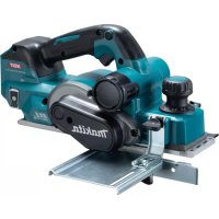
| Product Type | Electric Planer |
| Brand | MAKITA |
| Model | 1100 |
| Cutting Width | 82 mm |
| Maximum Cutting Depth | 3 mm |
| Maximum Rebate Depth | 20 mm |
| No-Load Speed | 16,000 rpm |
| Overall Length | 415 mm |
| Net Weight | 4.9 kg |
| Power Supply | Single-phase, voltage according to nameplate (double insulation) |
| Double Insulation | Yes, compliant with European standards |
| Safety Device | Safety button + trigger switch |
| Continuous Operation | With lock button |
| Front Base | Movable, height adjustable |
| Rear Base | Fixed |
| Chamfering | V-groove in the base |
| Parallel Guide | Included for rebates and guiding |
| Blade Sharpening | Sharpening holder provided |
| Brush Replacement | Carbon brushes with wear limit |
| Vacuum Compatibility | Makita vacuum via chute or deflector |
| Sound Pressure Level | 91 dB(A) |
| Sound Power Level | 102 dB(A) |
| Weighted Vibrations | ≤ 2.5 m/s² |
| Included Accessories | Parallel guide, sharpening holder, wrench |
Frequently Asked Questions - 1100 MAKITA
User questions about 1100 MAKITA
0 question about this device. Answer the ones you know or ask your own.
Ask a new question about this device
Download the instructions for your Electric planer in PDF format for free! Find your manual 1100 - MAKITA and take your electronic device back in hand. On this page are published all the documents necessary for the use of your device. 1100 by MAKITA.
USER MANUAL 1100 MAKITA
natural_image
Line drawing of hands operating a mechanical clamp or bracket assembly (no text or symbols)1
natural_image
Line drawing of hands installing or adjusting a mechanical component with a tool (no text or symbols)2
3
4
5
6
7
8
9
10
11
natural_image
Pure geometric diagram with curved lines inside a rectangle and a dashed rectangle outside (no text or symbols)12
13
14
natural_image
Line drawing of two tools mounted on a wooden plank (no text or symbols)15
natural_image
Geometric diagram showing a rectangle with curved internal lines and a dashed boundary (no text or symbols)16
17
18
natural_image
Line drawing of hands holding a device with a numbered label '33' (no text or symbols on the device itself)19
20
natural_image
Line drawing of a hand using a tool to cut a rectangular object on a textured base (no text or symbols)21
22
natural_image
Technical line drawing of a mechanical device with a curved cable and labeled component '40' (no text or symbols beyond label)23
24
25
26
27
Explanation of general view
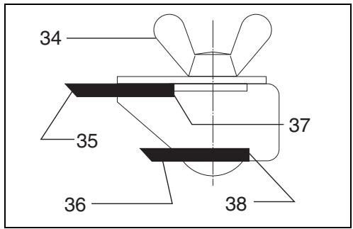
| 1 | Bolt | 18 | Mini planer blade | 34 | Wing nut |
| 2 | Drum | 19 | Hex. flange head bolt | 35 | Blade (A) |
| 3 | Planer blade | 20 | Groove | 36 | Blade (B) |
| 4 | Drum cover | 21 | Knob | 37 | Side (C) |
| 5 | Adjust plate | 22 | Switch trigger | 38 | Side (D) |
| 6 | Blade edge | 23 | Lock button/Lock-off button | 39 | European type (round) chip |
| 7 | Screws | 24 | Start | 40 | Makita vacuum cleaner |
| 8 | Heel | 25 | End | 41 | Standard (non-round) chip cover |
| 9 | Back side of gauge base | 26 | Blade edge | ||
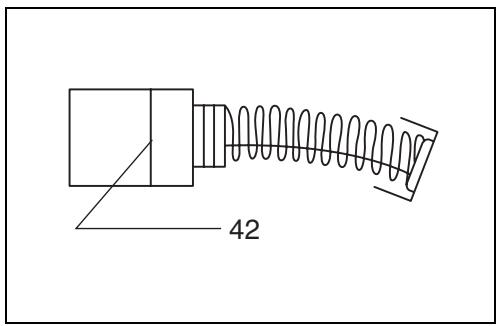
| 10 | Inside edge of gauge plate | 27 | Cutting line | 42 | Limit mark |
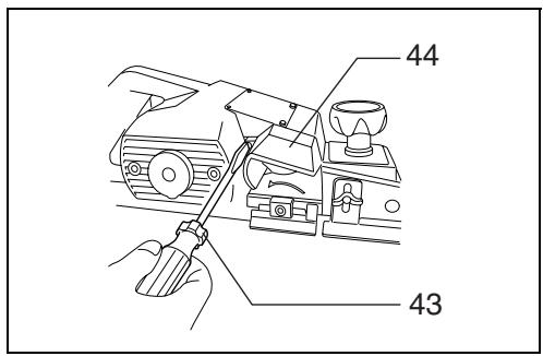
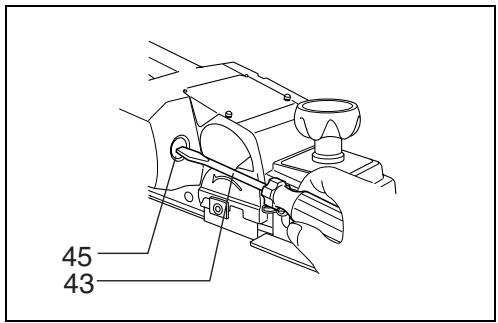
| 11 | Gauge plate | 28 | Screw | 43 | Screwdriver |
| 12 | Gauge base | 29 | Edge fence | 44 | Chip cover |
| 13 | Pan head screw | 30 | “V” groove | 45 | Brush holder cap |
| 14 | Planer blade locating lugs | 31 | Front base | ||
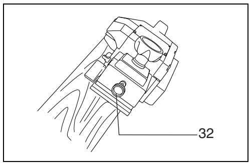
| 15 | Heel of adjust plate | 32 | Align the “V” groove with the edge of the workpiece. | ||
| 16 | Set plate | ||||
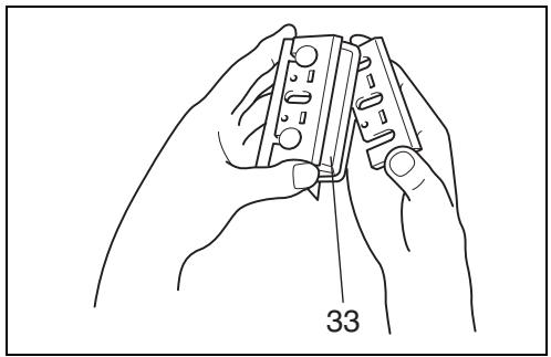
| 17 | Inside flank of gauge plate | 33 | Sharpening holder |
SPECIFICATIONS
Model 1100
Planing width 82 mm
Planing depth 3 mm
Shiplapping depth 20 mm
No load speed (RPM) 16,000
Overall length 415 mm
Net weight 4.9 kg
- Due to the continuing program of research and development, the specifications herein are subject to change without notice.
- Note: Specifications may differ from country to country.
Power supply
The tool should be connected only to a power supply of the same voltage as indicated on the nameplate, and can only be operated on single-phase AC supply. They are double-insulated in accordance with European Standard and can, therefore, also be used from sockets without earth wire.
Safety hints
For your own safety, please refer to the enclosed Safety instructions.
SPECIFIC SAFETY RULES
DO NOT let comfort or familiarity with product (gained from repeated use) replace strict adherence to planer safety rules. If you use this tool unsafely or incorrectly, you can suffer serious personal injury.
- Wait for the cutter to stop before setting the tool down. An exposed cutter may engage the surface leading to possible loss of control and serious injury.
- Use clamps or another practical way to secure and support the workpiece to a stable platform. Holding the work by hand or against your body leaves it unstable and may lead to loss of control.
- Rags, cloth, cord, string and the like should never be left around the work area.
-
Avoid cutting nails. Inspect for and remove all nails from the workpiece before operation.
-
Use only sharp blades. Handle the blades very carefully.
- Be sure the blade installation bolts are securely tightened before operation.
- Hold the tool firmly with both hands.
- Keep hands away from rotating parts.
- Before using the tool on an actual workpiece, let it run for a while. Watch for vibration or wobbling that could indicate poor installation or a poorly balanced blade.
- Make sure the blade is not contacting the workpiece before the switch is turned on.
- Wait until the blade attains full speed before cutting.
- Always switch off and wait for the blades to come to a complete stop before any adjusting.
- Never stick your finger into the chip chute. Chute may jam when cutting damp wood. Clean out chips with a stick.
- Do not leave the tool running. Operate the tool only when hand-held.
- Always change both blades or covers on the drum, otherwise the resulting imbalance will cause vibration and shorten tool life.
- Use only Makita blades specified in this manual.
- Always use the correct dust mask/respirator for the material and application you are working with.
SAVE THESE INSTRUCTIONS.
WARNING:
MISUSE or failure to follow the safety rules stated in this instruction manual may cause serious personal injury.
OPERATING INSTRUCTIONS
Removing or installing planer blades
Important:
- Always be sure that tool is switched off and unplugged before removing or installing the blade.
- Use the following planer blades.
Part Nos. 793004-6 793007-0 793322-2
A-07406 *P-04226 *P-04282
*P-04298 *820044-1 *820045-1
*820043-1
Blades with * mark are available in European countries only. Consult your dealer or the Makita Service Center when purchasing blades.
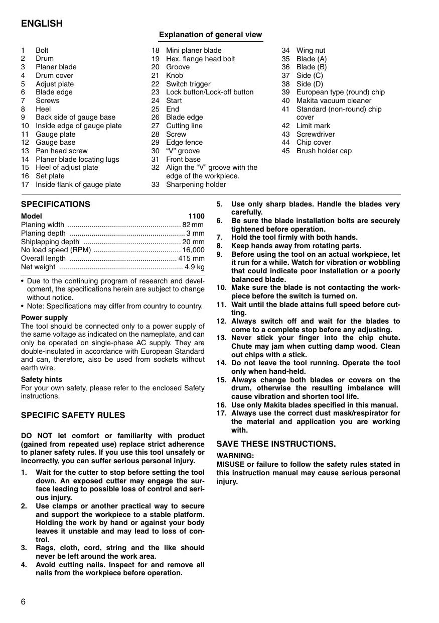
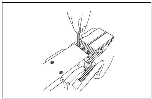
For tool with standard planer blades (Fig. 1, 3 & 4)
To remove the blades on the drum, unscrew the three installation bolts with the socket wrench. The drum cover comes off together with the blades.
To install the blades, first clean out all chips or foreign matter adhering to the drum or blades. Use blades of the same dimensions and weight, or drum oscillation/vibration will result, causing poor planing action and, eventually, tool breakdown.
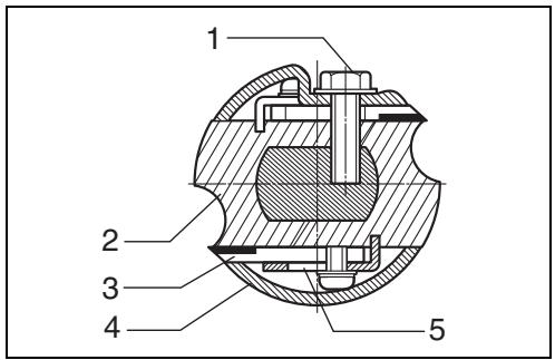
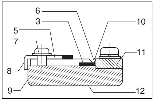
Place the blade on the gauge base so that the blade edge is perfectly flush with the inside edge of the gauge plate. Place the adjust plate on the blade, then simply press in the heel of the adjust plate flush with the back side of the gauge base and tighten two screws on the adjust plate. Now slip the heel of the adjust plate into the drum groove, then fit the drum cover on it. Tighten the three installation bolts evenly and alternately with the socket wrench.
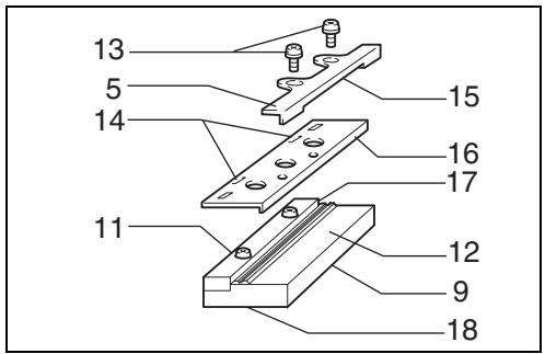
- Remove the existing blade, if the tool has been in use, carefully clean the drum surfaces and the drum cover. To remove the blades on the drum, unscrew the three installation bolts with the socket wrench. The drum cover comes off together with the blades.
- To install the blades, loosely attach the adjust plate to the set plate with the pan head screws and set the mini planer blade on the gauge base so that the cutting edge of the blade is perfectly flush with the inside flank of the gauge plate.
- Set the adjust plate/set plate on the gauge base so that the planer blade locating lugs on the set plate rest in the mini planer blade groove, then press in the heel of the adjust plate flush with the back side of the gauge base and tighten the pan head screws.
- It is important that the blade sits flush with the inside flank of the gauge plate, the planer blade locating lugs sit in the blade groove and the heel of the adjust plate is flush with the back side of the gauge base. Check this alignment carefully to ensure uniform cutting.
- Slip the heel of the adjust plate into the groove of the drum.
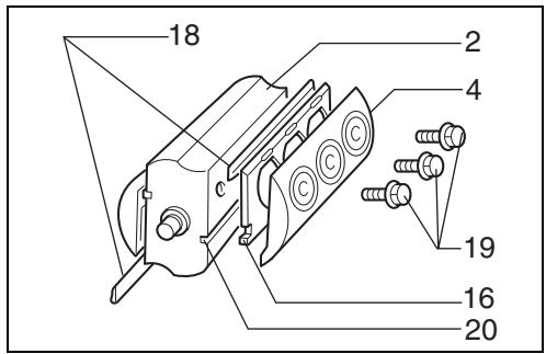
- Set the drum cover over the adjust plate/set plate and screw in the three hex flange head bolts so that a gap exists between the drum and the set plate to slide the mini planer blade into position. The blade will be positioned by the planer blade locating lugs on the set plate.
- The blade's lengthwise adjustment will need to be manually positioned so that the blade ends are clear and equidistant from the housing on one side and the metal bracket on the other.
- Tighten the three hex flange head bolts (with the socket wrench provided) and hand rotate the drum to check clearances between the blade ends and the tool body.
- Check the three hex flange head bolts for final tightness.
- Repeat procedures 1 – 9 for other blade.
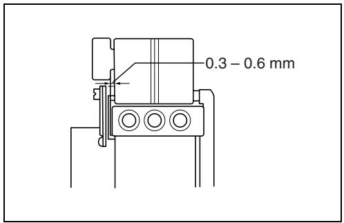
For shiplapping (Fig. 7)
The blade edge should be made to protrude outside slightly (0.3 mm – 0.6 mm). Otherwise, nicks and generally poor shiplapping results.
CAUTION:
Tighten the blade installation bolts carefully when attaching the blades to the tool. A loose installation bolt can be dangerous. Always check to see they are tightened securely.
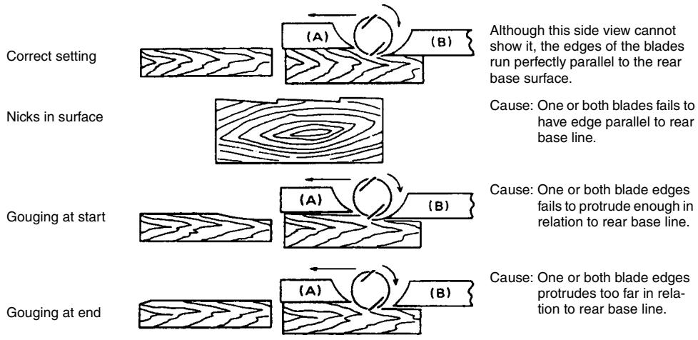
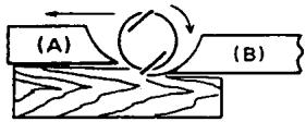
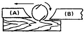
For the correct planer blade setting
Your planing surface will end up rough and uneven, unless the blade is set properly and securely. The blade must be mounted so that the cutting edge is absolutely level, that is, parallel to the surface of the rear base. Below are some examples of proper and improper settings.
(A) Front base (Movable shoe)
(B) Rear base (Stationary shoe)
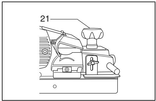
Adjusting depth of cut (Fig. 8)
Depth of cut may be adjusted by simply turning the knob on the front of the tool.
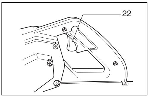
Switch action
CAUTION:
Before plugging in the tool, always check to see that the switch trigger actuates properly and returns to the "OFF" position when released.
For tool without lock button and lock-off button (Fig. 9)
To start the tool, simply pull the trigger. Release the trigger to stop.
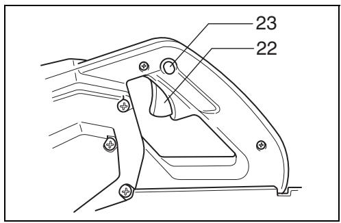
For tool with lock button (Fig. 10)
To start the tool, simply pull the trigger. Release the trigger to stop. For continuous operation, pull the trigger and then push in the lock button. To stop the tool from the locked position, pull the trigger fully, then release it.
For tool with lock-off button (Fig. 10)
To prevent the trigger from being accidentally pulled, a lock-off button is provided. To start the tool, press the lock-off button and pull the trigger. Release the trigger to stop.
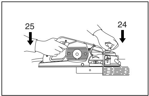
Planing operation (Fig. 11)
First, rest the tool front base flat upon the workpiece surface without the blades making any contact. Switch on and wait until the blades attain full speed. Then move the tool gently forward. Apply pressure on the front of tool at the start of planing, and at the back at the end of planing. Planing will be easier if you incline the workpiece in stationary fashion, so that you can plane somewhat downhill.
The speed and depth of cut determine the kind of finish. The power planer keeps cutting at a speed that will not result in jamming by chips. For rough cutting, the depth of cut can be increased, while for a good finish you should reduce the depth of cut and advance the tool more slowly.
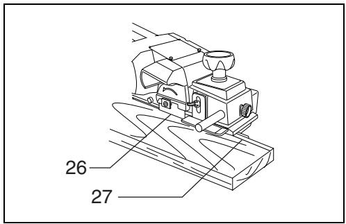
Shiplapping (Fig. 12, 13, 14 & 15)
To make a stepped cut as shown in Fig. 12, use the edge fence.
Draw a cutting line on the workpiece. Insert the edge fence into the hole in the front of the tool. Align the blade edge with the cutting line.
Adjust the edge fence until it comes in contact with the side of the workpiece, then secure it by tightening the screw.
You may wish to add to the length of the fence by attaching an extra piece of wood. Convenient holes are provided in the fence for this purpose.
NOTE:
When planing, move the tool with the edge fence flush with the side of the workpiece. Otherwise uneven planing may result. Max. shiplapping depth is 20 mm.
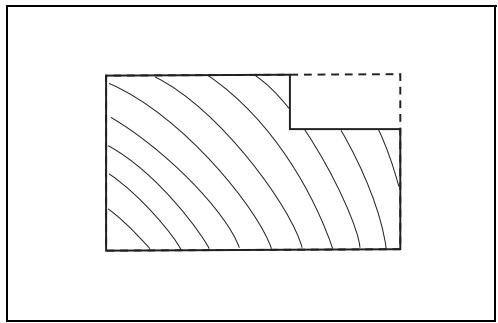
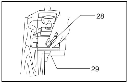
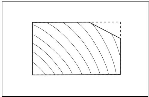
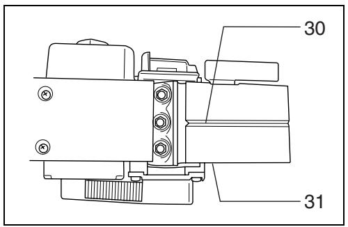
Chamfering (Fig. 16, 17 & 18)
To make a cut as shown in Fig. 16, align the "V" groove in the front base with the edge of the workpiece and plane it as shown in the Fig. 18.
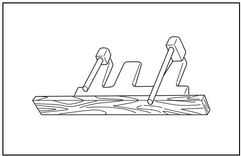
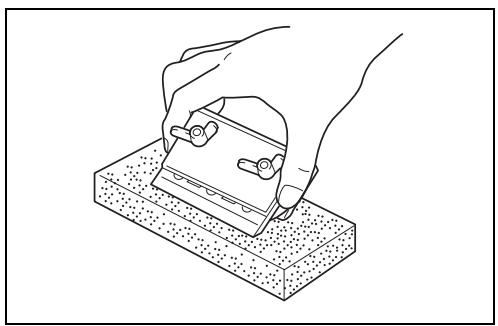
Sharpening planer blades (Fig. 19, 20 & 21)
For standard blades only
Always keep your blades sharp for the best performance possible. Use the sharpening holder to remove nicks and produce a fine edge.
First, loosen the two wing nuts on the holder and insert the blades (A) and (B), so that they contact the sides (C) and (D). Then tighten the wing nuts.
Immerse the dressing stone in water for 2 or 3 minutes before sharpening. Hold the holder so that the blades both contact the dressing stone for simultaneous sharpening at the same angle.
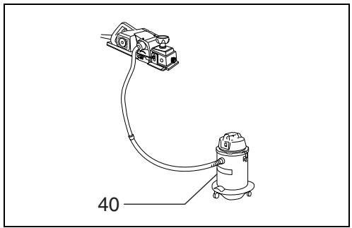
Connecting a vacuum cleaner
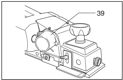
For tool with European type (round) chip cover (Fig. 22 & 23)
When you wish to perform clean planing operation, connect a Makita vacuum cleaner to your tool as shown in Fig. 23.
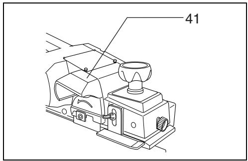
For tool with standard (non-round) chip cover (Fig. 24)
Any Makita vacuum cleaner cannot be connected to the tool with the standard (non-round) chip cover.
MAINTENANCE
CAUTION:
Always be sure that the tool is switched off and unplugged before carrying out any work on the machine.
Replacement of carbon brushes (Fig. 25, 26 & 27)
Replace carbon brushes when they are worn down to the limit mark. First, remove the chip cover and then replace the carbon brushes. Both identical carbon brushes should be replaced at the same time.
To maintain product safety and reliability, repairs, maintenance or adjustment should be carried out by Makita Authorized Service Center.
ACCESSORIES
CAUTION:
These accessories or attachments are recommended for use with your Makita tool specified in this manual. The use of any other accessories or attachments might present a risk of injury to persons. Only use accessory or attachment for its stated purpose.
If you need any assistance for more details regarding these accessories, ask your local Makita service center.
- Planer blade (2 per pkg.)
- Sharpening holder assembly
- Dressing stone
- Blade gauge assembly
- Socket wrench
- Edge fence (guide rule)
- Dust bag assembly
- Planer stand
- Tungsten carbide tipped mini planer blade (2 per pkg.)
Descriptif
natural_image
Abstract line drawing of concentric contour lines within a rectangular boundary (no text or symbols)Afiar as lâminas de corte (Fig. 19, 20 e 21)
natural_image
Abstract line drawing of a tree with concentric contour lines (no text or symbols)Κοίλωμα στην αρχή

Κοίλωμα στο τέλος

EC-DECLARATION OF CONFORMITY
We declare under our sole responsibility that this product is in compliance with the following standards of standardized documents,
EN60745, EN55014, EN61000
in accordance with Council Directives, 89/336/EEC and 98/37/EC.
FRANÇAISE
DÉCLARATION DE CONFORMITÉ CE
Michigan Drive, Tongwell, Milton Keynes, Bucks MK15 8JD, ENGLAND
Responsible manufacturer:
Fabricant responsible :
EU-DEKLARATION OM KONFORMITET
Michigan Drive, Tongwell, Milton Keynes, Bucks MK15 8JD, ENGLAND
For European countries only
Noise and Vibration
The typical A-weighted noise levels are sound pressure level: 91 dB (A) sound power level: 102 dB (A) Uncertainty is 3 dB (A). - Wear ear protection. -
The typical weighted root mean square acceleration value is not more than 2.5 m/s^2 .
These values have been obtained according to EN60745.
FRANÇAISE


- SPECIFICATIONS
- Power supply
- Safety hints
- SPECIFIC SAFETY RULES
- SAVE THESE INSTRUCTIONS.
- WARNING:
- OPERATING INSTRUCTIONS
- Removing or installing planer blades
- For tool with standard planer blades (Fig. 1, 3 & 4)
- For shiplapping (Fig. 7)
- CAUTION:
- For the correct planer blade setting
- Adjusting depth of cut (Fig. 8)
- Switch action
- For tool without lock button and lock-off button (Fig. 9)
- For tool with lock button (Fig. 10)
- For tool with lock-off button (Fig. 10)
- Planing operation (Fig. 11)
- Shiplapping (Fig. 12, 13, 14 & 15)
- NOTE:
- Chamfering (Fig. 16, 17 & 18)
- Sharpening planer blades (Fig. 19, 20 & 21)
- For standard blades only
- Connecting a vacuum cleaner
- For tool with European type (round) chip cover (Fig. 22 & 23)
- For tool with standard (non-round) chip cover (Fig. 24)
- MAINTENANCE
- Replacement of carbon brushes (Fig. 25, 26 & 27)
- ACCESSORIES
- Afiar as lâminas de corte (Fig. 19, 20 e 21)
- EC-DECLARATION OF CONFORMITY
- FRANÇAISE
- DÉCLARATION DE CONFORMITÉ CE
- EU-DEKLARATION OM KONFORMITET
- For European countries only
- Noise and Vibration
Brand : MAKITA
Model : 1100
Category : Electric planer