
CGL6V17IX - Range hood VOX - Free user manual and instructions
Find the device manual for free CGL6V17IX VOX in PDF.


| Product Type | Wall-mounted cooker hood |
| Brand | VOX |
| Model | CGL6V17IX |
| Installation Type | Ducted (external exhaust) or recirculation (with charcoal filter) |
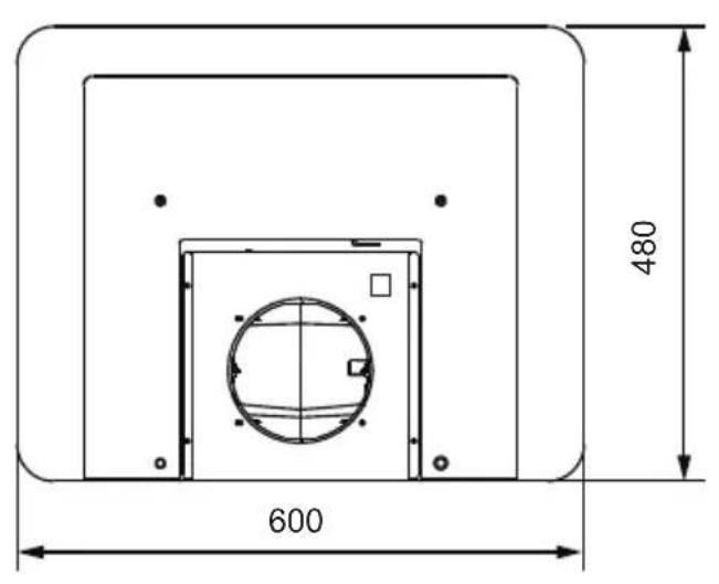
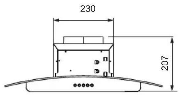
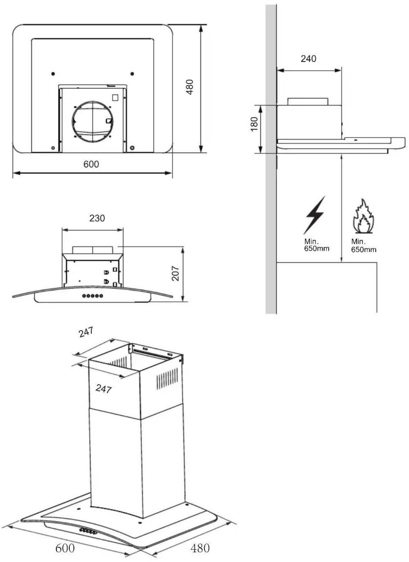
| Dimensions (W x D) | 600 mm x 480 mm |
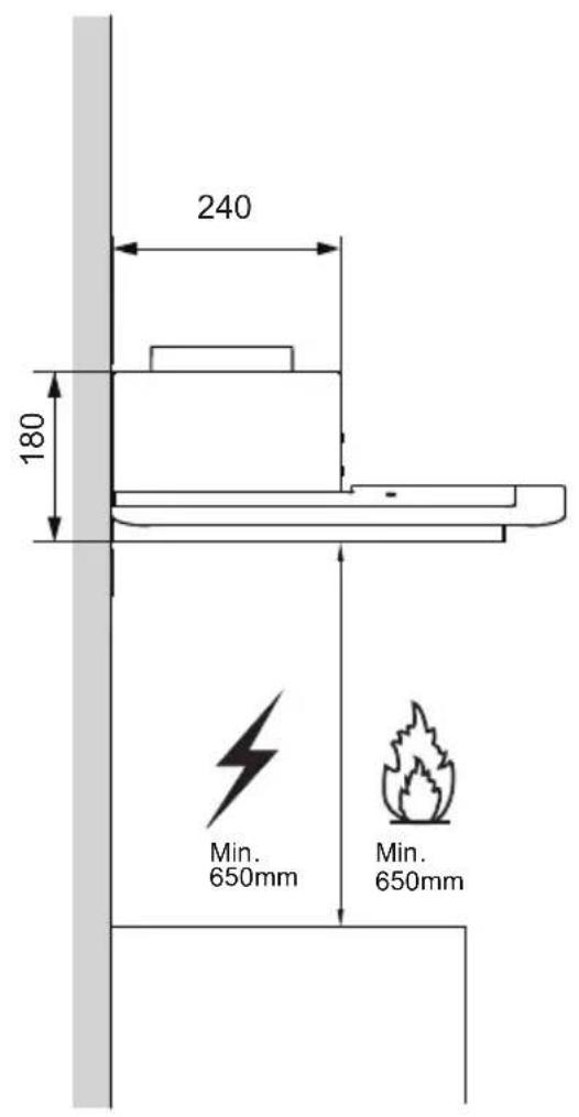
| Min. Distance from Gas Hob | 650 mm |
| Motor Speeds | Low, Medium, High |
| Control Type | Buttons |
| Lighting Type | Self-ballasted LED modules |
| Lighting Power | 1.5 W |
| Lighting Voltage | 220-240 V |
| Grease Filter Type | Metal self-supporting |
| Grease Filter Cleaning | Every 2 months, washable in dishwasher |
| Charcoal Filter | Optional, for recirculation mode; replace every 4 months |
| Ducting Diameter | 120 mm or 150 mm |
| Power Supply | 220-240 V, 50/60 Hz (assumed) |
| Max. Number of Hob Elements | 4 |
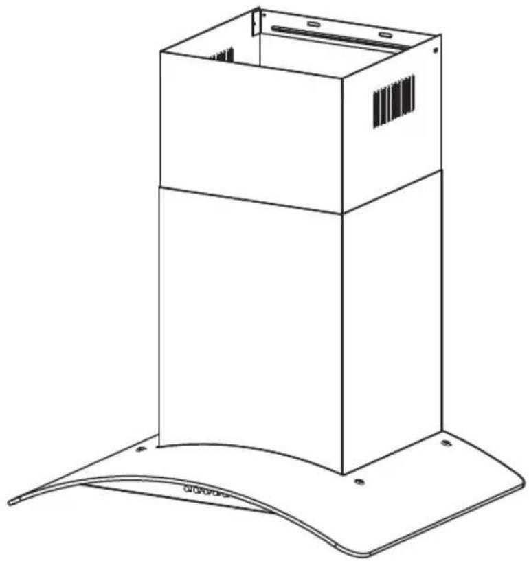
| Included Components | Hood body, lower/upper chimney, exhaust pipe, flange, fixing kit, instruction manual |
| Safety Features | Class I appliance, requires earthing; minimum distance from hob; not for commercial use |
Frequently Asked Questions - CGL6V17IX VOX
User questions about CGL6V17IX VOX
0 question about this device. Answer the ones you know or ask your own.
Ask a new question about this device
Download the instructions for your Range hood in PDF format for free! Find your manual CGL6V17IX - VOX and take your electronic device back in hand. On this page are published all the documents necessary for the use of your device. CGL6V17IX by VOX.
USER MANUAL CGL6V17IX VOX
natural_image
Line drawing of a rectangular box with a curved base and mounting feet, no text or symbols presentCOOKER HOOD
INSTRUCTION MANUAL
Read this manual carefully before operation
Pictures in this manual are for reference only, the product in kind prevail.

The instructions for Use apply to several versions of this appliance. Accordingly, you
may find descriptions of individual features that do not apply to your specific appliance.
INSTALLATION
● The manufacturer will not be held liable for any damages resulting from incorrect or improper installation.
- The minimum distance between the supporting surface for the cooking vessels on the hob and the lowest part of the range hood. ( When the range hood is located above a gas appliance, this distance shall be at least 65 cm. If the instructions for installation for the gas hob specify a greater distance, this has to be taken into account. The distance of 65 cm can be reduced for:non-combustible parts of range hoods, and parts operating at safety extra low voltage,Provided these parts do not give access to live parts if deformed;)
- Check that the mains voltage corresponds to that indicated on the rating plate fixed to the hood.
- For Class I appliances, check that the domestic power supply guarantees adequate earthing.
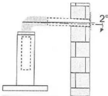
- Connect the extractor to the exhaust flue through a pipe of minimum diameter 120mm. The route of the flue must be as short as possible.
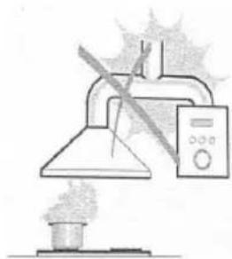
● The air must not be discharged into a flue that is used for exhausting fumes from appliances burning gas or other fuels.
- If the extractor is used in conjunction with non-electrical appliances (e.g. gas burning appliances), a sufficient degree of aeration must be guaranteed in the room in order to prevent the backflow of exhaust gas. The kitchen must have an opening communicating directly with the open air in order to guarantee the entry of clean air.
- When the cooker hood is used in conjunction with appliances supplied with energy other than electric, the negative pressure in the room must not exceed 0.04 mbar to prevent fumes being drawn back into the room by the cooker hood.
- If the supply cord is damaged, it must be replaced by the manufacturer, its service agent or similarly qualified persons in order to avoid a hazard.
● Regulations concerning the discharge of air have to be fulfilled.
natural_image
Simple line drawing of a laboratory setup with a conical flask, thermometer, and smokestack (no text or symbols)USE
● The cooker hood is only for home use, not suitable for barbecue, roast shop and other commercial purposes.
● Never use the hood for purposes other than for which it has been designed.
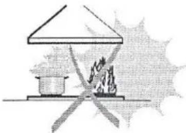
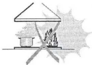
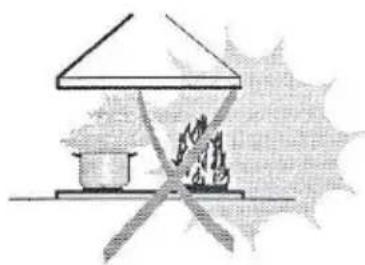
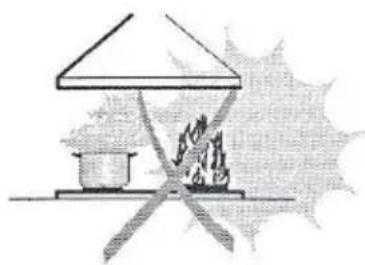
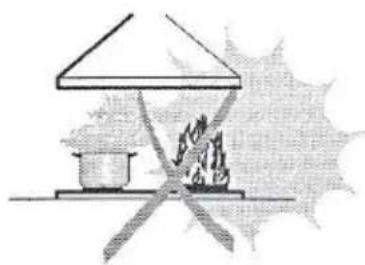
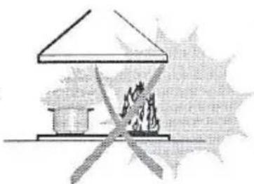
● Never leave high naked flames under the hood when it is in operation.
- Adjust the flame intensity to direct it onto the bottom of the pan only, making sure that it does not engulf the sides.
- Deep fat fryers must be continuously monitored during use: overheated oil can burst into flames.
● Do not flame under the range hood; risk of fire.
- This appliance can be used by children aged from 8 years and above and persons with reduced physical, sensory or mental capabilities or lack of experience and knowledge if they have been given supervision or instruction concerning use of the appliance in a safe way and understand the hazards involved.
● Children should be supervised to ensure that they do not play with the appliance.
● Cleaning and user maintenance shall not be made by children without supervision.
● "CAUTION: Accessible parts may become hot when used with cooking appliances".
MAINTENANCE
● The cooker hood and its filter should be cleaned regularly according to the instruction.
- Switch off or unplug the appliance from the mains supply before carrying out any maintenance work.
● Clean and/or replace the Filters after the specified period(Fire hazard).
● Clean the hood using a damp cloth and a neutral liquid detergent.
● The appliance uses 4 hob elements at most.
natural_image
Simple line drawing of a house with a pot and fire, no text or symbols present
The symbol is packaging indicates that this product may not be treated as household waste. Instead it shall be handed over to the applicable collection point for the recycling of electrical and electronic equipment. By ensuring this product is disposed of correctly, you will help prevent potential negative consequences for the environment and human health, which could otherwise be caused by inappropriate waste handling of this product. For more detailed information about recycling of this product, please contact your local city office, your household waste disposal service or the shop where you purchased the product.
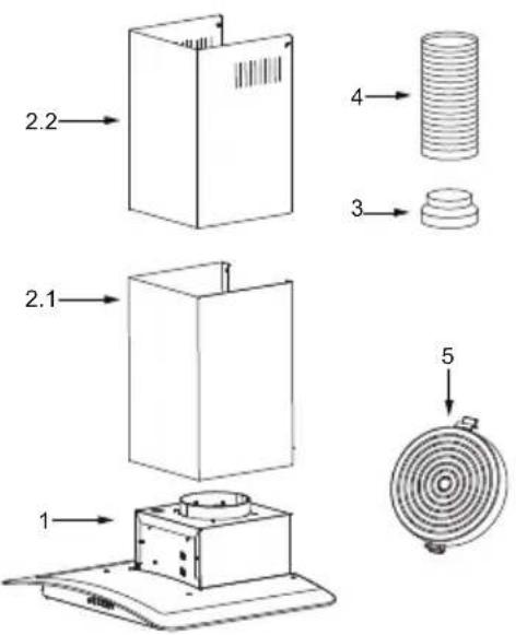
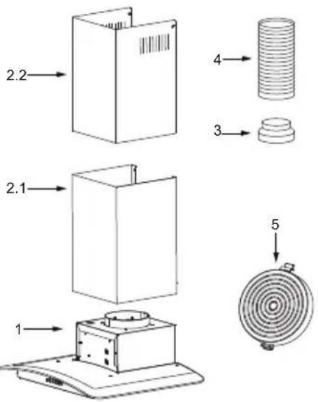
| Ref. Qty. | Product Components | |
| 1 | 1 | Hood Body,complete with: Controls, Light, Blower,Filter. |
| 2.1 | 1 | Lower Decorative Chimney |
| 2.2 | 1 | Upper Decorative Chimney |
| 3 | 1 | Flange ( optional ) |
| 4 | 1 | Exhaust Pipe |
| 5 | 2 | The Activated Charcoal filter ( optional ) |
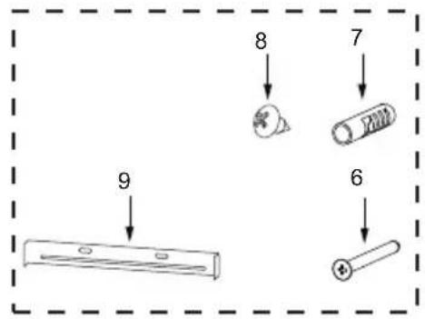
| Ref. Qty. Installation Components | |
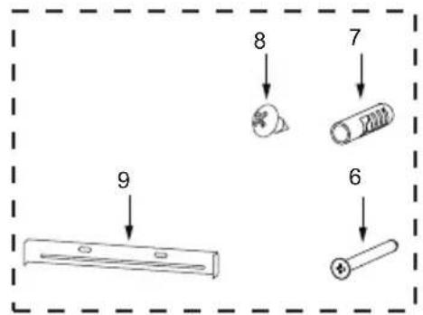
| 6 | 7 Screws 5 x 50 |
| 7 | 7 Wall Plugs |
| 8 | 6 Screws 4.2 x 9.5 |
| 9 | 2 Chimney fixing bracket |
| Qty. Documentation |
| 1 Instruction Manual |
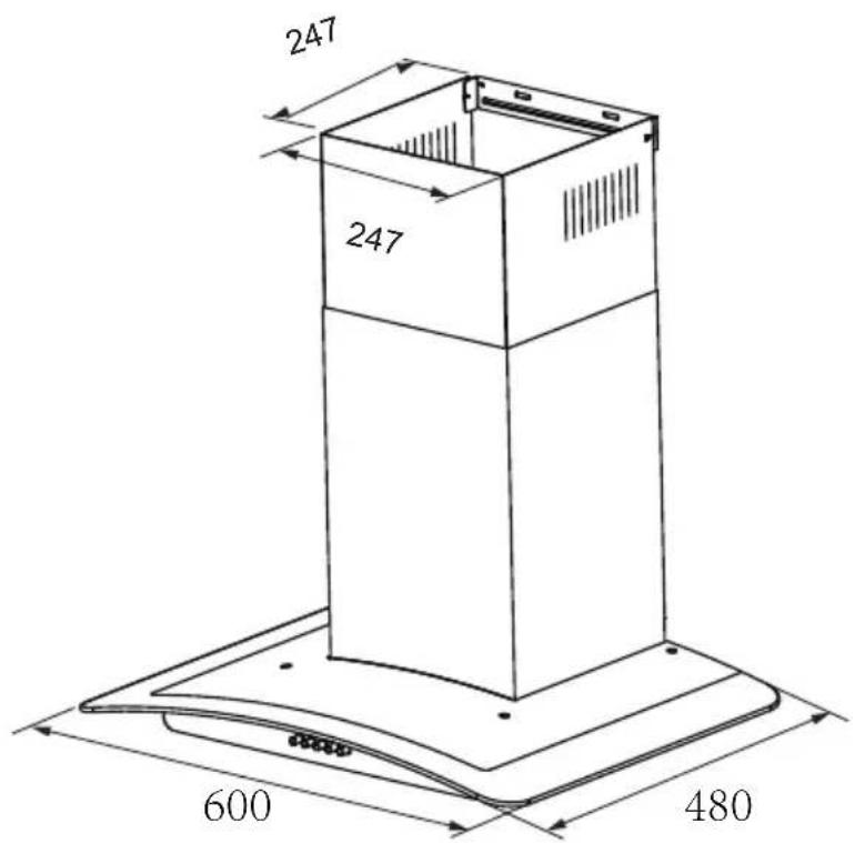
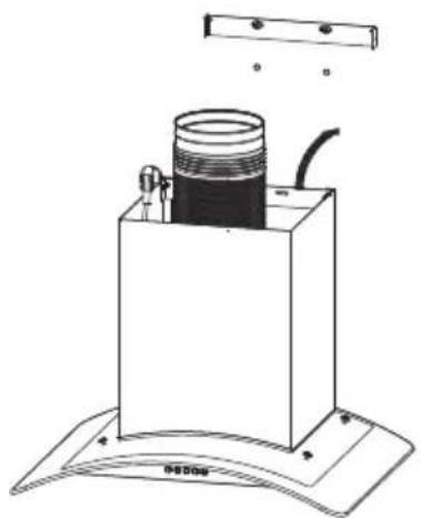
WALL DRILLING AND BRACKET FIXING
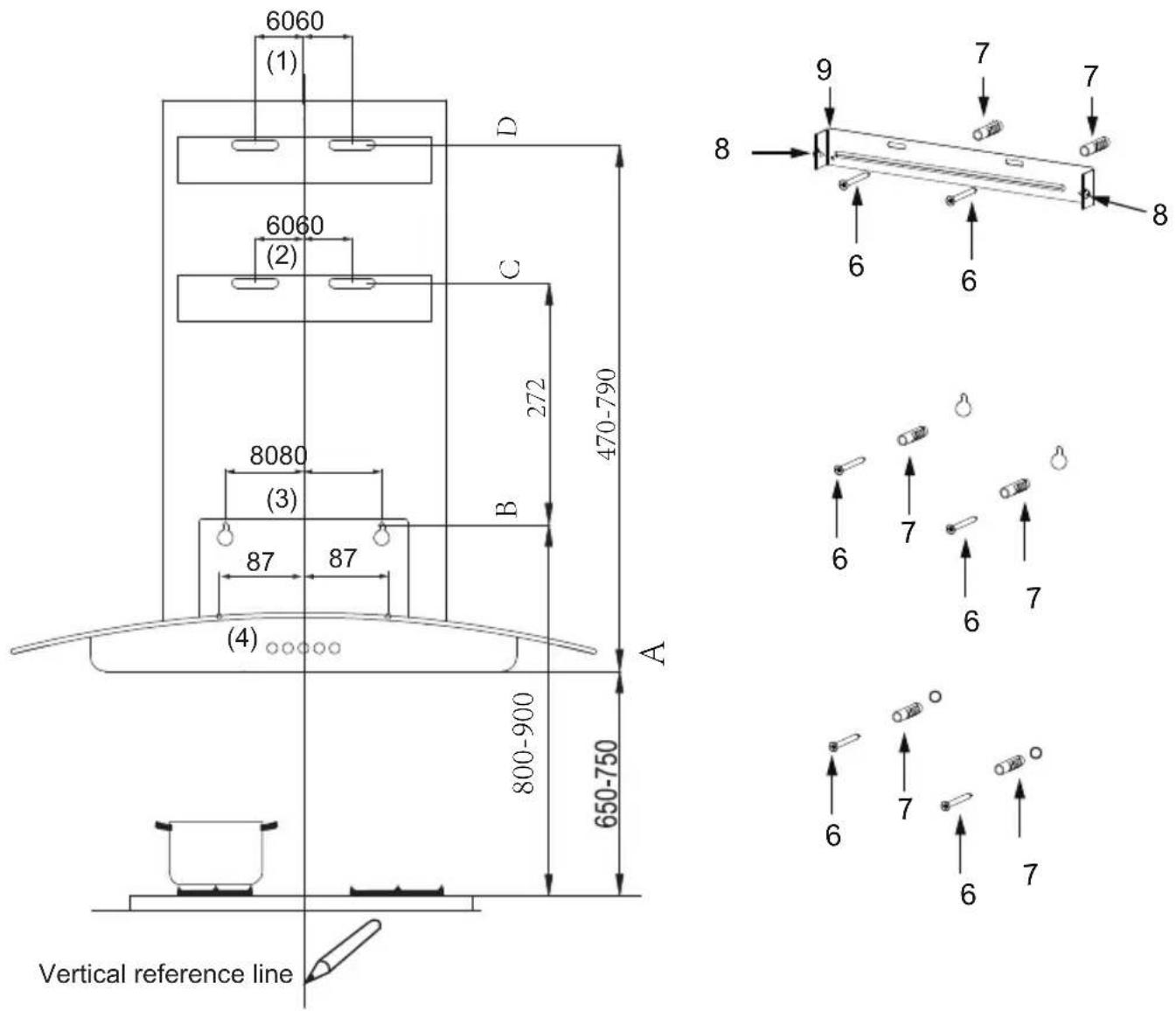
As a first step, proceed with the following drawings:
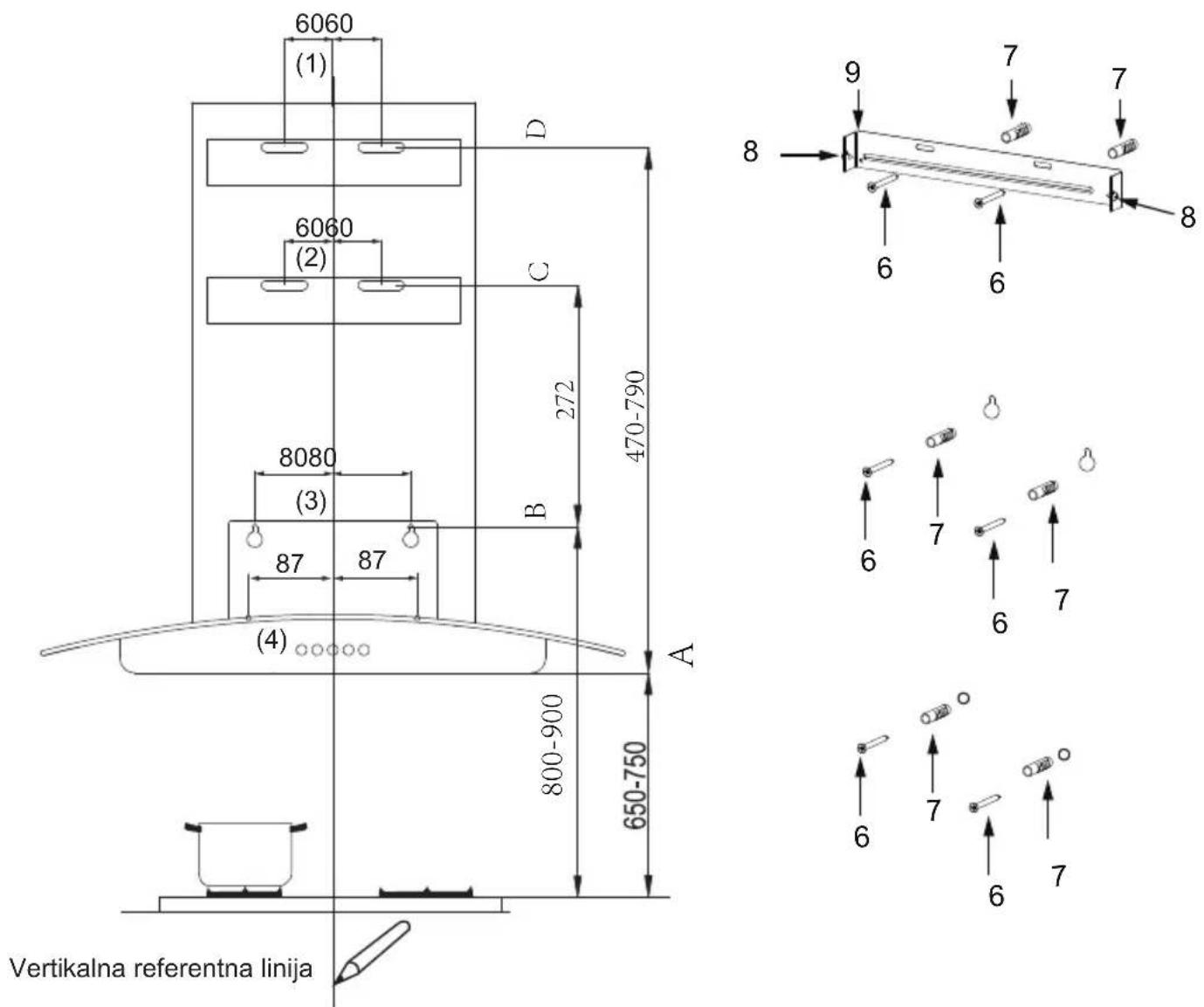
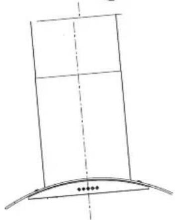
- A vertical line up to the ceiling or up to the upper limit, at the center of the area in which the hood is to be fitted.
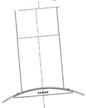
- The cooker hood should be placed 650-750 mm (horizontal line A) up from the cooking plane for safe and a good effect.
● A horizontal line B at a minimum 800-900 mm above the cooker top.
● A horizontal line C at a 272 mm above the B.
● A horizontal line D at 470-790 mm above the cooker hood.
Mark Points:
● Mark a point (1) on the horizontal line D, 60 mm to the vertical reference line.
- Repeat this operation on the other side, checking that the three marks are leveled.
● Mark a point (2) on the horizontal line C, 60 mm to the vertical reference line.
- Repeat this operation on the other side, checking that the three marks are leveled.
● Mark a point (3) on the horizontal line B, 80 mm to the vertical reference line.
- Repeat this operation on the other side, checking that the three marks are leveled.
Fix the brackets:
● Drill holes at the marked points with a 10 mm drill bit. Insert the
● Wall Plugs 7 into the holes.
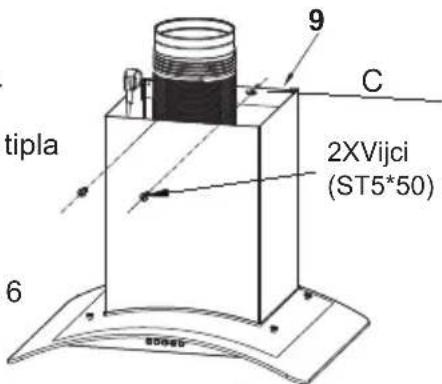
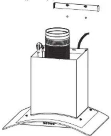
● Fix the Screws (5 x 50) bracket 6 with 2 screws supplied with the hood at the horizontal line B.
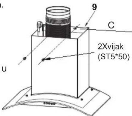
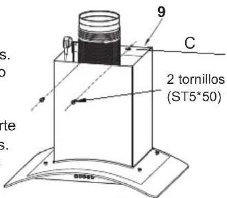
● Chimney fixing bracket 9 with 2 screws 6 (ST5x50) supplied with the hood at the horizontal line D.
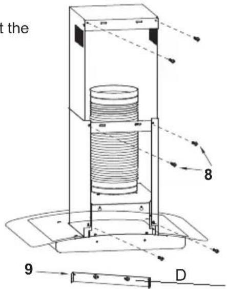
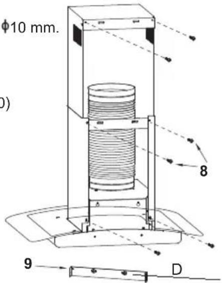
Fix lower decorative chimney
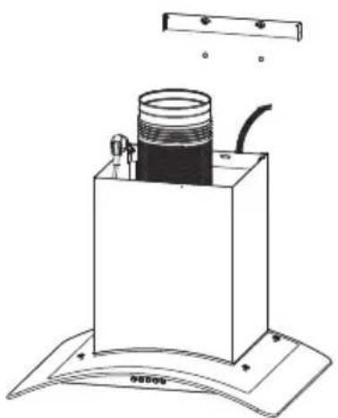
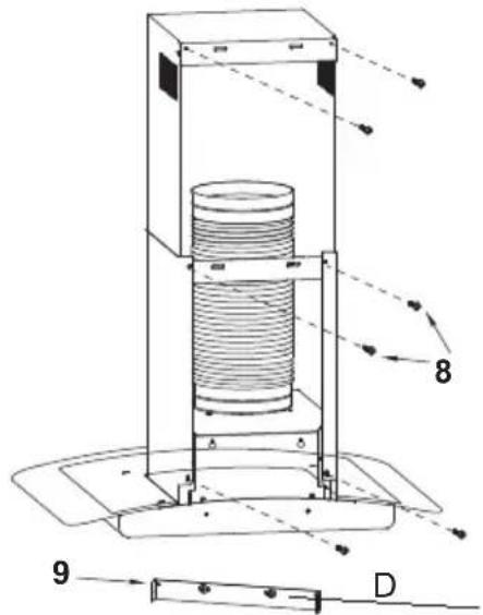
● Fix the exhaust pipe on the hood body.
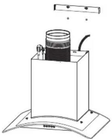
- Connect chimney and hood body with 2 screws 8.
- Connect chimney fixing bracket 9 and chimney with 2 screws 8.
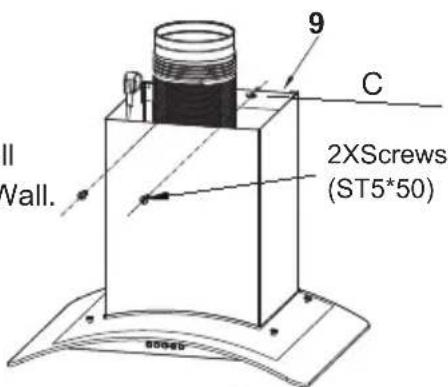
Hook the hood body
● To mount on the wall, drill two 10mm.
- Insert two plastics wall plugs(supplied) into the holes.
- Insert two screws (ST5*50) 6 into the upper two plastic wall plugs, and tighten them leaving 3mm , protruding from the Wall.
- Mount the hood on the top screws, Insert the bottom screws and fully tighten all the screws.
- Remove the filter from the inside of the hood body, fix the screws 6 to Wall Plugs 7 at the points (4).
natural_image
Technical line drawing of a mechanical device with a cylindrical component and mounting base (no text or symbols)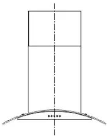
natural_image
Pure geometric diagram showing a vertical rectangle above a curved base with dots at the base (no text or symbols)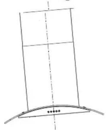
natural_image
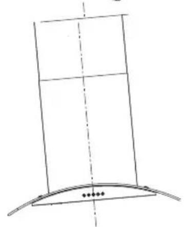
Simple line drawing of a curved structure with a vertical panel and dashed centerline (no text or symbols)Right Wrong
CONNECTIONS
DUCTED VERSION AIR EXHAUST SYSTEM
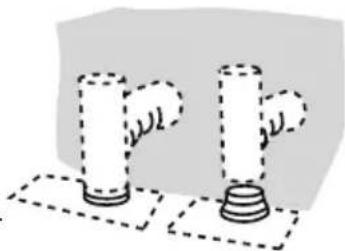
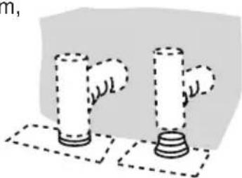
When installing the ducted version, connect the hood to the chimney using either a flexible or rigid pipe 150 or 120 mm, the choice of which is left to the installer.
- If to install a 120 mm air exhaust connection, insert the reducer flange 3 on the hood body outlet.
● Fix the pipe 4 in position using sufficient pipe clamps (not supplied). - Remove possible charcoal filters.
natural_image
Two cylindrical objects with dashed outlines, one larger and one smaller, placed on a flat surface (no text or symbols)Upper Decorative Chimney
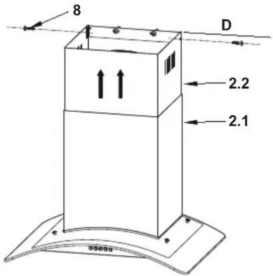
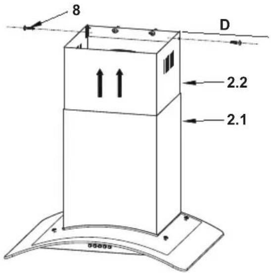
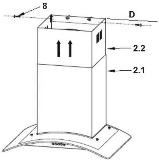
- Insert the upper decorative chimney 2.2 into the lower decorative chimney 2.1 and drag it up to the horizontal line D.
- Connect upper decorative chimney 2.2 and chimney fixing bracket 9 with 2 screws 8.
USE
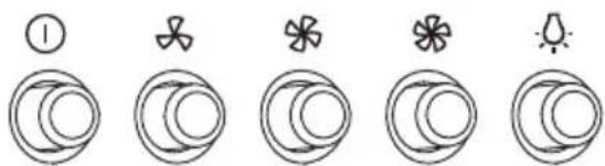
Speed adjustment. (For some models)
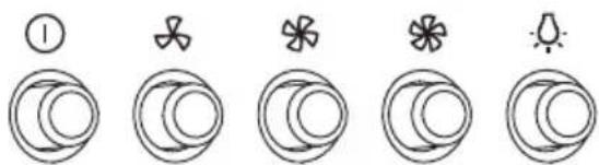
| 1 | OFF MOTOR SWITCH: Press on this switch to stop the motor operation. |
| SPEED SWITCH: Press on this switch, the motor runs at LOW speed. | |
| SPEED SWITCH: Press on this switch, the motor runs at MEDIUM speed. | |
| SPEED SWITCH: Press on this switch, the motor runs at HIGH speed. | |
| ON/OFF LIGHTING SWITCH: Press on this switch to turn on the lights, and press again to turn them off. |
GREASE FILTERS
CLEANING METAL SELF-SUPPORTING GREASE FILTERS
- The filters must be cleaned every 2 months of operation, or more frequently for particularly heavy usage, and can be washed in a dishwasher.
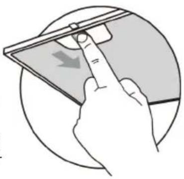
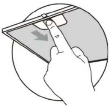
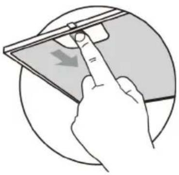
● Pull the comfort panels to open them. - Remove the filters one by one pushing them towards the back side of the hood unit and simultaneously pulling downwards.
- Any kind of bending of the filters has to be avoided when washing them. Before fitting them again into the hood make sure that they are completely dry. (The color of the filter surface may change throughout the time but this has no influence to the filter efficiency).
- When fitting the filters into the hood pay attention that they are mounted in correct position the handle facing outwards.
natural_image
Illustration of a hand pressing down on a device screen with a downward arrow (no text or symbols)ACTIVATED CHARCOAL FILTER (RECIRCULATION VERSION)
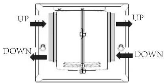
These filters are not washable and cannot be regenerated, and must be replaced approximately every 4 months of operation, or more frequently with heavy usage.
REPLACING THE ACTIVATED CHARCOAL FILTER
- Remove the metal grease filters.
- Remove the saturated activated charcoal filter.
- Fit the new filters.
- Replace the metal grease filters.
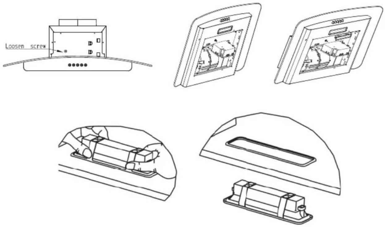
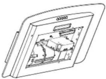
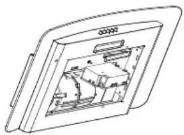
LIGHT REPLACEMENT
Replacing the light modules
Disconnect the power supply
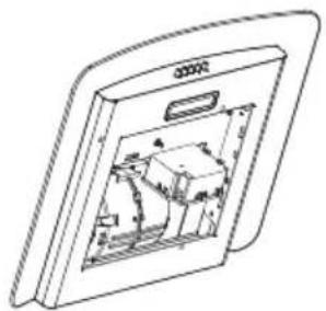
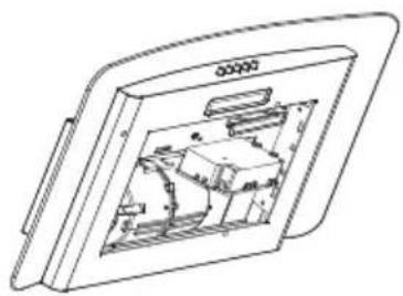
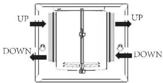
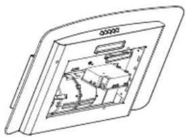
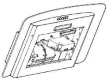
Loosen Screw Take out the junction box Take out Led
| Max power | Voltage Picture | Lamp Cap ILCOS D code | |||
| Self-ballasted LED modules | 1.5W 220V-240V | 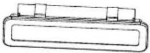 Square/Diameter:33.2mmx120mm Square/Diameter:33.2mmx120mm | / | DBS-1.5-H-33.2/120 | |
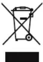
The European directive 2012/19/EU on Waste Electrical and Electronic Equipment (WEEE), requires that old household electrical appliances must not be disposed of in the normal unsorted municipal waste stream. Old appliances must be collected separately in order to optimize the recovery and recycling of the materials they contain, and reduce the impact on human health and the environment.
The crossed out “wheeled bin” symbol on the product reminds you of your obligation, that when you dispose of the appliance, it must be separately collected.
Consumers should contact their local authority or retailer for information concerning the correct disposal of their old appliance.
| Fault Cause | Use Solution | |
| Light on, but motor does not work | The blades are blocked. | Check the blades. |
| The capacitor is damaged. Replace capacitor. | ||
| The motor is damaged. Replace motor. | ||
| The internal wiring of motor is cut off/disconnected. An unpleasant smell may be produced. | Replace motor. | |
| Both light and motor do not work | Apart from the above mentioned, check the following: | |
| Light damaged. Replace lights. | ||
| Power cord loose. | Connect the wires as the electric diagram. | |
| Oil leakage | Outlet and the air ventilation entrance are not tightly sealed. | Take down the outlet and seal with glue. |
| Vibration | The blade, if damaged, can cause vibrating. | Replace the blade. |
| The motor is not tightly fastened. Fasten the motor tightly. | ||
| The cooker hood is not tightly fixed. Fixed the cooker hood tightly. | ||
| Insufficient suction | The distance between the cooker hood and the cooker top is too large. | Readjust the distance. |
| Too much ventilation from open doors or windows. | Choose a new place to install the appliance or close some doors / windows. | |
| The machine inclines | The fixing screws are not tight enough. | Tighten the fixing screw and make it horizontal. |
| The hanging screws are not tight enough | Tighten the hanging screw and make it horizontal. | |

CGL6V17IX
CGL6V17BL
natural_image
Line drawing of a rectangular box mounted on a curved base, with no visible text or symbols.ASPIRATOR
UPUTSTVO ZA UPOTREBU
Pre upotrebe proizvoda pažljivo pročitajte uputstvo
Slike u ovom uputstvu su samo za referencu, stvarni izgled proizvoda ima prednost.

natural_image
Simple line drawing of a laboratory setup with a lamp, control panel, and heating element (no text or symbols)UPOTREBA
ODRŽAVANJE
- Aspirator i filter treba redovno čistiti prema uputstvima.
- Isključite utikač uređaja iz električne utičnice pre čišćenja uređaja.
- Očistite haubu aspiratora koristeći vlažnu krpu i neutralni tečni deterdžent.
- Uređaj koristi maksimalno 4 grejne zone na šporetu.
natural_image
Simple line drawing of a house with a chimney and a cooking pot, no text or symbols present
Simbol na ambalaži ukazuje na to da se ovaj proizvod ne sme tretirati kao kućni otpad. Umesto toga, treba ga predati odgovarajućem sakupljalištu za recikliranje električne i elektronske opreme. Osiguravajući pravilno odlaganje ovog proizvoda, pomažete sprečavanju potencijalno negativnih posledica po životnu sredinu i ljudsko zdravlje, koje bi inače mogle nastati usled neadekvatnog rukovanja otpadom ovog proizvoda. Za detaljnije informacije o reciklaži ovog proizvoda, obratite se lokalnoj gradskoj upravi, službi za odlaganje kućnog otpada ili prodavnici u kojoj ste kupili proizvod.
Br. Kol. Delovi proizvoda
| 1 | 1 | Telo aspiratora, zajedno sa: kontrolama, svetlom, ventilatorom, filterom. |
| 2.1 | 1 | Donji dekorativni dimnjak |
| 2.2 | 1 | Gornji dekorativni dimnjak |
| 3 | 1 | Flanša ( optiono ) |
| 4 | 1 | Izduvna cev |
| 5 | 2 | Aktivni ugljeni filter ( optiono ) |
Br. Kol. Delovi za instalaciju
| 6 | 7 Vijci 5 x 50 |
| 7 | 7 Tiplovi za zid |
| 8 | 6 Vijci 4.2 x 9.5 |
| 9 | 2 Nosač za fiksiranje dimnjaka |
Kol. Dokumentacija
| 1 | Uputstvo za upotrebu |
flowchart
graph TD
    A["6"] --> B["7"]
    B --> C["8"]
    C --> D["9"]
BUŠENJE ZIDA I MONTAŽA NOSAČA
natural_image
Technical line drawing of a mechanical device with a cylindrical component and mounting base (no text or symbols)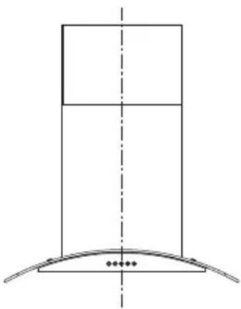
natural_image
Pure technical diagram showing a vertical structure with a curved base and dashed centerline (no text or symbols)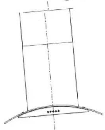
natural_image
Simple line drawing of a vertical structure with a curved base and dashed vertical line, no text or symbols present.Ispravno
Pogrešno
POVEZIVANJE
ASPIRATOR SA IZDUVNIM SISTEMOM
Prilikom instalacije izduvnog aspiratora, povežite aspirator sa dimnjakom koristeći fleksibilnu ili krutu cev prečnika φ 150 ili φ 120 mm, a izbor zavisi od instalatera.
- Da biste instalirali priključak za odvod vazduha od 120 mm, umetnite prirubnicu reduktora 3 na izlaz kućišta aspiratora.
- Pričvrstite cev koristeći stezaljke za cev (nisu isporučene).
- Uklonite moguće ugljene filtere.
natural_image
Two cylindrical objects with dashed outlines, one larger and one smaller, placed on a base (no text or symbols)Gornji dekorativni dimnjak
- Umetnite gornji dekorativni dimnjak 2.2 u donji dekorativni dimnjak 2.1 i prevucite ga nagore do horizontalne linije D.
- Povežite gornji dekorativni dimnjak 2.2 i držač za pričvršćivanje dimnjaka 9 sa 2 zavrtnja 8.
UPOTREBA
Prilagođavanje brzine. (Za neke modele)
| 1 | PREKIDAČ ZA ISKLJUČIVANJE MOTORA: Pritisnite ovaj prekidač da zaustavite rad motora. |
| PREKIDAČ BRZINE: Pritisnite ovaj prekidač, motor će raditi na NISKOJ brzini. | |
| PREKIDAČ BRZINE: Pritisnite ovaj prekidač, motor će raditi na SREDNJOJ brzini. | |
| PREKIDAČ BRZINE: Pritisnite ovaj prekidač, motor će raditi na VISOKOJ brzini. | |
| PREKIDAČ ZA UKLJUČIVANJE/ISKLJUČIVANJE SVETLA: Pritisnite ovaj prekidač da uključite svetla i ponovo pritisnite da ih isključite. |
FILTERI ZA MASNOĆU
ČIŠĆENJE METALNIH SAMONOSEĆIH FILTERA ZA MASNOĆU
- Filtere treba čistiti svaka 2 meseca rada, ili češće ukoliko je upotreba posebno intenzivna, i mogu se prati u mašini za pranje sudova.
● Povucite panel da biste otvorili. - Izvucite filtere jedan po jedan gurajući ih prema zadnjem delu aspiratora i istovremeno ih povlačeći nadole.
- Prilikom pranja, izbegavajte savijanje filtera. Pre nego što ih ponovo postavite u aspirator, uverite se da su potpuno suvi. (Boja površine filtera može se promeniti tokom vremena, ali to ne utiče na efikasnost filtera).
- Prilikom postavljanja filtera u aspirator, obratite pažnju da su montirani u pravilnom položaju, sa ručkom okrenutom prema spolja.
natural_image
Illustration of a hand pressing down on a tablet device (no text or symbols visible)AKTIVNI UGLJENI FILTER (VERZIJA SA RECIRKULACIJOM)
ZAMENA SIJALICE
Zamena svetlosnih modula
natural_image
Line drawing of a rectangular box mounted on a curved base, with no visible text or symbols.KUHINJSKA NAPA
NAVODILA ZA UPORABO
natural_image
Simple line drawing of a laboratory setup with a conical flask, heating a test tube, and a control panel (no text or symbols)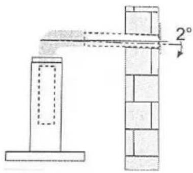
natural_image
Simple line drawing of a house with a stove and fire, no text or symbols presentnatural_image
Technical line drawing of a mechanical device with a cylindrical component and mounting base (no text or symbols)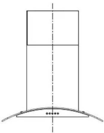
natural_image
Pure technical diagram showing a vertical structure with a curved base and dashed centerline (no text or symbols)Prav
natural_image
Simple line drawing of a curved structure with a vertical dashed line and small dots at the base (no text or symbols)Napačno
PRIKLJUČKI
RAZLIČICA SISTEMA ZA ODVOD ZRAKA Z JASKOM
natural_image
Simple line drawing of two cylindrical objects with dashed outlines, no text or symbols presentZgornji okrasni dimnik
| 1 | STIKALO ZA IZKLOP MOTORJA: Pritisnite to stikalo, da zaustavite delovanje motorja. |
| STIKALO ZA HITROST: Pritisnite na to stikalo, motor deluje z NIZKO hitrostjo. | |
| STIKALO ZA HITROST: Pritisnite na to stikalo, motor deluje pri SREDNJI hitrosti. | |
| STIKALO ZA HITROST: Pritisnite na to stikalo, motor deluje z VISOKO hitrostjo. | |
| STIKALO ZA VKLOP/IZKLOP LUČI: pritisnite na to stikalo, da vklopite luči, in ponovno pritisnite, da jih ugasnete. |
MAŠČOBNI FILTRI
ČIŠČENJE KOVINSKIH MAŠČOBNIH FILTROV
natural_image
Illustration of a hand pressing down on a tablet device (no text or symbols visible)AKTIVIRANI OGLENI FILTER (RAZLIČICA S PONOVNIM KROŽENJEM)
Odstranite priključno omarico
natural_image
Technical line drawing of a device with internal components, no visible text or symbolsOdstranite Led
natural_image
Technical line drawing of a 3D mechanical component with internal cavities and mounting brackets (no text or symbols)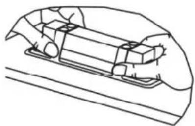
natural_image
Line drawing of a hand holding a small object inside a vehicle (no text or symbols)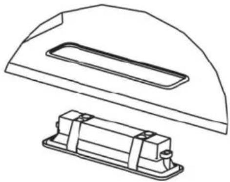
natural_image
Technical line drawing of a mechanical component with a flange and housing (no text or symbols)| Najv. moč | Napetost | Slika | Pokrov svetilke | Koda ILCOS D | |
| LED moduli z ločenim balastom | 1.5W 220V-240V | 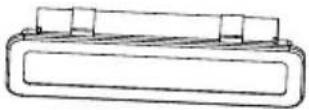 Kvadrat/premer:33.2mmx120mm Kvadrat/premer:33.2mmx120mm | / | DBS-1.5-H-33.2/120 | |
natural_image
Line drawing of a rectangular box with a curved base and mounting feet, no text or symbols presentKUHINJSKA NAPA
UPUTE ZA UPORABU
Pažljivo pročitajte ove upute prije uporabe.
natural_image
Simple line drawing of a laboratory setup with a conical flask, thermometer, and heating element (no text or symbols)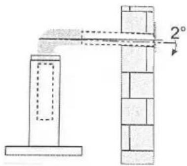
natural_image
Simple line drawing of a house with a stove and fire, no text or symbols presentnatural_image
Technical line drawing of a mechanical device with a cylindrical component and mounting base (no text or symbols)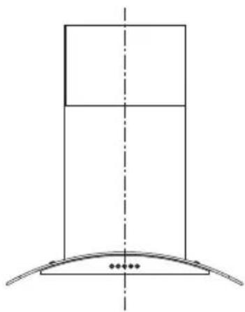
natural_image
Pure geometric diagram showing a vertical rectangle above a curved base with dots at the base (no text or symbols)Ispravno
natural_image
Simple line drawing of a curved structure with a vertical panel and dashed centerline (no text or symbols)Pogrešno
PRIKLJUČCI
NAPA SA ISPUŠNIM SUSTAVOM
Kod ugradnje kanalske izvedbe spojite napu s dimnjakom pomoću savitljive ili krute cijevi φ 150 ili φ 120 mm, izbor je prepušten instalateru.
natural_image
Two cylindrical objects with dashed outlines, one larger and one smaller, placed on a base (no text or symbols)Gornji ukrasni dimnjak
- Umetnite gornji ukrasni dimnjak 2.2 u donji ukrasni dimnjak 2.1 i povucite ga do vodoravne linije D.
- Spojite gornji ukrasni dimnjak 2.2 i nosač za pričvršćivanje dimnjaka 9 s 2 vijka 8.
UPORABA
| 1 | PREKIDAČ ZA ISKLJUČIVANJE MOTORA: Pritisnite ovaj prekidač za zaustavljanje rada motora. |
| PREKIDAČ BRZINE: Pritisnite ovaj prekidač, motor radi NISKOM brzinom. | |
| PREKIDAČ BRZINE: Pritisnite ovaj prekidač, motor radi SREDNJOM brzinom. | |
| PREKIDAČ BRZINE: Pritisnite ovaj prekidač, motor radi VELIKOM brzinom. | |
| PREKIDAČ ZA UKLJUČIVANJE/ISKLJUČIVANJE SVJETLA: Pritisnite ovaj prekidač da biste uključili svjetla, I pritisnite ga ponovo da biste ih ugasili. |
FILTERI ZA MASNOĆU
ČIŠĆENJE METALNIH SAMONOSEĆIH FILTERA ZA MASNOĆU
- Filtre je potrebno čistiti svaka 2 mjeseca rada, ili češće za posebno kod učestale uporabe, i mogu se prati u perilici posuđa.
● Povucite panele da ih otvorite. - Uklonite filtere jedan po jedan gurajući ih prema stražnjoj strani nape i istovremeno povlačeći prema dolje.
- Prilikom pranja filtara treba izbjegavati bilo kakvo savijanje. Prije ponovnog postavljanja u napu provjerite jesu li potpuno suhe. (Boja površine filtera može se mijenjati tijekom vremena, ali to nema utjecaja na učinkovitost filtera).
- Prilikom postavljanja filtara u napu pazite da su postavljeni u ispravnom položaju, s ručkom okrenutom prema van.
natural_image
Illustration of a hand pressing down on a device with a downward arrow (no text or symbols)FILTAR S AKTIVNIM UGLJENOM (VERZIJA S CIRKULIRANJEM ZRAKA)
Ovi filtri se ne mogu prati i ne mogu se regenerirati, te se moraju zamijeniti otprilike svaka 4 mjeseca rada ili češće kod veće upotrebe.
ZAMJENA FILTRA S AKTIVNIM UGLJENOM
- Uklonite metalne filtere za masnoću
- Uklonite zasićeni filtar s aktivnim ugljenom.
● Postavite nove filtere. - Vratite na mjesto metalne filtere za masnoću.
Zamjena svjetlosnih modula
natural_image
Technical line drawing of a device with internal components, no visible text or symbolsIzvadite Led
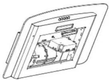
natural_image
Technical line drawing of a mechanical component with internal cavities and mounting brackets (no text or symbols)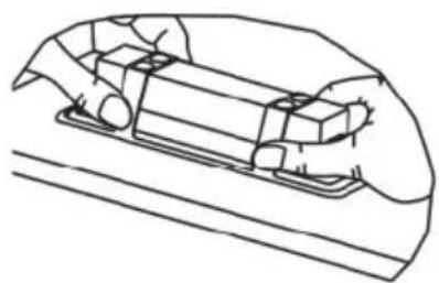
natural_image
Line drawing of a hand holding a small rectangular object, possibly a tool or component (no text or symbols present)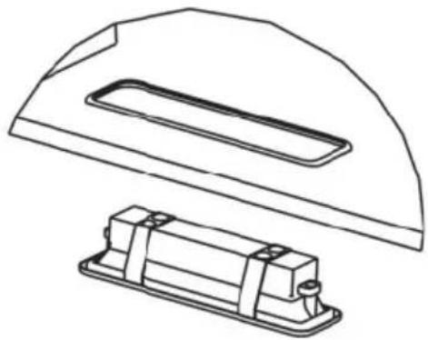
natural_image
Technical line drawing of a mechanical component with a flange and housing (no text or symbols)| Maks. snaga | Napon | Slika | Pokopac svjetla | ILCOS D kod | |
| LED moduli s vlastitim balastom | 1.5W | 220V-240V | 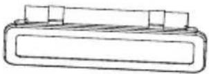 Kvadrat/promjer:33,2mmx120mm Kvadrat/promjer:33,2mmx120mm | / | DBS-1.5-H-33.2/120 |
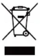
Europska Direktiva 2012/19/EU o otpadnoj električnoj i elektroničkoj opremi (WEEE) zahtijeva da se stari električni kućanski uređaji ne smiju odlagati u uobičajeni nerazvrstani gradski otpad. Stari uređaji moraju se prikupljati odvojeno kako bi se optimizirala oporaba i recikliranje materijala koje sadrže i smanjio utjecaj na ljudsko zdravlje i okoliš. Simbol prekrižene "kante za otpad" na proizvodu podsjeća vas na vašu obvezu da kada želite zbrinuti uređaj, mora se skupljati odvojeno. Potrošači bi se trebali obratiti svojim lokalnim vlastima ili trgovcu za informacije o pravilnom odlaganju svojih starih uređaja.
natural_image
Line drawing of a rectangular box mounted on a curved base, with no visible text or symbols.АСПИРАТОР
natural_image
Simple line drawing of a laboratory setup with a conical flask, thermometer, and heating element (no text or symbols)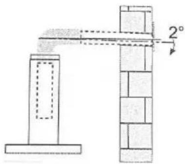
natural_image
Simple line drawing of a house with a stove and fire, no text or symbols present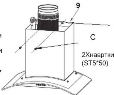
natural_image
Technical line drawing of a mechanical device with a cylindrical component and mounting base (no text or symbols)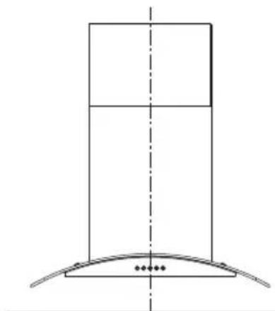
natural_image
Pure technical diagram showing a vertical structure with a curved base and dotted markers at the base (no text or symbols)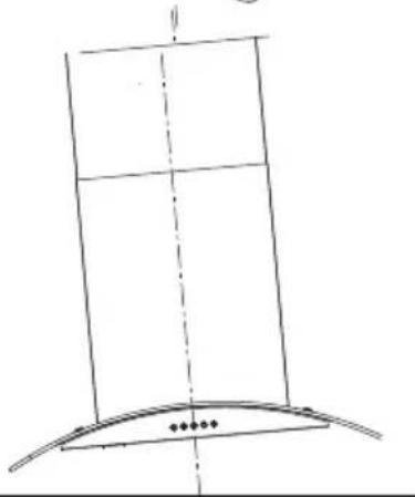
natural_image
Simple line drawing of a vertical structure with a curved base and dashed vertical line, no text or symbols present.Точно
Погрешно
ПОВРЗУВАЊЕ
natural_image
Illustration of a hand interacting with a smartphone screen, showing a finger pointing at the screen (no text or symbols present)ФИЛТЕР СО АКТИВНИОТ ЈАГЛЕН (ВЕРЗИЈА СО КРУЖЕЊЕ)
natural_image
Technical line drawing of a device with internal components and mounting bracket (no text or symbols)Извадете го Лед
natural_image
Technical line drawing of a mechanical component with internal cavities and mounting brackets (no text or symbols)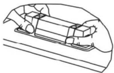
natural_image
Line drawing of a hand holding a small object inside a vehicle (no text or symbols)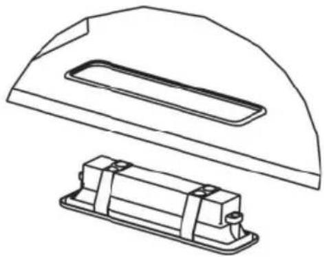
natural_image
Technical line drawing of a mechanical component with a flange and housing (no text or symbols)natural_image
Line drawing of a rectangular box mounted on a curved base, with no visible text or symbols.EXAUSTOR DE COZINHA
MANUAL DE INSTRUÇÕES
natural_image
Simple line drawing of a laboratory setup with a conical flask, heated by a Bunsen burner and a control panel (no text or symbols)UTILIZAÇÃO
natural_image
Simple line drawing of a house with a pot and steam rising, no text or symbols present
natural_image
Technical line drawing of a mechanical device with a cylindrical component and mounting base (no text or symbols)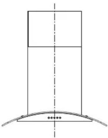
natural_image
Pure technical diagram of a vertical structure with a curved base and dashed centerline (no text or symbols)Certo
natural_image
Simple line drawing of a vertical structure with a curved base and dashed vertical line, no text or symbols present.Errado
CONEXÕES
SISTEMA DE EXAUSTÃO DE AR DA VERSÃO COM CONDUTAS
natural_image
Simple line drawing of two cylindrical objects with dashed outlines, no text or symbols presentChaminé decorativa superior
natural_image
Illustration of a hand interacting with a tablet device (no text or symbols visible)natural_image
Technical line drawing of a device with internal components and mounting bracket (no text or symbols)Retire o Led
natural_image
Technical line drawing of a 3D mechanical component with internal components (no text or symbols)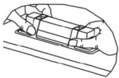
natural_image
Line drawing of a hand holding a rectangular object with mounting holes, partially enclosed in a curved frame (no text or symbols)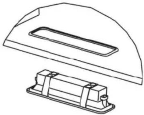
natural_image
Technical line drawing of a mechanical component with a flange and housing (no text or symbols)natural_image
Line drawing of a rectangular box with a curved base and mounting feet, no text or symbols presentАСПИРАТОР
РЪКОВОДСТВО ЗА УПОТРЕБА
natural_image
Simple line drawing of a laboratory setup with a conical flask, test tube, and heating lamp (no text or symbols)УПОТРЕБА
natural_image
Simple line drawing of a house with a chimney and a burning plant, no text or symbols present
natural_image
Technical line drawing of a mechanical device with a cylindrical component and mounting base (no text or symbols)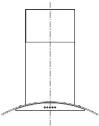
natural_image
Pure technical diagram showing a vertical structure with a curved base and dashed centerline (no text or symbols)Правилно
natural_image
Simple line drawing of a curved structure with a vertical panel and small dots at the base (no text or symbols)Неправилно
ВРЪЗКИ
natural_image
Simple line drawing of two cylindrical objects with dashed outlines, no text or symbols presentnatural_image
Illustration of a hand interacting with a tablet device, showing a finger pointing at the screen (no text or symbols present)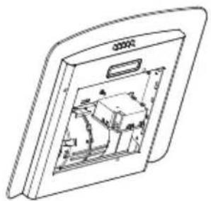
natural_image
Technical line drawing of a device with internal components, no visible text or symbols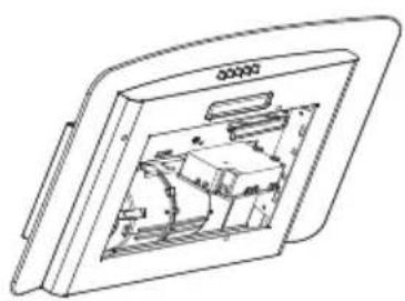
natural_image
Technical line drawing of a 3D mechanical component with internal cavities and mounting brackets (no text or symbols)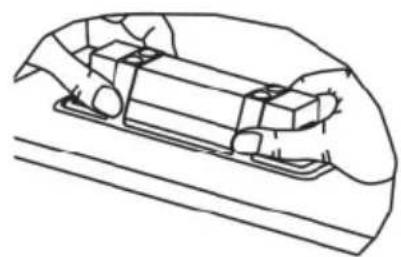
natural_image
Line drawing of a hand using a tool to adjust or install a component on a surface (no text or symbols)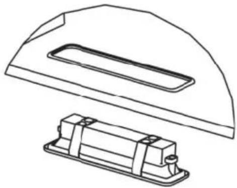
natural_image
Technical line drawing of a mechanical component with a flange and housing (no text or symbols)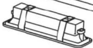
natural_image
Technical line drawing of a rectangular mechanical component with mounting holes (no text or symbols)natural_image
Line drawing of a rectangular box with a curved base and mounting feet, no text or symbols presentΑΠΟΡΡΟΦΗΤΗΡΑΣ
ΕΓΧΕΙΡΙΔΙΟ ΧΡΗΣΗΣ
natural_image
Simple line drawing of a heating setup with a lamp, condenser, and control panel (no text or symbols)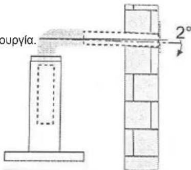
natural_image
Simple line drawing of a house with a pot and fire, no text or symbols present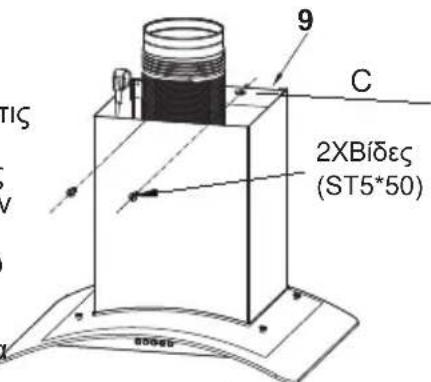
natural_image
Technical line drawing of a mechanical device with a cylindrical component and mounting base (no text or symbols)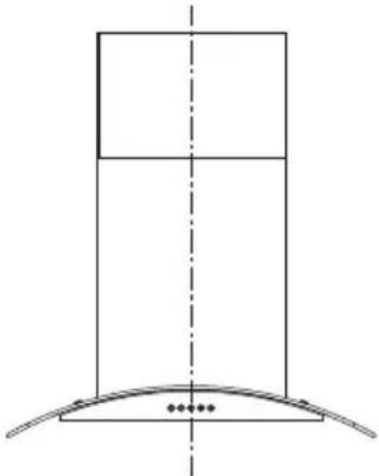
natural_image
Pure technical diagram of a vertical structure with a curved base and dashed centerline, no text or symbols present.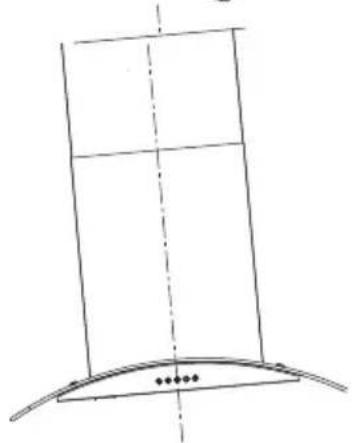
natural_image
Simple line drawing of a curved structure with a vertical panel and dashed centerline (no text or symbols)Σωστό
Λάθος
ΣΥΝΔΕΣΕΙΣ
natural_image
Simple line drawing of two cylindrical objects with dashed outlines, no text or symbols presentnatural_image
Illustration of a hand pressing down on a tablet device with a downward arrow (no text or symbols)natural_image
Technical line drawing of a mechanical component with internal structure (no text or symbols)Βγάλτε το Led
natural_image
Technical line drawing of a mechanical component with internal cavities and mounting brackets (no text or symbols)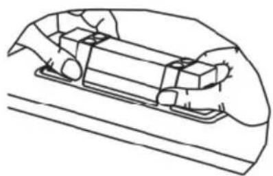
natural_image
Line drawing of a hand holding a small object inside a vehicle (no text or symbols)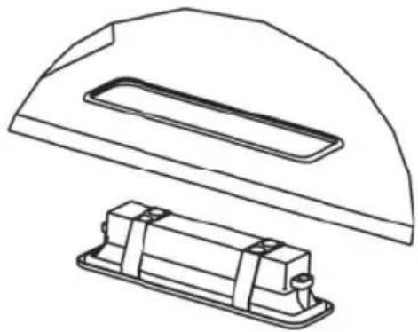
natural_image
Technical line drawing of a mechanical component with a flange and housing (no text or symbols)natural_image
Line drawing of a rectangular box mounted on a curved base, with no visible text or symbols.CAMPANA EXTRACTORA
natural_image
Illustration of a laboratory setup with a conical flask, thermometer, and gas stove (no text or symbols)USO
natural_image
Simple line drawing of a house with a stove and fire, no text or symbols presentnatural_image
Technical line drawing of a mechanical device with a cylindrical component and mounting base (no text or symbols)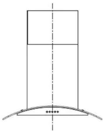
natural_image
Pure geometric diagram showing a vertical rectangle above a curved base with dots at the base (no text or symbols)Correcto
natural_image
Simple line drawing of a curved structure with a vertical panel and dashed centerline (no text or symbols)Incorrecto
CONEXIONES
natural_image
Simple line drawing of two cylindrical objects with dashed outlines, no text or symbols presentChimenea Decorativa Superior
natural_image
Illustration of a hand pressing down on a tablet device with a downward arrow (no text or symbols)natural_image
Technical line drawing of a mechanical assembly inside a rectangular frame (no text or symbols)Saque la luz Led
natural_image
Technical line drawing of a mechanical component or enclosure with internal compartments and mounting brackets (no text or symbols)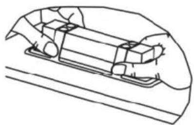
natural_image
Line drawing of a hand holding a small object inside a vehicle (no text or symbols)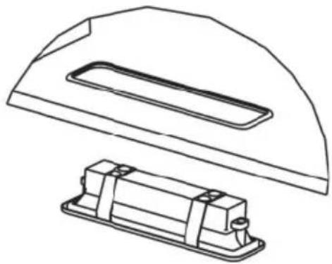
natural_image
Technical line drawing of a mechanical component with a flange and housing (no text or symbols)- COOKER HOOD
- INSTRUCTION MANUAL
- INSTALLATION
- USE
- MAINTENANCE
- WALL DRILLING AND BRACKET FIXING
- As a first step, proceed with the following drawings:
- Mark Points:
- Fix the brackets:
- Fix lower decorative chimney
- Hook the hood body
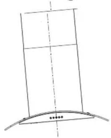
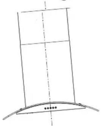
- Right Wrong
- CONNECTIONS
- DUCTED VERSION AIR EXHAUST SYSTEM
- Upper Decorative Chimney
- GREASE FILTERS
- ACTIVATED CHARCOAL FILTER (RECIRCULATION VERSION)
- REPLACING THE ACTIVATED CHARCOAL FILTER
- Replacing the light modules
- ASPIRATOR
- UPUTSTVO ZA UPOTREBU
- UPOTREBA
- ODRŽAVANJE
- BUŠENJE ZIDA I MONTAŽA NOSAČA
- Ispravno
- Pogrešno
- POVEZIVANJE
- ASPIRATOR SA IZDUVNIM SISTEMOM
- Gornji dekorativni dimnjak
- FILTERI ZA MASNOĆU
- ČIŠĆENJE METALNIH SAMONOSEĆIH FILTERA ZA MASNOĆU
- AKTIVNI UGLJENI FILTER (VERZIJA SA RECIRKULACIJOM)
- Zamena svetlosnih modula
- NAVODILA ZA UPORABO
- PRIKLJUČKI
- RAZLIČICA SISTEMA ZA ODVOD ZRAKA Z JASKOM
- Zgornji okrasni dimnik
- MAŠČOBNI FILTRI
- ČIŠČENJE KOVINSKIH MAŠČOBNIH FILTROV
- AKTIVIRANI OGLENI FILTER (RAZLIČICA S PONOVNIM KROŽENJEM)
- KUHINJSKA NAPA
- UPUTE ZA UPORABU
- PRIKLJUČCI
- NAPA SA ISPUŠNIM SUSTAVOM
- Gornji ukrasni dimnjak
- UPORABA
- FILTAR S AKTIVNIM UGLJENOM (VERZIJA S CIRKULIRANJEM ZRAKA)
- ZAMJENA FILTRA S AKTIVNIM UGLJENOM
- Zamjena svjetlosnih modula
- ПОВРЗУВАЊЕ
- ФИЛТЕР СО АКТИВНИОТ ЈАГЛЕН (ВЕРЗИЈА СО КРУЖЕЊЕ)
- EXAUSTOR DE COZINHA
- MANUAL DE INSTRUÇÕES
- UTILIZAÇÃO
- CONEXÕES
- SISTEMA DE EXAUSTÃO DE AR DA VERSÃO COM CONDUTAS
- Chaminé decorativa superior
- РЪКОВОДСТВО ЗА УПОТРЕБА
- УПОТРЕБА
- ВРЪЗКИ
- ΕΓΧΕΙΡΙΔΙΟ ΧΡΗΣΗΣ
- Σωστό
- Λάθος
- ΣΥΝΔΕΣΕΙΣ
- CAMPANA EXTRACTORA
- USO
- CONEXIONES
- Chimenea Decorativa Superior
Brand : VOX
Model : CGL6V17IX
Category : Range hood