
CGL 950 IX - Range hood VOX - Free user manual and instructions
Find the device manual for free CGL 950 IX VOX in PDF.


| Product Type | Cooker Hood (Range Hood) |
| Brand | VOX |
| Model | CGL 950 IX |
| Power Supply | 220-240 V ~ 50 Hz |
| Appliance Insulation Class | Class I |
| Motor Insulation Class | F |
| Speed Levels | 3 speeds + Timer (15 minutes) |
| Control Type | Touch button on glass (3 spd) and push button |
| Lighting | Halogen lamp or Spark plug lamp (replaceable) |
| Grease Filter Material | Aluminum |
| Carbon Filter (Optional) | Yes, for recirculation mode |
| Carbon Filter Replacement Interval | Every 3–5 months |
| Grease Filter Cleaning Interval | Every 2–3 weeks or when "C" appears on display |
| Grease Filter Dishwasher Safe | Yes |
| Exhaust Air Mode | Yes (external ducting required) |
| Recirculation Mode | Yes (with carbon filter) |
| Minimum Distance – Electric Hob | 650 mm |
| Minimum Distance – Gas Hob | 750 mm |
| Air Outlet Diameter | 150 mm (recommended), min 120 mm |
| Maximum Product Weight | 40 kg |
| Power Cord Length | Approx. 1.3 m |
| Fuse Rating | MAX 6 A |
| Package Contents | Product, inner/outer flue, plastic flue, flue connection plate, screws, dowels, user manual |
Frequently Asked Questions - CGL 950 IX VOX
User questions about CGL 950 IX VOX
0 question about this device. Answer the ones you know or ask your own.
Ask a new question about this device
Download the instructions for your Range hood in PDF format for free! Find your manual CGL 950 IX - VOX and take your electronic device back in hand. On this page are published all the documents necessary for the use of your device. CGL 950 IX by VOX.
USER MANUAL CGL 950 IX VOX
GBR
SRB
CGL650IX / CGL950IX
OPERATING INSTRUCTIONS COOKER HOOD UPUTSTVO ZA UPOTREBU ASPIRATOR NAVODILA ZA UPORABO KUHINJSKA NAPA UPUTE ZA UPORABU KUHINJSKA NAPA MANUAL DE ISTRUÇÕES EXAUSTOR

CGL650IX / CGL950IX
OPERATING INSTRUCTIONS COOKER HOOD
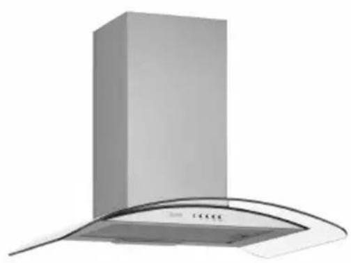
MODEL: CGL650IX
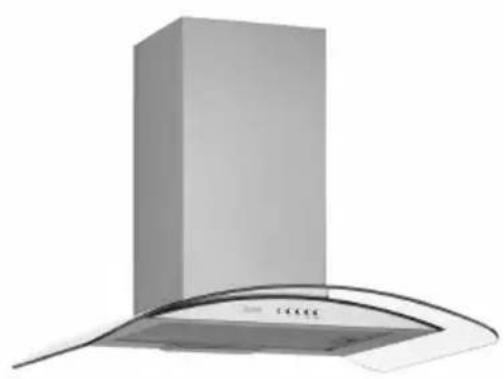
natural_image
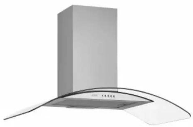
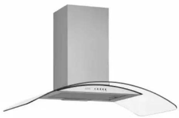
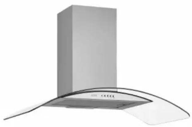
Exterior view of a modern stainless steel kitchen chimney with curved roof (no text or symbols visible)MODEL: CGL950IX
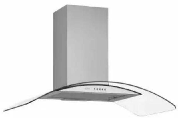
natural_image
Exterior view of a modern kitchen air conditioner unit with a cylindrical top and curved cover (no text or symbols visible)Read the User Manual Carefully!
1 TECHNICAL DRAWING 4
2 WARNINGS AND SAFETY PRECAUTIONS 5
2.1 Life-Threatening Danger, Poisoning Danger 7
2.2 Danger of electric shock! 7
2.3 Danger of physical injury! 7
2.4 Danger of burn, danger of electric shock! 8
2.5 Dangers of fire and physical injury! 8
3 USAGES WITH AND WITHOUT CARBON FILTER 9
3.1 Replacement of Carbon Filter 10
3.2 Replacement of Carbon Filter 10
4 CLEANING AND PREVENTIVE MAINTENANCE 11
4.1 Washing in Dishwasher 11
4.2 Hand Wash 11
4.3 Removal/Installation of Aluminium Filter 11
5 INSTALLATION OF APPLIANCE 12
5.1 Installation and Unpacking of the Appliance 12
5.2 Installation and Unpacking of the Appliance 12
5.3 Exhaust Air Mode 13
5.4 Air Discharge Line 13
5.5 Checking the Wall 13
5.6 Electrical Connection 13
5.7 Danger of Electric Shock! 13
6 CONTENT OF PACKAGE 14
7 OVERVIEW OF COOKER HOOD 15
8 ASSEMBLY OF PRODUCT 16
8.1 Installation Diagram and Components 16
8.2 Assembly of Plastic Flue 17
9 ASSEMBLY OF PLATE FUELS 18
10 USE OF PRODUCT 19
10.1 On Glass 3 Spd Touch Button 19
10.2 Push Button 19
11 REPLACEMENT OF LAMPS 20
11.1 Replacement of Halogen Lamp 20
11.2 Replacement of Spark Plug Lamp 20
12 AUTHORIZED TECHNICAL SERVICE 21
12.1 Potential Failures and Solutions 22
12.2 Technical Table 22
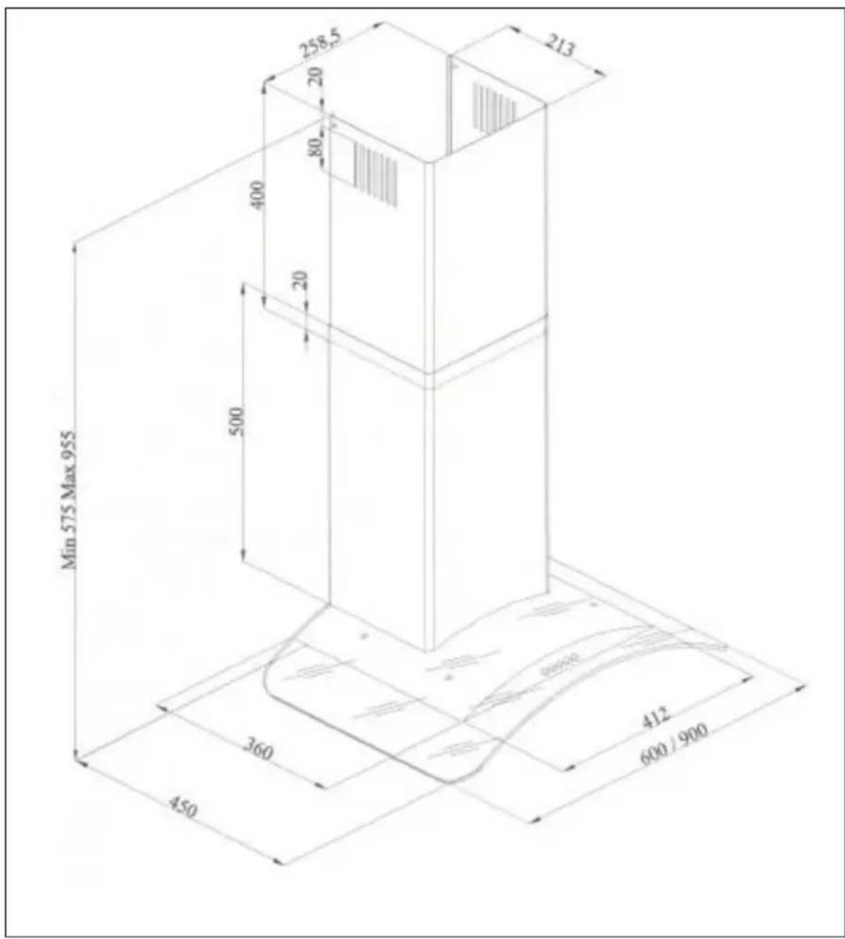
1 TECHNICAL DRAWING
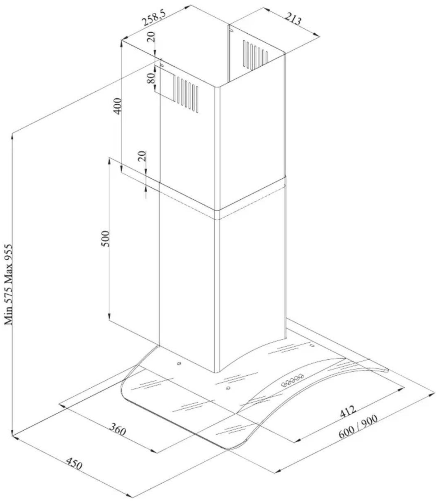
Fig. 1: TECHNICAL DRAWING
2 WARNINGS AND SAFETY PRECAUTIONS
■ This appliance can be used by children aged from 8 years and above and persons with reduced physical, sensory or mental capabilities or lack of experience and knowledge if they have been given supervision or instruction concerning use of the appliance in a safe way and understand the hazards involved.
■ This product is designed for home use.
■ Usage voltage of your product is 220-240 Volt\~50 Hz.
■ Power cord of your product is fitted with a grounded plug. That cable must definitely be connected to a grounded socket.
■ The whole electrical wiring must be installed by a qualified electrician.
■ Installation by unauthorized persons could lead to poor operation performance, damage to the product, and accidents.
- Feeder cable of the appliance mustn't be exposed to jamming or crashing during assembly. Feeder cable mustn't be placed near the cooker. In such cases, it might melt down and lead to fire.
■ Do not plug in the appliance before the installation.
■ Make sure that the installation place allows the user to easily unplug the power cable in case of any danger.
■ Do not touch your product's lamps when they work for a long time. Since they would be hot, they could burn your hand.
■ Kitchen cooker hoods are designed for normal cooking and home use. For uses other than specified, there is the risk of failure and the appliance becomes out of warranty.
■ Comply with the rules and instructions regarding discharge of outgoing air, stipulated by the relevant authorities. (This warning does not
apply to uses without flue.)
■ Flammable foods must not be cooked under the appliance.
■ Turn on the appliance after placing a saucepan, pan, etc. on the cooker. Otherwise, high temperature might lead to deformation on some components of your product.
■ Turn off the cooker's burner before taking the saucepan, pan, etc. off the cooker.
■ Do not leave hot oil on your cooker. Pots that contain hot oil might lead to inflammation.
■ Since oils could catch fire when you cook fried foods in particular, be careful about your curtains and tablecloths.
■ Ensure timely replacement of the filters. Filters not replaced in a timely manner pose risk of fire due to accumulated grease deposits on them.
■ Do not use non-fire-resistant filtering materials instead of the filter.
■ Do not operate your product without filter, and do not remove the filters when the product is in use.
■ In case of any deflagration, de-energize the cooker hood and cooking appliances. (Plug off the appliance or turn off the main switch).
If your product's periodic cleaning is not made in a timely manner, it could pose risk of fire.
■ De-energize the appliance before any maintenance operations. (Plug off the appliance or turn off the main switch.)
■ When electric cooker hood and devices fed with energies other than electricity operate simultaneously, the negative pressure in the room must not exceed 4 Pa (4 X 10 bar).
■ Gas or fuel oil burning appliances, such as room heaters, which share the same environ-
ment with your product, must be fully insulated from the exhaust of this product or they must be hermetical.
■ When you make a flue connection for your product, use pipes with a diameter of 150mm or 120 mm.
■ The length of the pipe connection as well as the number of elbows must be as minimum as possible.
■ Children should not tamper with the device.
■ For your safety, use "MAX 6 A" fuse in the cooker hood system.
■ Since the packing materials could be dangerous, keep them away from children.
■ If the feeder cable is damaged, it must be replaced by its manufacturer or authorized technical service or any other personnel qualified at the same level, in order to avoid any dangerous situation.
■ In case of any deflagration, de-energize the cooker hood and cooking appliances, and cover the flame. Never use water to extinguish the fire.
■ When cooking appliances are in operation, their accessible parts could be hot.
■ This appliance is not intended to be used by people with physical, sensory and mental disabilities (including children) or those who have not adequate experience and knowledge regarding its use, unless they are under the supervision of a person responsible for the safety of the appliance.
■ After the installation of the cooker hood, the minimum distance must be 65 cm between the product and any electric cooker; and 75 cm between it and any gas ranges or cookers burning other fuels.
■ Output of the cooker hood must not be connected to air ducts, where there exist another smokes.
■ You must be careful when using the appliance spontaneously with other appliances (e.g. gas, diesel fuels, coal or wood burning heaters, shower heaters, etc.) which use the same air in the same environment. It is because the cooker hood could adversely affect the combustion, by discharging the ambient air.
■ This warning does not apply to uses without flue.
■ When electric cooker hood is used simultaneously with devices that use gas or other fuels, there must be sufficient ventilation in the room (might not apply to devices that discharges the air back into the room).
■ Simultaneous operation of more than one gas cooker leads to generation of high heat. A ventilation appliance placed on the surface of cookers might therefore get damaged or burn. Do not operate two gas cookers in high heat for more than 15 minutes. One large burner with more than 5kW (Work) power generates power equal to that of two gas burners.
2.1 Life-Threatening Danger, Poisoning Danger

DANGER
There are life-threatening danger and poisoning danger due to reabsorbed combustion gases. During the air discharge outlet use, unless sufficient air supply is provided, do not use the appliance simultaneously with devices that discharge toxic gases through flue such as ventilated, gas, oil, wood or coal burning heaters, shower heaters, water heaters, etc.
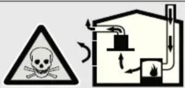
Fig. 2: Poisoning Danger
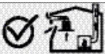
Ventilated devices (e.g. gas, oil, wood or coal burning heaters, shower heaters, water heaters) take combustion air from the installation location, and discharge the waste gas through a waste gas system (e.g. flue). When the cooker hood is active, it absorbs air from the kitchen and neighbouring rooms. If adequate air entry is not provided vacuum emerges. In such a case, the toxic gases are absorbed from the flue and waste gas channel, and are taken into to door again. Fig. 2 Therefore, adequate fresh air ingress must always be ensured. Fig. 3
natural_image
Simple line drawing of a house with a checkmark and a downward arrow (no text or symbols)Fig. 3

DANGER
Fire danger!
Due to sparkling. Installation of appliance over a heating device that is heated by using solid fuels (for ex. wood or coal) is only allowed if an non-detachable cover is present. For the installation process, attention must be paid to current applicable construction regulations and regulations of local electric and gas companies.
Appliance might lead to fire unless it is produced in accordance with cleaning instructions.

DANGER
2.2 Danger of electric shock!
Do not bend or jam the connection cable during installation due to danger of damaged connection cable.

DANGER
2.3 Danger of physical injury!
■ During the installation, there is a danger of physical injury due to the sharp edges. Use protective gloves throughout the installation process of the appliance.
■ Due to risk of dropping the appliance, assembly of all safety bolts and covers must be performed as specified in the user manual.

DANGER
2.4 Danger of burn, danger of electric shock!
■ Allow the appliance to cool before cleaning or maintenance process. Switch off the fuse or pull out the mains plug from the socket.
■ There is risk of damage due to ingress of moisture in the electronics. Do not clean the control components with a wet cloth.
■ The surface could be damaged due to a wrong cleaning process. Clean stainless steel surfaces only in their brushing direction. Do not use a stainless steel cleaner for the control elements.
■ The surface could be damaged due to aggressive and abrasive cleaning agents. Never use use aggressive and abrasive cleaning agents.
■ There is risk of damage due to backflow of condensate. Mount the air outlet channel downwards from the appliance (slope of 1^ ).

DANGER
2.5 Dangers of fire and physical injury!
In case of repairing that is not performed according to the rules or as required, turn off the fuse or unplug the feeder cable of your appliance. Repairing must be performed only by the authorized technical service or authorized experts.
NOTE
If the appliance is faulty or damages, turn off the fuse or unplug the feeder cable of your appliance and call the authorized service.
NOTE
If the feeder cable is damaged, it must be replaced by its manufacturer or its authorized technical service or any other personnel qualified at the same level, in order to avoid any dangerous situation.
NOTE
If the bulbs of your appliance are faulty, turn off the fuse or unplug the feeder cable of your appliance. Replace the bulbs immediately to avoid overload on other bulbs (wait for the bulbs to cool down first)

DANGER
Accessible components might be heated when used with cooking devices.

DANGER
Air outlet pipe of this appliance mustn't be connected in the flue used to discharge the fume generated by devices that use gas or other fuels.
3 USAGES WITH AND WITHOUT CARBON FILTER
You can use this appliance in exhaust air mode and ventilated air mode.
Exhaust air mode
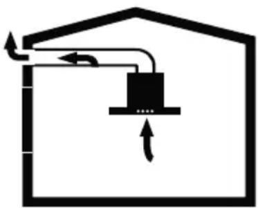
The absorbed air is cleaned by the grease filters, and is discharged through a piping system. Fig.4
natural_image
Simple line diagram of a house with a central box and directional arrows, no text or symbols present.Fig. 4: Air Outlet without Carbon Filter

WARNING
Death Risk!

Exhaust gases that are reabsorbed might lead to poisoning. Exhaust air must not be transferred to an active smoke or waste gas flue; or a flue used for ventilation of the places, where heat sources are installed.
■ If you want to transfer exhaust air to an inactive smoke or waste gas flue, you need to obtain permission from an authorized chimney sweep.
■ If exhaust air is discharged through the external wall, a telescopic wall safe must be used.
Ventilated air mode

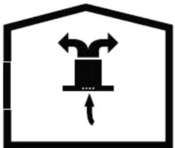
Absorbed air is cleaned by the grease filters and an active carbon filter, and then it is transferred back to the kitchen. Fig.5
natural_image
Symbolic icon of a box inside a house outline, with arrows indicating direction (no text or labels)Fig. 5: Air Outlet with Carbon Filter
To retain the substances that lead to odour in ventilated air mode, you must attach an active carbon filter. Consult your authorized dealer for various options available to use your appliance in ventilated air mode. You can purchase the accessories required for this process for related sales points, authorized services or online sales centre
3.1 Replacement of Carbon Filter
In environments without flue, active carbon filter must be used for filtering the air and resending it in. Active carbon filter must be supplied from service or your dealer. De-energize the appliance before replacing the carbon filter. Since carbon filter is used in kitchens with no flue outlet, it must be replaced in every 3-5 months depending on the use.
Carbon filter must never be washed. Grease filters must be installed in the product, regardless of whether or not carbon filters are used. Do not use your product without grease filter.
3.2 Replacement of Carbon Filter
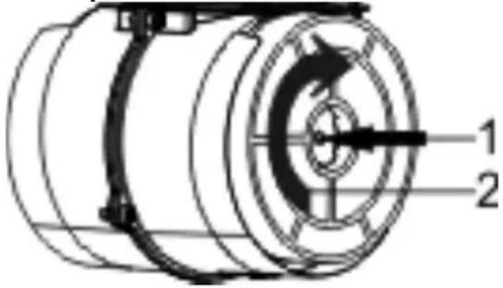
Fig. 6: CARBON FILTER
The appliance you have purchased is appropriate for use with carbon filters.
- Place the carbon filter in its housing. Fig. 6
- Rotating the carbon filter clockwise, ensure that it is completely fit. Fig. 6

If carbon filter does not fit in completely, it might drop and damage your product.
DANGER
Do not wash carbon filters. Keep the carbon filters away from children.
4 CLEANING AND PREVENTI- VE MAINTENANCE

DANGER
■ Prior to each maintenance and cleaning, cooker hood must be unplugged, and appliance must be dead
■ Cleaning and user maintenance of the appliance shall not be performed by unattended children.
■ The surface could be damaged due to aggressive and abrasive cleaning agents. Never use aggressive and abrasive cleaning agents. Supply your cleaning and protective substances that are appropriate for your appliance from the authorized technical service. Surface of appliance and control units are sensitive to scratching.
■ Clean the surfaces with a soft and damp cloth, dish-washing liquid or mild glass cleaning agent. Soften the dry, sticky dirt with a damp cloth. Do not scrape!
■ It is not appropriate to use dry cloths, sponges that may scratch, materials that require rubbing, and other aggressive cleaning agents containing sand, soda, acid or chlorine.
■ Clean the stainless steel surfaces in their brushing direction only.
■ Do not use stainless steel cleaning agents and wet clothes for control units. Cleaning of metal grease filters Used metal grease filters retain the greasy particles in the moisture and vapour generated in the kitchen. Clean the metal grease filters about every three months, under normal use conditions (1 to 2 hours a day).
■ Do not use excessively effective, acidic or alkaline cleaning agents.
■ For cleaning the metal grease filters, clean the holder parts of the metal grease filters in the appliance, with a damp cloth as well.
■ You can clean the metal grease filters in the dishwasher or by hand.
4.1 Washing in Dishwasher
■ In case of washing in dishwasher, a slight change might occur in colour. This has no effect on the function of the metal grease filter.
■ Do not wash the excessively dirty metal grease filters together with dishes.
■ Place the metal grease filters loosely and freely in the dishwasher. Metal grease filters must be placed in the dishwasher without jamming.
4.2 Hand Wash
For stubborn dirt, you can use a special grease solvent. You can buy such an agent from the authorized sales centre.
■ Soften the metal grease filters in a hot water with dish-washing liquid.
■ Use a brush for cleaning and wait for the liquid in metal grease filters to flow off completely.
■ Rinse the filters thoroughly after cleaning.

DANGER
Thanks to timely cleaning of metal grease filter, the fire danger caused by excessive heat that is generated during frying is avoided.
4.3 Removal/Installation of Aluminium Filter
Pull the aluminium filter towards you by pressing on its tab. Reverse the process to install the filter.
5 INSTALLATION OF APPLIANCE
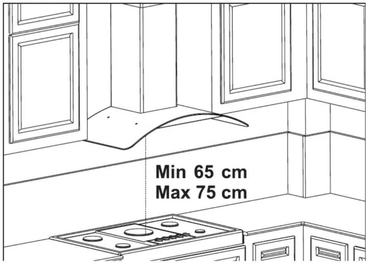
Fig. 7: INSTALLATION OF APPLIANCE
After completing the installation of cooker hood, the minimum distance must be 650 mm between the product and any electric cooker; and 750 mm between it and any gas ranges or cookers burning other fuels. Fig. 7
5.1 Installation and Unpacking of the Appliance
Check that your appliance is not deformed.
■ Report the transport issues immediately transport operator.
■ Any faults encountered shall be reported the dealer, too.
■ Do not allow children to play the with packaging materials !!!
5.2 Recommendation for Energy Saving
■ Replace the carbon filters on a regular basis.
Regularly clean your aluminium filters. Since dirty filters would block the air passage, you might have to use the appliance at a higher speed.
■ Use your product according to its normal speeds.
■ Use at higher speed would cause an increase in the energy consumption.
5.3 Exhaust Air Mode

WARNING
Death Risk!
Exhaust gases that are reabsorbed might lead to poisoning. Exhaust air must not be transferred to an active smoke or waste gas flue; or a flue used for ventilation of the places, where heat sources are installed. If you want to transfer exhaust air to an inactive smoke or waste gas flue, you need to obtain permission from an authorized chimney sweep.
If exhaust air is discharged over the external wall, a telescopic wall case must be used..
5.4 Air Discharge Line
Information: Manufacturer of appliance cannot be held responsible for defects caused by laid pipes.
■ Appliance shows the highest performance when a short and flat air outlet pipe and a pipe diameter as large as possible is used.
■ Optimum ventilation performance cannot be reached and noise of fan increases when long and rough air outlet pipes and multiple pipe elbows or pipe diameters smaller than 150mm are used.
■ Pipes or hoses used in laying the air outlet line must be made of inflammable materials.
Circular Pipes
It is recommended that inner diameter should be 150 mm or at least 120 mm.
Flat Channels
Inner Section must be appropriate to the diameter of circular pipes.
∅150 mm approx. 177 cm²
∅150 mm approx. 173 cm²
■ Flat channels shouldn't have sharp elbows.
■ Use sealing strips for different pipe diameters.
5.5 Checking the Wall
■ Wall must be flat, straight and have the sufficient bearing capacity.
■ Depth of drilling holes must comply with the length of bolts. Dowels must fit in properly.
■ Bolts and dowels in the enclosure are appropriate for use in rigid monolithic walls. Use appropriate fasting materials for different constructions (for ex. plasterboard, aerated concrete, proton bricks).
■ Maximum weight of your cooker hood is 40 Kg.
5.6 Electrical Connection

WARNING
Electric Shock Danger!
Components in the appliance might have sharp edges. Connection cable can be damaged. Do not bend or jam the connection cable during installation.
Necessary connection data is provided on the type label found inside your appliance; metal grease filters must be removed to see the label.
Length of connection line: approx. 1.3 m
This appliance complies with EU interference elimination guidelines.

WARNING
5.7 Danger of Electric Shock!
It must always be possible to disconnect the appliance from the electric network. Appliance must be plugged in a protected contact outlet that is mounted in accordance with the rules. If the plug cannot be reached after installation or during the required fixed connection, there must be many pole separation assemblies available with at least 3 mm contact distance to the installation. Fixed connection must be performed by an electronics expert only.
6 CONTENT OF PACKAGE
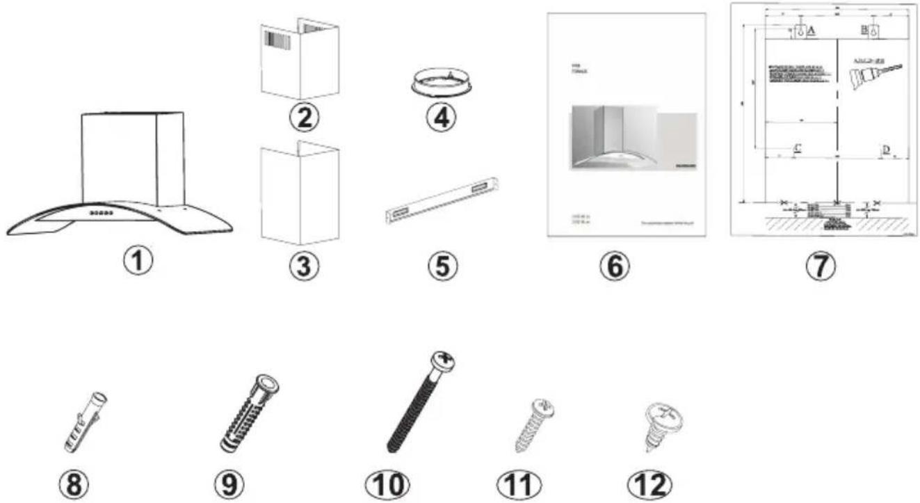
Fig. 8: CONTENT OF PACKAGE
- Product
- Inner Flue
- Outer Flue
- 120mm Plastic Flue
- Flue Connection Plate
- User Manual
- Assembly Pattern
- 2x ∅6mm Plastic Dowel
- x ∅10mm Plastic Dowel
- 3x 5.5x60 Wall Mount Screw
- 2x 3.9x22 Flue Connection Plate Screw
- 3.5x9.5 Flue Connection Screw
7 OVERVIEW OF COOKER HOOD

Fig. 9: OVERVIEW OF COOKER HOOD
- Inner Flue
- Outer Flue
- Glass
- Cooker Lighting
- Control Panel Layout
- Filter
8 ASSEMBLY OF PRODUCT
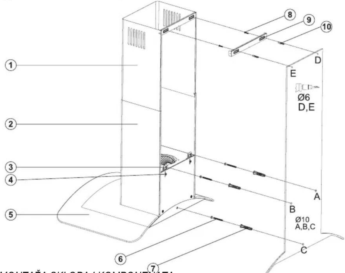
8.1 Installation Diagram and Components
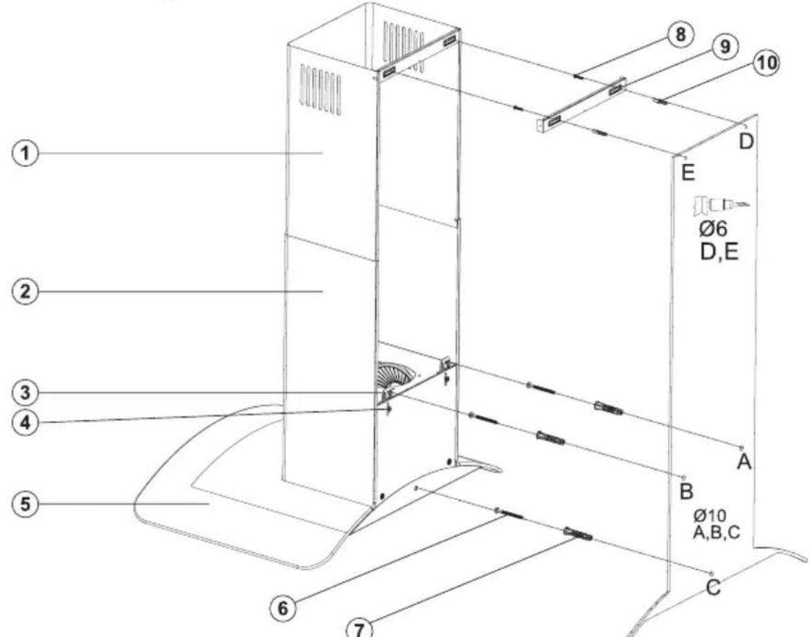
Fig. 10: ASSEMBLY INSTALLATION AND COMPONENTS
- Inner Flue
- Outer Flue
- Product Hanging Plate
- Product Hanging Plate Fixing Screw
- Glass
- 3x 5.5x60 Wall Mount Screw
- 3x ∅10mm Plastic Dowel
- 2 × 3.9 × 22 Screw
- Flue Connection Plate
- 2x ∅6mm Plastic Dowel
specified height (See the minimum and maximum distances intended for the worktop, in the assembly pattern). Perforate points A, B and C.(Fig. 10)
■ Insert ∅10mm dowels (7) into the holes drilled as A, B, C and D, and screw down the screws at the points A + B so that 5mm space remains between the screw head and the wall. (Fig. 10)
■ Hang it on the wall with the hanging plate of the cooker hood.
■ Tighten A + B fixing screws on the wall, and
■ Loosening the product hanging plate fixing completely secure the product at point C.
screw (4) pull the hanging plates (3) upwards, and fix the hanging plated by re-tightening the fixing screw. Fig 10
■ Assemble the cooker hood with the help of the assembly scheme. (Fig. 8 / 7)
■ Affix the assembly pattern on the wall, at the
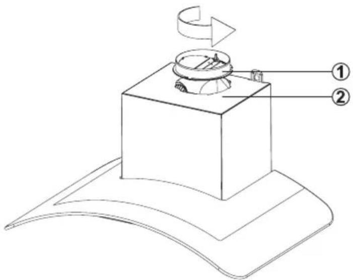
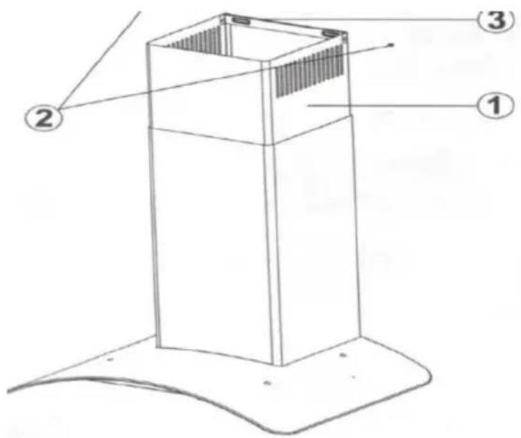
8.2 Assembly of Plastic Flue
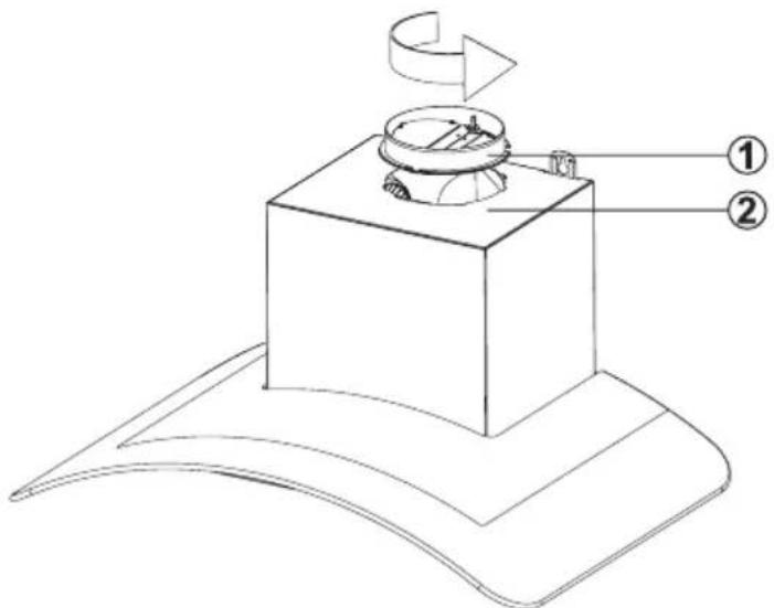
Fig. 11: PLASTIC FLUE CONNECTION
- 120 mm Flue Adapter
- Body
■ Attach the plastic flue (1) in the product body (2), and rotate it in the arrow direction (Fig. 11).
■ Make the air outlet connection of the product
9 ASSEMBLY OF PLATE FUELS
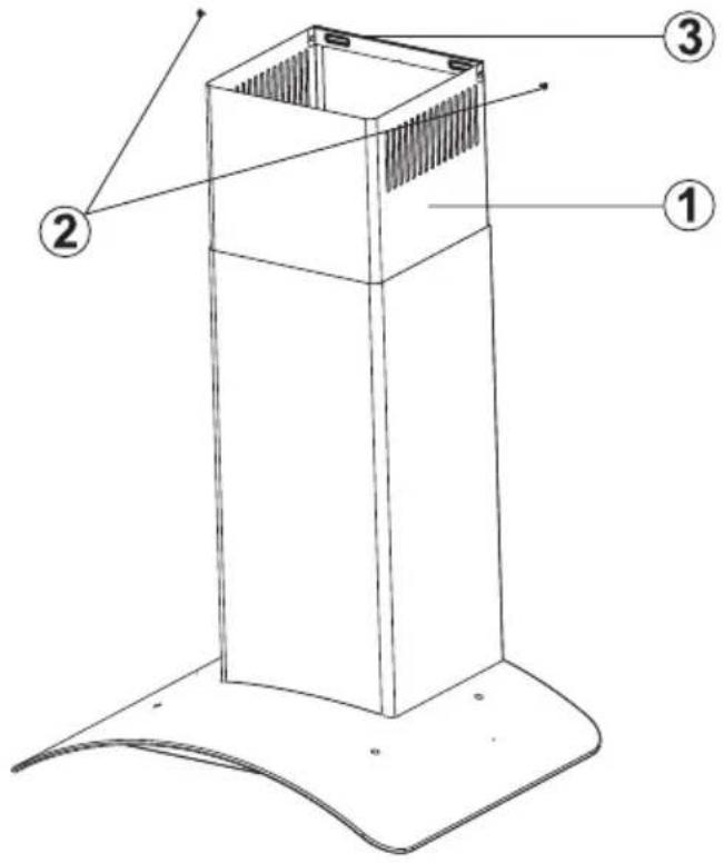
By pulling the inner flue (1) with screw (2) upwards and
left, screw it to the flue connection plate (3) on the right and left (Fig.12).
Fig. 12: ASSEMBLY OF PLATE FUELS
- Inner Flue
- Flue Connection Plate Fixing Screws
- Flue Connection Plate
The outer and inner sheet metal flues are assembled one within the other.
The cooker hood is set in the midst, and then the flue connecting plate (3) is directly affixed to the wall, under the cover or points E and F are marked after performing a measurement. (Page 16 Fig.10)
Drill points E and F with ∅6mm drill bit, and insert ∅6mm and plastic dowels. Insert the flue connection plate with 3.9x22 screws (Page 16 Fig.10)
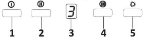
10 USE OF PRODUCT 10.1 On Glass 3 Spd Touch Button
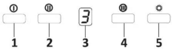
Fig. 11: Touch Button
- Press this button to turn on the product. When this button is pressed, product will also operate at speed level 1 (Fig.11).
- When this button is pressed, product will operate at speed level 2 (Fig.11).
- Dgt Display: You can see the operation rate of product on this screen (Fig.11).
- When this button is pressed, product will operate at speed level 3 (Fig.11).
- Press this button to turn on or off the lamp (Fig.11).

To activate timer function, press and hold any of buttons 1, 2 and 3 for 3 seconds. Then, 15 minute timer function will be activated and the product will turn off automatically after 15 minutes.
All active functions operated prior to activation of timer function will be deactivated after 15 minutes. All active functions operated after activation of timer function will be reactivated after 15 minutes.
10.2 Push Button
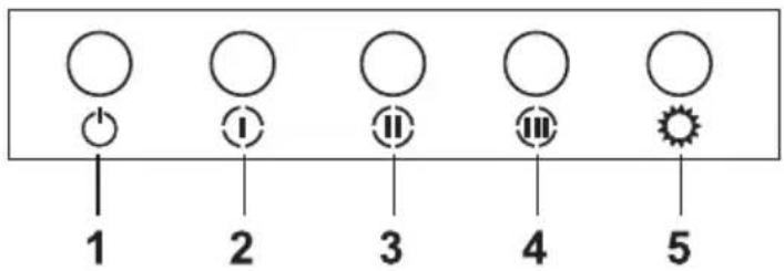
Fig. 12: Push Button
- Press this button to reset the product.
- When this button is pressed, product will operate at speed level 1.
- When this button is pressed, product will operate at speed level 2.
- When this button is pressed, product will operate at speed level 3.
- Press this button to turn on or off the lamp.
Cleaning Periods of the Metal Filter:
The filters must be cleaned when "C" signal appears on the display or (depending on usage) after every 2-3 weeks. When the filters are cleaned and mounted in their places, press button (①) for more than 3 seconds in order to delete "C" signal (when the product is inactive). Letter "E" will appear on the display, and the product will switch to normal operation. If it is desired to
go on operation without deleting "C" signal, active rate will appear for 1sec when ( Ⓤ button is pressed and then, "C" signal will reappear and motor will continue to operate.

"C" mark will appear at the end of the product's usage period of 60 hours.
11 REPLACEMENT OF LAMPS

DANGER
Disconnect the electrical supply of the cooker hood. Leave the lamps to cool down first because they could burn your hands when they are hot.
11.1 Replacement of Halogen Lamp
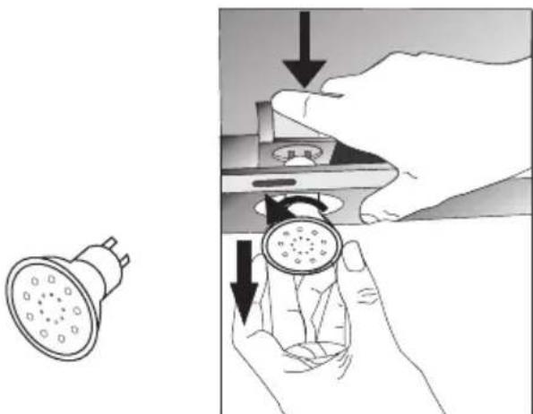
natural_image
Illustration showing a hand holding a showerhead and a close-up of the device with a circular component, both without any text or symbols.Fig. 13: Replacement of Halogen Lamp
Remove the aluminium cartridge filter. Remove the faulty bulb and replace with a new one with the same rating. Fig. 13
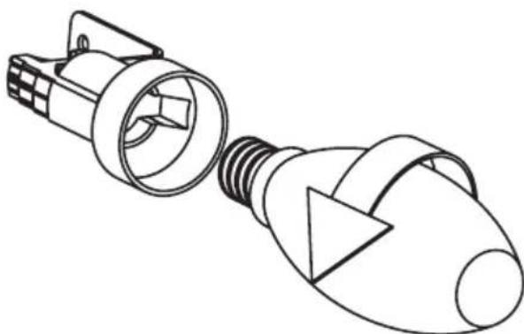
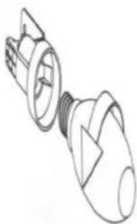
11.2 Replacement of Spark Plug Lamp
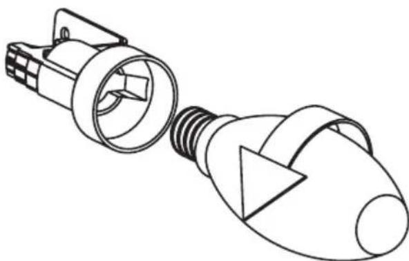
natural_image
Line drawing of a light bulb connector with internal components (no text or symbols)Fig. 14: Replacement of Spark Plug Lamp
Remove the aluminium cartridge filter. Remove the faulty bulb and replace with a new one with the same rating. Fig. 14
12 AUTHORIZED TECHNICAL SERVICE
If Lighting is Not Functioning:
■ Make sure that the plug is plugged in, and that the fuses are intact.
- Check the bulbs. Unplug the appliance without fail, when performing this control. Tighten the bulbs if they are loose, and replace them if they do not glow even after that process.
Possible Faults and What-to-Do Before
Calling the Technical Service:
A) If the appliance does not work in any way:
- Check to see if the cooker hood is plugged in or if the plug is fit properly into the socket.
■ Check the fuse, to which the appliance is connected, as well as the main fuse of your house.
If the performance of appliance is insufficient or it operates with too much noise:
- Is the outlet diameter of the appliance's flue adequate? (min.120 mm).
■ Are the metal filters clean? Control them.
■ If you use the cooker hood without flue, make sure that the carbon filters are not older than 6 months.
■ Be attentive to ventilate your kitchen adequately, in order to provide an airflow. If you are still not satisfied with the performance of the appliance, consult the authorized technical service.
12.1 Potential Failures and Solutions
| Description of Failure Reason Help | ||
| Appliance Does Not Work. | Check the power connection. | Mains voltage must be 220-240 V, and product must be plugged into a grounded socket. |
| Lighting Lamp Does Not Operate. | Check the power connection. | Mains voltage must be 220-240 V, and product must be plugged into a grounded socket. |
| Lighting Lamp Does Not Operate. | Check the power connection. | Lamp switch must be at "on" position. |
| Lighting Lamp Does Not Operate. | Check the bulbs. Bulbs must be operative. | |
| Product's Air Intake is Weak. | Check the aluminium filter. | The aluminium cartridge filter should be washed once a month under normal conditions. |
| Product's Air Intake is Weak. | Check the air outlet flue. | Air Outlet Flue Must Be Open. |
| Product's Air Intake is Weak. | Check the carbon filter. | In products that work with carbon filters, carbon filter must be replaced once in every 3 months under normal conditions. |
| It Does Not Discharge Air (in flueless use) | Check the aluminium filter. | The aluminium cartridge filter should be washed once a month under normal conditions. |
| It Does Not Discharge Air (in flueless use) | Check the carbon filter. | In products that work with carbon filters, carbon filter must be replaced once in every 3 months under normal conditions. |
12.2 Technical Table
| Supply Voltage 220 - 240 V 50Hz |
| Insulation Class of Motor F |
| Insulation Class CLASS I |

CGL 650IX / CGL 950IX
UPUTSTVA ZA UPOTREBU KUHINJSKI ASPIRATOR
MODEL: CGL650IX
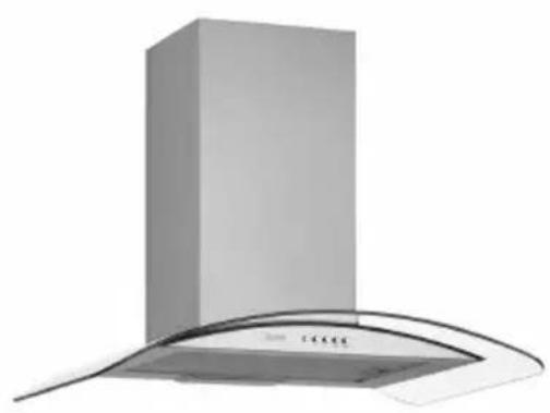
natural_image
Exterior view of a modern stainless steel kitchen chimney with curved roof (no text or symbols visible)MODEL: CGL950IX

natural_image
Exterior view of a modern kitchen air conditioner unit with a cylindrical top and curved cover (no text or symbols visible)Pažljivo pročitajte korisnički priručnik!
Sadržaj
1 TEHNIČKI CRTEŽ 4
2 UPOZORENJA I MERE BEZBEDNOSTI 5
2.1 Opasnost po život, opasnost od trovanja 7
2.2 Opasnost od strujnog udara! 7
2.3 Opasnost od fizičke povrede! 7
2.4 Opasnost od opekotina, opasnost od strujnog udara! 8
2.5 Opasnost od požara i fizičke povrede! 8
3 UPOTREBA SA ILI BEZ KARBON (UGLJENIK) FILTERA 9
3.1 Zamena karbon filtera 10
3.2 Zamena karbon filtera 10
4 ČIŠĆENJE I PREVENTIVNO ODRŽAVANJE 11
4.1 Pranje u mašini za sudove 11
4.2 Ručno pranje 11
4.3 Uklanjanje/ montaža aluminijum filtera 11
5 MONTAŽA UREĐAJA 12
5.1 Montaža i raspakivanje 12
5.2 Montaža i raspakivanje 12
5.3 Režim izduvavanja vazduha 13
5.4 Linija pražnjenja vazduha 13
5.5 Provera zida 13
5.6 Električni priključak 13
5.7 Opasnost od strujnog udara! 13
6 SADRŽAJ PAKETA 14
7 PREGLED KUHINJSKOG ASPIRATORA 15
8 SKLAPANJE PROIZVODA 16
8.1 Dijagram montaže i komponenata 16
8.2 Sastavljanje plastičnog ventilatora 17
9 SKLAPANJE PLOCASTIH VENTILATORA 18
10 UPOTREBA PROIZVODA 19
10.1 On Glass 3 Spd taster na dodir 19
10.2 Pritisni taster 19
11 ZAMENA LAMPI 20
11.1 Zamena halogene lampe 20
11.2 Zamena svećice 20
12 OVLASĆENI TEHNIČKI SERVIS 21
12.1 Potencijalni kvarovi i rešenja 22
12.2 Tehnička tabela 22
1 TEHNIČKI CRTEŽ
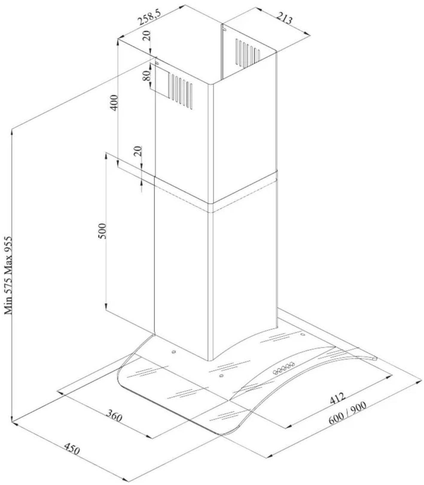
Slika 1: TEHNIČKI CRTEŽ
2 UPOZORENJA I MERE BEZBEDNOSTI
Slika 2: Opasnost od trovanja
natural_image
Simple line drawing of a house with a checkmark and airflow indicators (no text or symbols)Slika 3
! OPASNOST
Opasnost od požara!
Zbog varnica. Instalacija uređaja na grejnoj opremi koja se zagreva pomoću čvrstog goriva (npr. drvo ili ugalj) može biti dozvoljena samo ako postoji ne odvojiv poklopac. Potrebno je obratiti pažnju na postojeće građevinske propise i propise za lokalne kompanije za električnu energiju i gas prilikom montaže.
Ako uređaj nije očišćen u skladu sa uputstvima za čišćenje, može izazvati požar.
! OPASNOST
natural_image
Simple line diagram of a house with a central box and directional arrows, no text or symbols present.Slika 4: Izlaz za vazduh bez karbon filtera
⚠️UPOZORENJE
Rizik od smrti!

Izduvni gasovi koji se ponovno apsorbuju mogu izazvati trovanje. Izduvni vazduh ne sme da se prebacuje u ventilator za aktivan dim ili otpadne gasove; ili ventilator za ventilaciju prostora, tamo gde postoje montirani izvori grejanja.
■ Ako želite da prebacite izduvni vazduh u ventilator za aktivan dim ili otpadne gasove, morate dobiti dozvolu od ovlašćenih čistača dimnjaka.
■ Ako se izduvni vazduh ispušta kroz spoljni zid, Internet prodajnom centru mora se koristiti teleskopski zid.
Režim ventilacije vazduha

Apsorbovani vazduh se čisti filterima masti i filterom sa aktivnim ugljem, a zatim se prebacuje nazad u kuhinju. Slika 5
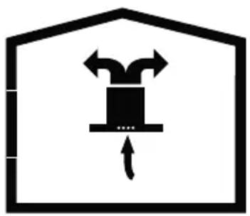
natural_image
Simple line drawing of a box inside a house-shaped frame with arrows indicating direction (no text or symbols)Slika 5: Izlaz za vazduh sa karbon filterom

Slika 6: karbon filter
Uređaj koji ste kupili je pogodan za upotrebu ugljenfiltera.
- Stavite karbon filter u njegovo kućište. Slika 6
- Okrenite karbon filter u pravcu kazaljke na satu i proverite da li je potpuno postavljen. Slika 6

Ako nije u potpunosti postavljen, karbon filter može da padne i ošteti proizvod.

OPASNOST
Nemojte prati karbon filtere. Držite karbon filter van domašaja dece.
4 ČIŠĆENJE I PREVENTIVNO ODRŽAVANJE
! OPASNOST
■ Pre svakog održavanja i čišćenja, aspirator mora biti isključen, kao i čitav aparat
- Čišćenje i održavanje ne smeju da vrše deca bez nadzora.
■ Površina može da se ošteti kao rezultat sredstva za čišćenje koja su agresivna i abrazivna. Nikad ne koristite sredstva za čišćenje koja su agresivna ili abrazivna. Nabavite sredstva za čišćenje i zaštitu koja su adekvatna za vaš proizvod od ovlašćenog servisa. Površina uređaja i komandne jedinice su osetljivi na ogrebotine.
■ Očistite površine mekom, vlažnom krpom, deterdžentom za sudove ili blagim sredstvom za čišćenje stakla. Omekšajte suvu, lepljivu prljavštinu vlažnom krpom. Nemojte strugati po uređaju!
■ Korišćenje suvih krpa, sundera koji mogu ogrebati uređaj, sredstava koja zahtevaju ribanje, sadrže pesak, sodu, kiseline, hlor ili druge jake supstance nije prikladna.
Slika 9: PREGLED KUHINJSKOG ASPIRATORA
- Unutrašnji ventilator
- Spoljašnji ventilator
- Staklo
- Osvetljenje aspiratora
- Kontrolna tabla
- Filter
8 SKLAPANJE PROIZVODA
8.1 Dijagram montaže i komponenata
Slika 10: MONTAŽA SKLOPA I KOMPONENATA
- Unutrašnji ventilator
- Spoljašnji ventilator
- Ploča za kačenje proizvoda
- Fiksirajući zavrtanj ploče za kačenje proizvoda
- Staklo
- 3x 5.5x60 zavrtanj za montiranje na zid
- 3x ∅10mm plastični ekser
- 2x 3.9x22 zavrtanj
- Ploča za povezivanje ventilatora
- 2x ∅6mm plastični ekser
■ Odvrćući zavrtanj ploče za kačenje proizvoda (4) povucite ploče za kačenje (3) na gore i fiksi- rajte viseću ploču ponovnim zavrtanjem fiksira- jućeg zavrtnja. Slika 10
■ Sastavite aspirator uz pomoć šeme za skla- panje. (Slika 8 / 7)
■ Pričvrstite šablon za sklapanje na zid, na određenoj visini (vidi minimalna i maksimalna odstojanja za radnu površinu u šablonu za skla- panje). Probušite tačke A, B i C.(Slika 10)
■ Ubacite ∅10mm tiplove (7) u rupe izbušene kao A, B, C i D, i zašrafite zavrtnje na mestima A + B, tako da 5mm prostora ostaje između glave šrafa i zida. (Slika 10)
■ Okačite ga na zid pomoću ploče za kačenje aspiratora.
■ Zategnite A + B zavrtnje na zidu i potpuno pričvrstite proizvod u tački C.
8.2 Sastavljanje plastičnog ventilatora
Slika 11: PLASTIČNI KONEKTOR VENTILATORA
16 slika 10)
Povlačenjem unutrašnjeg ventilatora (1) zavrtnjem (2) nagore i
levo, zavrnite ga na ploču za povezivanje ventilatora (3) sa desne i leve strane (strana 12).
Slika 12: SKLAPANJE PLOČASTIH VENTILATORA
- Unutrašnji ventilator
- Zavrtnji ploče za povezivanje ventilatora
- Ploča za povezivanje ventilatora
Unutrašnji i spoljašnji pločasti metalni ventilatori se ubacuju jedan u drugog.
Aspirator je postavljen u sredini, a zatim se ploča za povezivanje ventilatora (3) je direktno pričvršćuje za zid, pod poklopcem ili tačkama E i F koje su označene posle izvršenog merenja. (Strana 16 Slika 10)
Izbušite tačke E i F sa ∅6mm bušilicom i ubacite ∅6mm i plastične tiplove. Ubacite 3.9x22 zavrtnje ploče za povezivanje ventilatora (strana
10 UPOTREBA PROIZVODA 10.1 Na staklu 3 Spd pritisno dugme
Slika 11: Pritisnite taster
- Pritisnite ovaj taster da uključite proizvod. Kada je ovaj taster pritisnut proizvod će raditi na prvom nivou brzine (Slika 11).
- Kada je ovaj taster pritisnut proizvod će raditi na drugom nivou brzine (Slika 11).
- Digitalni displej: Možete videti stopu rada proizvoda na ovom ekranu (slika 11).
- Kada je ovaj taster pritisnut proizvod će raditi na trećem nivou brzine (Slika 11).
- Pritisnite ovaj taster da uključite i isključite lampu (Slika 11).

Da biste aktivirali tajmer funkciju, pritisnite i držite bilo koji od tastera 1, 2 i 3 na 3 sekunde. Tada, biće aktivirana funkcija tajmera od 15 minuta i proizvod će se automatski isključiti nakon 15 min.
natural_image
Illustration showing a hand holding a showerhead and a close-up of the circular component being inserted (no text or symbols present)Slika 13: Zamena LED lampe
Uklonite kertridž aluminijumskog filtera. Uklonite oštećenu sijalicu i zamenite je novom iste jačine. Slika 13.
11.2 Zamena svećice
natural_image
Line drawing of two light bulbs with internal components (no text or symbols)Slika 14: Zamena svećice
Uklonite kertridž aluminijumskog filtera. Uklonite oštećenu sijalicu i zamenite je novom iste jačine. Slika 14.
12 OVLAŠĆENI TEHNIČKI SERVIS
Ako osvetljenje ne radi:
natural_image
Exterior view of a modern stainless steel kitchen chimney with curved roof (no text or symbols visible)MODEL: CGL950IX
natural_image
Exterior view of a modern kitchen air conditioner unit with a cylindrical top and curved cover (no text or symbols visible)Pozorno preberite navodila!
Vsebina
- TEHNIČNA RISBA 4
- OPOZORILA IN VARNOSTNI UKREPI 5
2.1 Nevarnost smrtnih poškodb - Nevarnost zastrupitve 7
2.2 Nevarnost električnega udara 7
2.3 Nevarnost telesnih poškodb 7
2.4 Nevarnost opeklin, nevarnost el. udara 8
2.5 Nevarnost požara in telesnih poškodb 8 - UPORABA Z ALI BREZ OGLENEGA FILTRA 9
3.1 Menjava oglenega filtra 10
3.2 Menjava oglenega filtra 10 - ČIŠČENJE IN PREVENTIVNO VZDRŽEVANJE 11
4.1 Pranje v stroju za pomivanje posode 11
4.2 Ročno pranje 11
4.3 Odstranjevanje aluminijskega filtra 11 - MONTAŽA APARATA 12
5.1 Montaža in razpakiranje 12
5.2 Montaža in razpakiranje 12
5.3 Način delovanja 13
5.4 Odvodna napeljava 13
5.5 Preverjanje zida 13
5.6 Električni priključek 13
5.7 Nevarnost električnega udara 13 - VSEBINA EMBALAŽE 14
- PREGLED NAPE 15
- MONTAŽA APARATA 16
8.1 Shema montaže in delov 16
8.2 Nameščanje ventilatorja 17 - SESTAVLJANJE PLOŠČASTIH VODOV 18
- KAKO UPORABLJATI IZDELEK 19
10.1 Stikala 19
10.2 Stikala 19 - MENJAVA ŽARNIC 20
- POOBLAŠČENI SERVIS 21
1 TEHNIČNA RISBA
Slika 3
Zaradi tega je potrebno vedno zagotoviti ustrezen dotok svežega zraka.
! NEVARNOST
Nevarnost požara!
natural_image
Simple line drawing of a mechanical device inside a house frame, with no text or symbols present.natural_image
Simple line drawing of a box inside a house outline with directional arrows (no text or symbols)Slika 4: ogleni filter
Aparat, ki ste ga kupili, je primeren za uporabo z oglenim filtrom.
Slika 9: PREGLED NAPE
Slika 10: MONTAŽA IN DELI
Slika 11: PLASTIČNI SPOJ VENTILATORJA
-
∅120 mm adapter ventilatorja
-
»Telo« aparata
- Pričvrstite plastični ventilator (1) na telo aparata (2) in ga obrnite v smeri urinega kazalca (Slika 11).
• Namestite priključek zračnega odvoda na aparat.
9 MONTAŽA PLOŠČASTIH VODOV
Slika 11: MONTAŽA PLOŠČASTIH VODOV
natural_image
Illustration of a hand holding a device with a circular dial and an arrow indicating rotation (no text or symbols)Slika 12: Menjava halogenske žarnice Odstranite kaseto aluminijskega filtra. Odstranite odsluženo žarnico in jo zamenjajte z novo iste moči. Slika 12
11.2 Menjava žarnice
Slika 14: Menjava žarnice Odstranite kaseto aluminijskega filtra. Odstranite odsluženo žarnico in jo zamenjajte z novo iste moči. Slika 14
natural_image
Line drawing of a mechanical component with a bulb and screw (no text or symbols)12 POOBLAŠČENI SERVIS
natural_image
Exterior view of a modern stainless steel kitchen chimney with curved roof (no text or symbols visible)MODEL: CGL950IX
natural_image
Exterior view of a modern kitchen air conditioner unit with a cylindrical top and curved cover (no text or symbols visible)Pažljivo pročitajte korisničke upute!
Sadržaj
1 TEHNIČKI CRTEŽ 4
Slika 2: Opasnost od trovanja
natural_image
Simple line drawing of a house with a checkmark and airflow indicators (no text or symbols)Slika 3

OPASNOST
Opasnost od požara!
Zbog iskri, instalacija uređaja na grijnoj opremi koja se zagrijeva pomoću čvrstog goriva (npr. drvo ili ugalj) može biti dozvoljena samo ako postoji ne odvojiv poklopac. Potrebno je obratiti pažnju na postojeće građevinske propise i propise za lokalne kompanije za električnu energiju i plin prilikom montaže.
Ako uređaj nije očišćen u sukladu sa uputama za čišćenje, može izazvati požar.

OPASNOST
natural_image
Simple line diagram of a house with a central box and directional arrows, no text or symbols present.Slika 4: Izlaz za zrakbez karbon filtera
⚠️UPOZORENJE
Rizik od smrti!

Izduvni plinovi koji se ponovno apsorbuju mogu izazvati trovanje. Izduvni zrak ne smije da se prebacuje u ventilator za aktivan dim ili otpadne plinove; ili ventilator za ventilaciju prostora, tamo gdje postoje montirani izvori grijjanja.
■ Ako želite da prebacite izduvni zrak u ventilator za aktivan dim ili otpadne plinove, morate dobiti dozvolu od ovlaštenih čistača dimnjaka.
■ Ako se izduvni zrak ispušta kroz vanjski zid, mora se koristiti teleskopski zid.
natural_image
Simple black-and-white icon of a box inside a house-shaped frame with arrows indicating flow or movement (no text or symbols)Slika 6: karbon filtar
Slika 9: PREGLED KUHINJSKE NAPE
Slika 11: PLASTIČNI KONEKTOR VENTILATORA
- 120 mm adapter ventilatora
- „Tijelo“ uređaja
16 slika 10)
natural_image
Illustration showing a hand holding a showerhead and a close-up of its circular component being inserted (no text or symbols present)Slika 13: Zamjena LED žarulje
Uklonite kertridž aluminijskog filtera. Uklonite oštećenu žarulju i zamijenite je novom iste jačine. Slika 13.
natural_image
Line drawing of two light bulbs with internal components (no text or symbols)natural_image
Abstract black and white geometric pattern with diagonal stripes (no text or symbols)VOX
ELECTRONICS
PRT
CGL650IX / CGL950IX
MANUAL DE ISTRUÇÕES EXAUSTOR
MODEL: CGL650IX
natural_image
Exterior view of a modern stainless steel kitchen chimney with curved roof (no text or symbols visible)MODEL: CGL950IX
natural_image
Exterior view of a modern kitchen air conditioner unit with a cylindrical top and curved cover (no text or symbols visible)natural_image
Simple line drawing of a house with a chimney and a hanging device (no text or symbols)natural_image
Simple line drawing of a box inside a house-shaped frame with arrows indicating direction (no text or symbols)gura 10: MONTAGEM E PARTES
Ventilador interno
Ventilator externo
ura 11: CONECTOR DE PLÁSTICO DE VENTILADOR
11: MONTAGEM DOS VENTILADORES DE PLÁSTICO
natural_image
Illustration showing a lamp and a hand holding a dial with a downward arrow (no text or symbols)natural_image
Line drawing of a light bulb connector (no text or symbols)Figura
- CGL650IX / CGL950IX
- MODEL: CGL650IX
- MODEL: CGL950IX
- TECHNICAL DRAWING 4
- WARNINGS AND SAFETY PRECAUTIONS 5
- USAGES WITH AND WITHOUT CARBON FILTER 9
- CLEANING AND PREVENTIVE MAINTENANCE 11
- INSTALLATION OF APPLIANCE 12
- CONTENT OF PACKAGE 14
- OVERVIEW OF COOKER HOOD 15
- ASSEMBLY OF PRODUCT 16
- ASSEMBLY OF PLATE FUELS 18
- USE OF PRODUCT 19
- REPLACEMENT OF LAMPS 20
- AUTHORIZED TECHNICAL SERVICE 21
- TECHNICAL DRAWING
- WARNINGS AND SAFETY PRECAUTIONS
- Life-Threatening Danger, Poisoning Danger
- DANGER
- Fire danger!
- Danger of electric shock!
- Danger of physical injury!
- Danger of burn, danger of electric shock!
- Dangers of fire and physical injury!
- NOTE
- USAGES WITH AND WITHOUT CARBON FILTER
- Exhaust air mode
- WARNING
- Death Risk!
- Ventilated air mode
- Replacement of Carbon Filter
- Replacement of Carbon Filter
- CLEANING AND PREVENTI- VE MAINTENANCE
- Washing in Dishwasher
- Hand Wash
- Removal/Installation of Aluminium Filter
- INSTALLATION OF APPLIANCE
- Installation and Unpacking of the Appliance
- Recommendation for Energy Saving
- Exhaust Air Mode
- Air Discharge Line
- Circular Pipes
- Flat Channels
- ∅150 mm approx. 177 cm²
- ∅150 mm approx. 173 cm²
- Checking the Wall
- Electrical Connection
- Electric Shock Danger!
- Length of connection line: approx. 1.3 m
- Danger of Electric Shock!
- CONTENT OF PACKAGE
- OVERVIEW OF COOKER HOOD
- ASSEMBLY OF PRODUCT
- Installation Diagram and Components
- Assembly of Plastic Flue
- ASSEMBLY OF PLATE FUELS
- USE OF PRODUCT 10.1 On Glass 3 Spd Touch Button
- Cleaning Periods of the Metal Filter:
- REPLACEMENT OF LAMPS
- Replacement of Halogen Lamp
- Replacement of Spark Plug Lamp
- AUTHORIZED TECHNICAL SERVICE
- Possible Faults and What-to-Do Before
- Calling the Technical Service:
- A) If the appliance does not work in any way:
- If the performance of appliance is insufficient or it operates with too much noise:
- Potential Failures and Solutions
- Technical Table
- CGL 650IX / CGL 950IX
- UPUTSTVA ZA UPOTREBU KUHINJSKI ASPIRATOR
- Sadržaj
- TEHNIČKI CRTEŽ 4
- UPOZORENJA I MERE BEZBEDNOSTI 5
- UPOTREBA SA ILI BEZ KARBON (UGLJENIK) FILTERA 9
- ČIŠĆENJE I PREVENTIVNO ODRŽAVANJE 11
- MONTAŽA UREĐAJA 12
- SADRŽAJ PAKETA 14
- PREGLED KUHINJSKOG ASPIRATORA 15
- SKLAPANJE PROIZVODA 16
- SKLAPANJE PLOCASTIH VENTILATORA 18
- UPOTREBA PROIZVODA 19
- ZAMENA LAMPI 20
- OVLASĆENI TEHNIČKI SERVIS 21
- TEHNIČKI CRTEŽ
- UPOZORENJA I MERE BEZBEDNOSTI
- ! OPASNOST
- Opasnost od požara!
- ⚠️UPOZORENJE
- Rizik od smrti!
- Režim ventilacije vazduha
- OPASNOST
- ČIŠĆENJE I PREVENTIVNO ODRŽAVANJE
- Slika 9: PREGLED KUHINJSKOG ASPIRATORA
- SKLAPANJE PROIZVODA
- Dijagram montaže i komponenata
- Slika 10: MONTAŽA SKLOPA I KOMPONENATA
- Sastavljanje plastičnog ventilatora
- Slika 12: SKLAPANJE PLOČASTIH VENTILATORA
- UPOTREBA PROIZVODA 10.1 Na staklu 3 Spd pritisno dugme
- Zamena svećice
- OVLAŠĆENI TEHNIČKI SERVIS
- Vsebina
- TEHNIČNA RISBA
- ! NEVARNOST
- Slika 9: PREGLED NAPE
- Slika 10: MONTAŽA IN DELI
- MONTAŽA PLOŠČASTIH VODOV
- Slika 11: MONTAŽA PLOŠČASTIH VODOV
- Menjava žarnice
- POOBLAŠČENI SERVIS
- Slika 9: PREGLED KUHINJSKE NAPE
- VOX
- ELECTRONICS
- ura 11: CONECTOR DE PLÁSTICO DE VENTILADOR
Brand : VOX
Model : CGL 950 IX
Category : Range hood