
BVX120WTS - Ventilateur domestique GORENJE - Free user manual and instructions
Find the device manual for free BVX120WTS GORENJE in PDF.


| Product Type | Domestic exhaust fan with timer |
| Model | BVX120WTS |
| Brand | Gorenje |
| Voltage | 220-240 V / 50 Hz |
| Speed | 2100 rpm |
| Airflow | 120 m³/h |
| Power Consumption | 20 W |
| Diameter | 120 mm |
| Weight (estimated) | 1.5 kg |
| Mounting Options | Wall, ceiling, or window |
| Timer Delay | Adjustable from 1 to 25 minutes |
| Insulation Class | Class II (double insulation, no earth wire) |
| IP Protection | Use appropriate fittings for electrical cables |
| Max Room Temperature | 40°C |
| Min Mounting Height | 2.3 m from ground |
| Control | Supply voltage switch (bipolar switch with 3 mm contact gap) |
| Maintenance | Disconnect power before cleaning; do not use chemicals or immerse in water |
| Safety Features | Overheat protection, double insulation, no barefoot operation |
| Accessories Included | Mounting equipment, cable gland (outer cap not included) |
| Use | Domestic ventilation in bathrooms, kitchens, etc. |
Frequently Asked Questions - BVX120WTS GORENJE
User questions about BVX120WTS GORENJE
0 question about this device. Answer the ones you know or ask your own.
Ask a new question about this device
Download the instructions for your Ventilateur domestique in PDF format for free! Find your manual BVX120WTS - GORENJE and take your electronic device back in hand. On this page are published all the documents necessary for the use of your device. BVX120WTS by GORENJE.
USER MANUAL BVX120WTS GORENJE
FAN – INSTRUCTIONS FOR INSTALLATION AND USE
GB
VENTILATOR - UPUTE ZA MONTAZU I UPORABU
HR BIH
VENTILATOR - UPUTSTVO ZA MONTAŽU I UPOTREBU
SRB MK
natural_image
Three-panel image showing a white square air vent, a metallic square button, and a white ventilation grille (no text or symbols visible)Preberite ta navodila
natural_image
Illustration of a hand using a tool to adjust a component, with arrows indicating motion (no text or symbols present)MONTAŽA NA STEKLENO OKNO
natural_image
Technical line drawing of a ceiling structure with airflow indicators (no text or symbols)ELEKTRIČNA PRIKLJUČITEV
Before using the device for the first time, please read these instructions carefully and save them for future use.
FAN
INSTRUCTIONS FOR INSTALLATION AND USE
natural_image
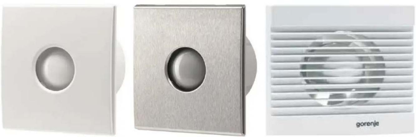
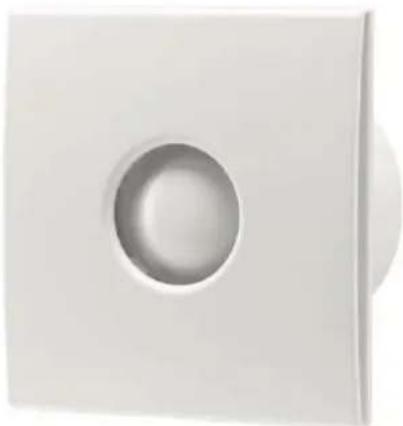
Three white air purifiers with circular cutouts and a metallic vent, shown from different angles (no text or symbols visible)Please read these instructions
They contain many useful tips on the proper use and maintenance of the fan.
SAFETY WARNINGS
- Remove the packaging and make sure the device is undamaged. In case of doubt, consult the service centre.
Keep the packaging out of the reach of children and persons with disabilities.
-
The device may only be used for applications specified in these instructions.
-
INSTALLATION
The device can be mounted on the ceiling, wall or window. Use the attached mounting equipment. The fan's exhaust must be vented out of the room or into the building's ventilation system.
Installation must be carried out by qualified personnel.
- ELECTRICAL CONNECTION
The fan motor must be connected to a single phase power supply as indicated on the nameplate. Connectors for the switch are located on the fan housing. To ensure adequate IP protection, use appropriate fittings for electrical cables. The fan must be securely mounted and connected with electric cables with minimum cross-section of 1 mm ^2 . The fan does not need an earth wire, as it is specified as a device with double insulation (class 2).
The device must be connected to the power supply by a qualified electrician. Connect the cable to the fan via a bipolar switch which must have a minimum spacing of 3 mm in all poles.
The device must be connected in accordance with national standards. Do not touch the device with moist or wet hands!
Do not touch the device while barefoot! Before cleaning or maintenance, turn off the mains power supply by means of the bipolar switch or disconnect the plug.
-
In the event of a breakdown or malfunction, switch off the device and do not tamper with it. If repairs are needed, please contact the service centre. Always insist on genuine spare parts
-
When the device is not in use, disconnect it from the mains power supply.
-
The maximum permitted temperature of the room where the device is installed is 40^ C.
-
The device should not be used unattended by children, disabled persons or persons with reduced capabilities.
Children should always be supervised to ensure they do not play with the device.
-
Do not use near flammable materials or their vapours (gasoline, alcohol, insecticides).
-
Prevent the inflow of flue gas in the room in the case of installed devices with an open combustion chamber
-
Do not modify the device.
-
Do not expose the device to weather conditions (rain, sun, etc.).
-
Inspect the device regularly. In the event of identified defects, stop using the device.
-
In the event of a fall or strong impact, the device must be checked by qualified personnel.
-
The room where the fan is installed must have an adequate supply of air to ensure efficient operation.
-
Do not cover the humidity sensor or motion sensor
MODELS
- Standard models
This model is turned on/off via a supply voltage switch.
Models: V-100, V-200, V-300, BVN ____ WS, BVX ____ SS, BVX ____ WS.
• Model with timer (T - timer)
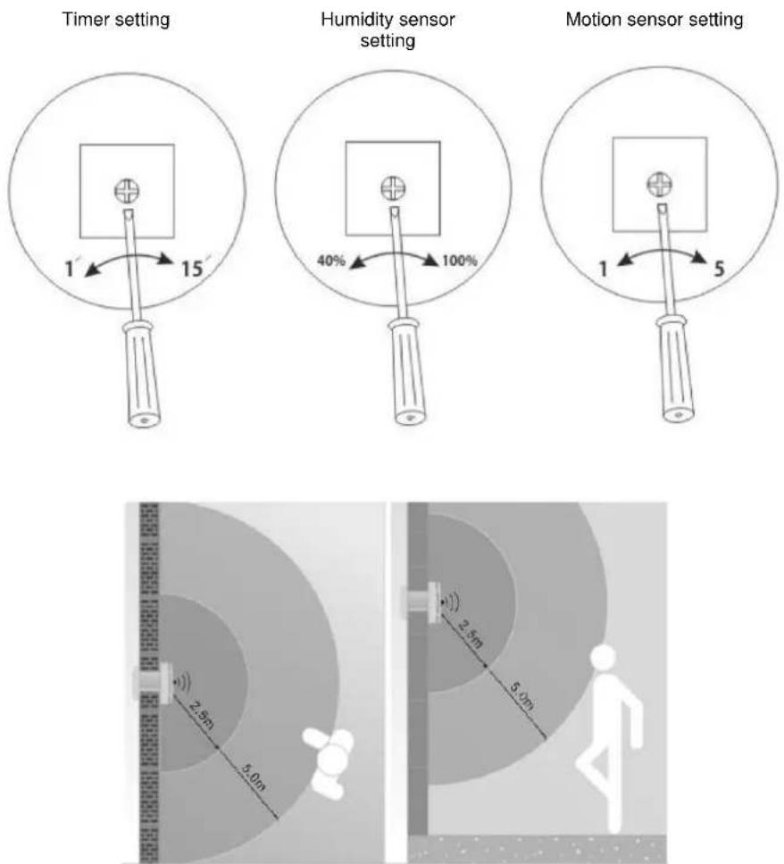
This model is equipped with a timer which allows the operation of the fan after turning off the switch. The default delay time is about 3 minutes. The timer can be set in the range from 1 to 25 minutes.
Models: BVX ____ WTS, BVX ____ STS.
• Model with humidity sensor (H - humidity)
This model is equipped with a humidity sensor that is activated when the relative humidity in the room exceeds the pre-set value. Possible adjustment is between 40% and 90%. This model is also equipped with a timer which allows power off delay ranging from 1 to 25 minutes.
Models: BVX ____ WHS, BVX ____ SHS.
- Module with a motion sensor to turn on the fan
The module is equipped with an infrared sensor which turns on the fan in case of detecting a person in the room. Sensitivity of person detection can be set between 1 and 5 m. This module is equipped with a timer which allows power off delay ranging from 1 to 25 minutes.
Model: BV MSS.
PLACEMENT AND MOUNTING
- Mount the fan as high as possible in the room. The minimum height is 2.3 m from the ground.
- Mount the fan opposite the main source of air that needs to be exchanged, at least 30 mm from the edge of the wall and ceiling.
- Mount the fan as close as possible to the source of vapour or odour, but far enough away that cannot be touched by a person in the shower or bath.
- If the fan is installed in a room with gas heating, electric heater, etc., the installer must ensure that there is sufficient replacement air to prevent the fan from sucking the air back through the cap (the cap can be supplied as additional equipment).
- Observe the national building laws.
WARNING: Before installation, the power supply must be disconnected.
NOTE: The electrical connection should be carried out by a qualified electrician.
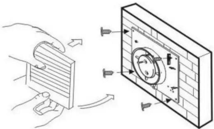
MOUNTING ON A WALL
- Before connecting to power supply, make sure that the voltage corresponds to the value indicated on the nameplate.
- Make sure that there are no water installations or electrical installations in the wall, and then prepare a hole of appropriate size. The channel should be slightly inclined towards the outer wall, thus enabling the discharge of any potential rainwater. Make a hole and wait for it to set before carrying out the connection.
- Remove the front fan cover. Place the fan on the wall and mark four points for mounting and the cable gland. Drill the holes.
- Connect the cable to the fan via a bipolar switch which must have a minimum spacing of 3 mm in all poles.
- Pull the cable through the cable gland and fix the fan to the wall.
- Replace the front cover and the outer cap (the outer cap is not included).
natural_image
Illustration of a hand using a tool to adjust or install a wall-mounted component, with no visible text or symbols.-
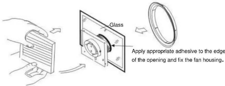
Before connecting to power supply, make sure that the voltage corresponds to the value indicated on the nameplate.
-
Check that there are no obstacles in the window, such as window frames, joints. Provide sufficient space for the housing.
-
Remove the front fan cover. Place the fan on the glass, mark and cut out the necessary opening.
-
Connect the cable to the fan via a bipolar switch which must have a minimum spacing of 3 mm in all poles.
-
Pull the cable through the cable gland and fix the fan to the wall.
-
Use the appropriate adhesive for fixing the fan housing to the glass surface.
-
Replace the front cover of the fan.
MOUNTING ON THE CEILING
-
Before connecting to power supply, make sure that the voltage corresponds to the value indicated on the nameplate.
-
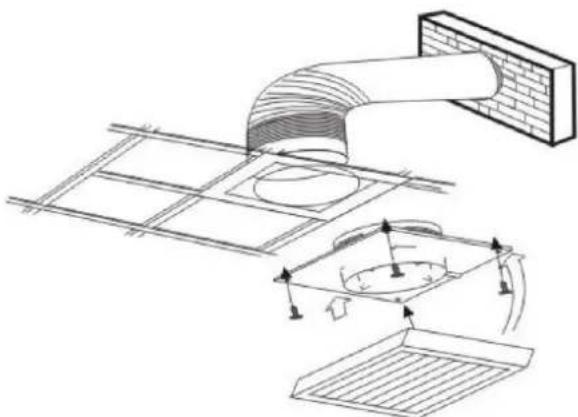
Select the appropriate location for the fan and cut out an appropriate opening.
-
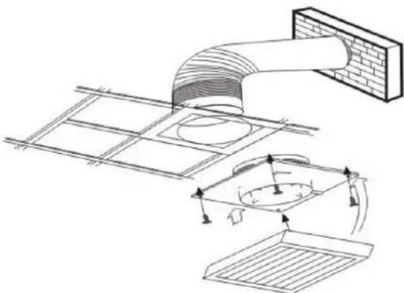
Remove the front fan cover. Place the fan on the ceiling and mark four points for mounting and the cable gland. Drill the holes.
-
Connect the cable to the fan via a bipolar switch which must have a minimum spacing of 3 mm in all poles.
-
Pull the cable through the cable gland and fix the fan to the ceiling.
-
Replace the front cover
-
The fan's exhaust must be vented out of the building through the ventilation pipes. Install the outer cap (not supplied).
natural_image
Technical line drawing of a ceiling structure with airflow indicators (no text or symbols)ELECTRICAL CONNECTION
- Fans have double insulation and do not require grounding
- In the fans mounted on partition walls, make sure that there are no gases returning into the room from heating appliances or any other appliances.
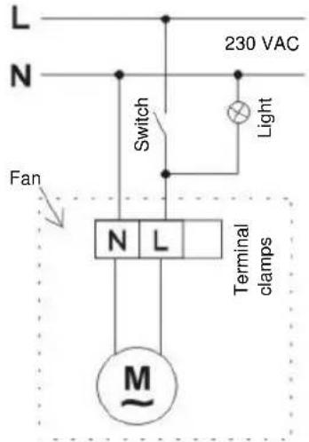
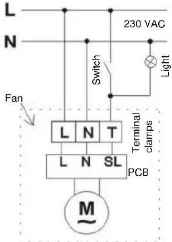
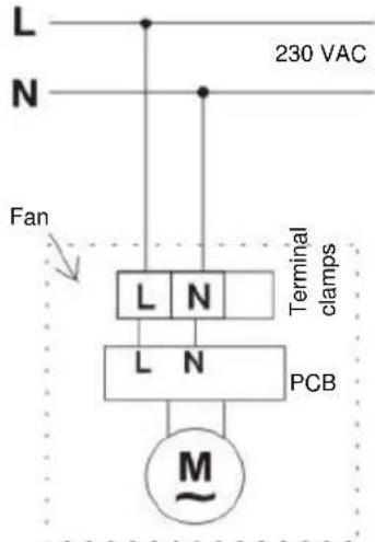
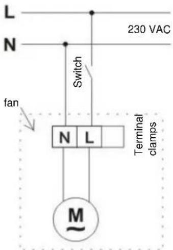
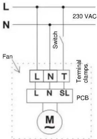
- L - connect the phase wire
N - connect the neutral wire
T - connect the voltage for the light or for the switch (fan with a timer or fan with humidity sensor)
Electrical wiring diagrams
With light:
Wiring diagram – standard models
Wiring diagram – models with timer / humidity sensor
Wiring diagram with motion sensor
Without light:
Wiring diagram – standard models
Wiring diagram – models with timer / humidity sensor
MAINTENANCE
- Before cleaning, turn off the fan.
- Do not use gasoline, benzene or any other chemicals.
- Make sure that water does not come into contact with electrical components such as switch or motor.
- Do not immerse blades or other parts made of synthetic resins, in water of more than 60^ C.
- Do not expose the fan to high temperatures and direct sunlight.
FEATURES
| MODEL | VOLTAGE (V/Hz) | SPEED (rot./min.) | AIR FLOW (m3/h) | POWER (W) | SIZE (mm) |
| Air flow 100 | 220-240/50 | 2450 | 100 | 15 | 100 |
| Air flow 200 | 220-240/50 | 2250 | 195 | 20 | 120 |
| Air flow 300 | 220-240/50 | 1450 | 320 | 25 | 150 |
| Diameter 100 White | 220-240/50 | 2300 | 70 | 15 | 100 |
| Diameter 100 White with timer | 220-240/50 | 2300 | 70 | 15 | 100 |
| Diameter 120 White with humidity / timer sensor | 220-240/50 | 2100 | 120 | 20 | 120 |
| Diameter 150 Stainless steel with humidity / timer sensor | 220-240/50 | 1600 | 210 | 25 | 150 |
| BV MSS* | 220-240/50 | / | / | / | / |
*Optional movement sensor for switching on Gorenje fans
HR, BIH
BVN ____ WS, BVX ____ WS, BVX ____ SS, BVX ____ WTS, BVX ____ STS, BVX ____ WHS, BVX ____ SHS, BV MSS
Prije prve uporabe klimatskog uređaja pozorno pročitajte ove upute i sačuvajte ih za buduću uporabu.
VENTILATOR
UPUTE ZA MONTAŽU I UPORABU
natural_image
Three white industrial air vent components: a square button with circular opening, a metallic square button with circular hole, and a high-temperature ventilation grille (no text or symbols visible)natural_image
Illustration of a hand installing a wall-mounted component next to a brick wall-mounted device (no text or symbols present)MONTAŽA NA ZIDNI PROZOR
-
Prije priključenja na dovod električne energije provjerite odgovara li napon vrijednosti koja je navedena na natpisnoi pločici.
-
Provjerite kako na prozoru ne bi bilo smetnji, poput prozorskih okvirova ili spojeva. Osiguraite dovolno prostora za kućište.
-
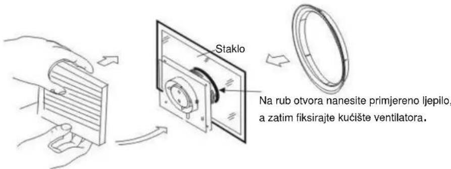
Skinite prednji poklopac ventilatora. Postavite ventilator na staklo, označite potreban izrez i izrežite potreban otvor.
-
Priključite kabel na ventilator preko dvopolnoga prekidača koji mora imati minimalni razmak od 3 mm na svim polovima.
-
Povucite kabel kroz kabelski uvodni element i pričvrstite ventilator na zid.
-
Koristite primiereno liepilo za fiksiranje kućišta ventilatora uz staklo.
-
Vratite natrag prednji poklopac ventilatora.
MONTAŽA NA STROP
-
Prije priključenja na dovod električne energije provjerite odgovara li napon vrijednosti koja je navedena na natpisnoj pločici.
-
Izaberite odgovarajuću lokaciju za ventilator te izrežite primieren otvor.
-
Skinite prednji poklopac ventilatora. Postavite ventilator na strop i označite četiri točke za pričvršćenje i kabelski uvodni element. Zatim izbušite rupe.
-
Priključite kabel na ventilator preko dvopolnoga prekidača koji mora imati minimalni razmak od 3 mm na svim polovima.
-
Povucite kabel kroz kabelski uvodni element i pričvrstite ventilator na strop.
-
Vratite natrag prednji poklopac.
-
Ispuh ventilatora treba biti sproveden izvan objekta preko ventilacijskih cijevi. Postavite vanjski zatvarač (nije priložen).
natural_image
Technical line drawing of a ceiling structure with airflow indicators (no text or symbols)ELEKTRIČNA INSTALACIJA
-
Ventilatori imaju dvostruku izolaciju i nije potrebno uzemljenje.
-
Za ventilatore koji su postavljeni na pregradne zidove valja paziti kako ne bi došlo do vraćanja plinova u prostoriju iz uređaja aparata za grijanje ili drugih aparata.
-
L - priključite na fazni vodič.
N - priključite na nulti vodič.
T - priključite na napon za svjetlo ili napon za prekidač (ventilator s tajmerom ili ventilator sa senzorom vlage).
UPUTSTVO ZA MONTAŽU I UPOTREBU
natural_image
White square wall-mounted air vent with a circular recess (no text or symbols)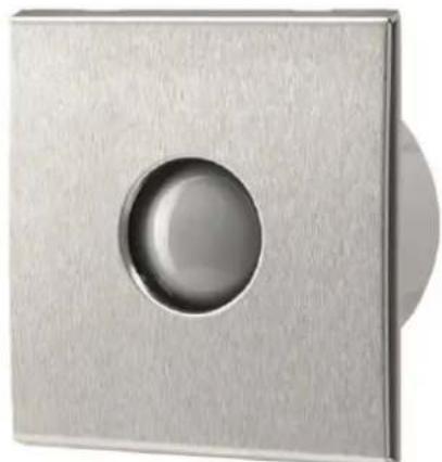
natural_image
Close-up of a metallic square button with a circular hole, no text or symbols visible.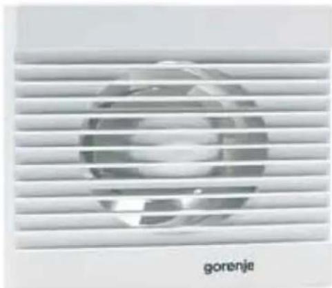
BEZBEDNOSNA UPUTSTVA
natural_image
Illustration of a hand installing or adjusting a wall-mounted component next to a brick wall-mounted panel (no text or symbols present)MONTAŽA NA STAKLENI PROZOR
-
Pre priključka na električnu energiju proverite da li napetost odgovara vrednosti koja je navedena na natpisnoi pločici.
-
Proverite da na prozoru nema prepreka kao što su prozorski okviri, spojevi. Obezbedite dovolino prostora za kućište.
-
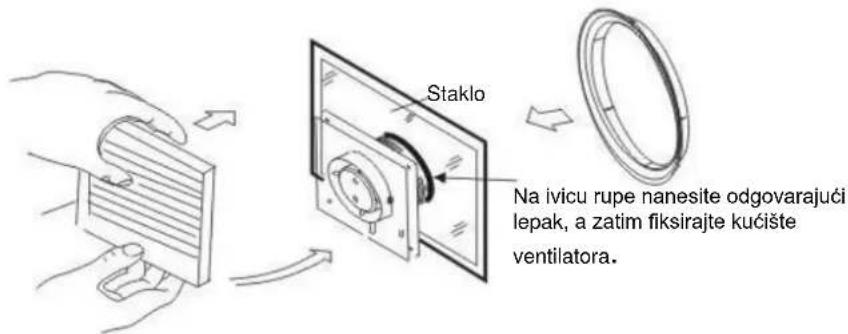
Odstranite prednji poklopac ventilatora. Postavite ventilator na staklo, označite potreban izrez i izrežite potrebni otvor.
-
Kabl priključite na ventilator preko dvopolnog prekidača koji mora da ima minimalni razmak od 3 mm na svim polovima.
-
Povucite kabl kroz kablovsku uvodnicu i pričvrstite ventilator za zid.
-
Upotrebite odgovarajući lepak za fiksiranje kućišta ventilatora na staklo.
-
Vratite nazad prednji poklopac ventilatora.
MONTAŽA NA PLAFON
-
Pre priključka na električnu energiju proverite da li napetost odgovara vrednosti koja je navedena na natpisnoj pločici.
-
Izaberite odgovarajuću lokaciju za ventilator i izrežite odgovarajuću rupu.
-
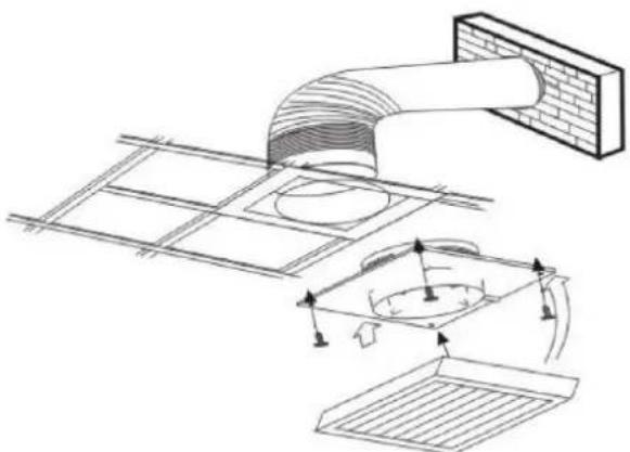
Odstranite prednji poklopac ventilatora. Postavite ventilator na plafon i označite četiri tačke za pričvršćivanje i kablovsku uvodnicu. Zatim izbušite rupe.
-
Kabl priključite na ventilator preko dvopolnog prekidača koji mora imati minimalni razmak od 3 mm na svim polovima.
-
Povucite kabl kroz kablovsku uvodnicu i pričvrstite ventilator za plafon.
-
Vratite nazad prednji poklopac ventilatora.
-
Ispuh ventilatora potrebno je izvesti van objekta uz pomoć ventilacionih cevi. Namestite spoljašnji zatvarač (nije priložen).
natural_image
Technical line drawing of a ceiling duct assembly with internal components and airflow indicators (no text or symbols)ELEKTRIČNI PRIKLJUČAK
-
Ventilatori imaju duplu izolaciju i nije im potrebno uzemljenje.
-
Kod ventilatora, montiranih na pregradnim zidovima, treba paziti da ne dođe do vraćanja gasova u prostor iz uređaja aparata za grejanje ili drugih aparata.
-
L - priključite na fazni provodnik.
N - priključite na nulti provodnik.
T - priključite na napetost za svetlo ili napetost za prekidač (ventilator sa časovnikom ili ventilator sa senzorom vlage).
Električne instalacione sheme
Sa svetlom:
Instalaciona shema – standardni modeli
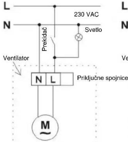
Instalaciona shema - mideli sa časovnikom / senzorom vlage
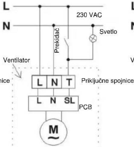
Instalaciona shema sa senzorom kretanja
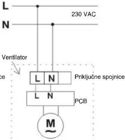
Bez svetla:
Instalaciona shema – standardni modeli
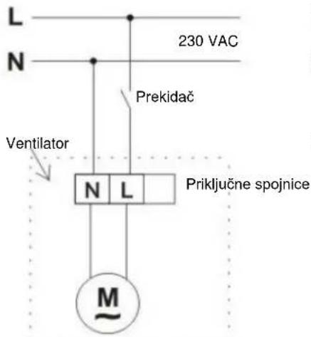
Instalaciona shema - mideli sa časovnikom / senzorom vlage
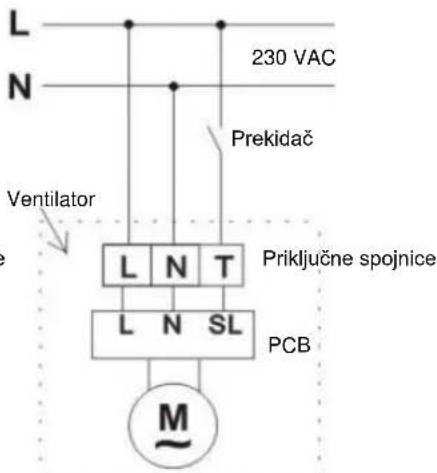
ODRŽAVANJE
- Pre čišćenja ventilator isključite.
- Za čiščenje ne koristite benzin, benzol ili bilo koje druge hemikalije.
- Pazite da voda ne dođe u kontakt sa električnim delovima, kao što je prekidač ili motor.
- Ne potapajte lopatice ili druge delove, izrađene iz veštačkih smola, u vodu koja ima više od 60°C.
- Ventilator ne izlažite visokim temperaturama i direktnoj sunčevoj svetlosti.
SVOJSTVA
| MODEL | NAPON (V/Hz) | BRZINA (okr./min.) | PROTOK VAZDUHA ( m^3/h ) | SNA GA (W) | VELIČINA (mm) |
| Protok 100 | 220-240/50 | 2450 | 100 | 15 | 100 |
| Protok 200 | 220-240/50 | 2250 | 195 | 20 | 120 |
| Protok 300 | 220-240/50 | 1450 | 320 | 25 | 150 |
| Diameter 100 Bijela | 220-240/50 | 2300 | 70 | 15 | 100 |
| Diameter 100 Bijela sa timerom | 220-240/50 | 2300 | 70 | 15 | 100 |
| Diameter 120 Bijela sa senzorom vlage / tajmerom | 220-240/50 | 2100 | 120 | 20 | 120 |
| Diameter 150 Metalni sa senzorom vlage / tajmerom | 220-240/50 | 1600 | 210 | 25 | 150 |
| BV MSS* | 220-240/50 | / | / | / | / |
*Opcioni senzor kretanja za uključivanje ventilatora Gorenje
Українська
BVN ____ WS, BVX ____ WS, BVX ____ SS, BVX ____ WTS, BVX ____ STS, BVX ____ WHS, BVX ____ SHS, BV MSS
natural_image
Three white air purifiers with circular cutouts and a metallic vent, shown from different angles (no text or symbols visible)natural_image
Illustration of a hand using a tool to install a wall-mounted component, with no visible text or symbols.natural_image
Technical line drawing of a ceiling structure with airflow indicators (no text or symbols)natural_image
Three white air purifiers with circular cutouts and a metallic vent, shown from different angles (no text or symbols visible)natural_image
Illustration of a hand using a tool to adjust a component, with a close-up view of a brick wall panel showing internal components (no text or symbols)natural_image
Technical line drawing of a ceiling structure with ductwork and ventilation system (no text or symbols)natural_image
Three white industrial air purifiers with circular cutouts and a metallic square cover, displayed against a plain background (no text or symbols visible)natural_image
Illustration of a hand using a tool to adjust or install a wall-mounted component, with no visible text or symbols.MONTAREA PE FEREASTRĂ
natural_image
Technical line drawing of a ceiling structure with airflow indicators (no text or symbols)CONEXIUNEA ELECTRICĂ
natural_image
Three white industrial air purifiers with circular cutouts, one with a square base and one with a fan grille (no text or symbols visible)Prečítajte si prosím tieto pokyny
natural_image
Diagram showing a hand installing a wall-mounted component next to a brick wall-mounted fixture with screw fasteners (no text or symbols present)MONTÁŽ NA OKNO
natural_image
Technical line drawing of a ceiling duct assembly with ventilation system (no text or symbols)ELEKTRICKÉ PRIPOJENIE
natural_image
Three white industrial air purifiers with circular cutouts and a metallic vent, shown from different angles (no text or symbols visible)natural_image
Illustration of a hand using a tool to adjust a wall-mounted component, with no text or symbols present.natural_image
Technical line drawing of a ceiling duct installation with ventilation grilles and fan components (no text or symbols)ЕЛЕКТРИЧЕСКО СВЪРЗВАНЕ
- Preberite ta navodila
- MONTAŽA NA STEKLENO OKNO
- ELEKTRIČNA PRIKLJUČITEV
- FAN
- INSTRUCTIONS FOR INSTALLATION AND USE
- Please read these instructions
- SAFETY WARNINGS
- MODELS
- PLACEMENT AND MOUNTING
- MOUNTING ON A WALL
- MOUNTING ON THE CEILING
- ELECTRICAL CONNECTION
- MAINTENANCE
- VENTILATOR
- UPUTE ZA MONTAŽU I UPORABU
- MONTAŽA NA ZIDNI PROZOR
- MONTAŽA NA STROP
- ELEKTRIČNA INSTALACIJA
- UPUTSTVO ZA MONTAŽU I UPOTREBU
- BEZBEDNOSNA UPUTSTVA
- MONTAŽA NA STAKLENI PROZOR
- MONTAŽA NA PLAFON
- ELEKTRIČNI PRIKLJUČAK
- Električne instalacione sheme
- Sa svetlom:
- Bez svetla:
- ODRŽAVANJE
- MONTAREA PE FEREASTRĂ
- CONEXIUNEA ELECTRICĂ
- MONTÁŽ NA OKNO
- ELEKTRICKÉ PRIPOJENIE
- ЕЛЕКТРИЧЕСКО СВЪРЗВАНЕ
Brand : GORENJE
Model : BVX120WTS
Category : Ventilateur domestique