416-116 - Air Conditioning Anslut - Free user manual and instructions
Find the device manual for free 416-116 Anslut in PDF.


| Product Type | Air/Water Heat Pump |
| Brand | Anslut |
| Model | 416-116 |
| Purpose | Heating and Cooling |
| Suitable Area | Up to 240 m² |
| Maximum Heating Capacity | 9 kW |
| Maximum Cooling Capacity | 8 kW |
| Power Consumption (Heating) | 1.05 - 2.8 kW |
| Power Consumption (Cooling) | 1.1 - 8.3 kW |
| Nominal Heating Capacity | 3.4 - 8.3 kW |
| Operating Range | -25 °C to +40 °C |
| COP (Coefficient of Performance) | Max 4.2 |
| Compressor Type | Panasonic Twin Rotary Inverter |
| Refrigerant | R410A |
| Sound Level Indoor Unit | 35 dB |
| Sound Level Outdoor Unit | 56 dB |
| Weight Indoor Unit | 26.5 kg |
| Weight Outdoor Unit | 48 kg |
| Indoor Unit Dimensions (W x D x H) | 450 x 220 x 645 mm |
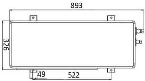
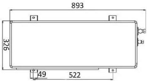
| Outdoor Unit Dimensions (W x D x H) | 893 x 380 x 706 mm |
| Supply Voltage | 230 V, 50 Hz, 16 A (earthed) |
| Electric Heater Cartridge | 3 kW (built-in, separate feed) |
| Defrost Function | Automatic and timer-set defrosting |
| Control Panel | Wired with LCD display, temperature setting, timer, night mode |
| Installation | Requires qualified technician |
Frequently Asked Questions - 416-116 Anslut
User questions about 416-116 Anslut
0 question about this device. Answer the ones you know or ask your own.
Ask a new question about this device
Download the instructions for your Air Conditioning in PDF format for free! Find your manual 416-116 - Anslut and take your electronic device back in hand. On this page are published all the documents necessary for the use of your device. 416-116 by Anslut.
USER MANUAL 416-116 Anslut
natural_image
Two white industrial air conditioning units with fan and control panel, one emitting a large fan (no visible text or symbols)SE Bruksanvisning för värmepump
NO Bruksanvisning for varmepumpe
PL Instrukcja obsługi pompy ciepta
EN User Instructions for heat pump
SE - Bruksanvisning i original
NO - Bruksanvisning i original
EN - Operating instructions in original
Date of production: 2014-07-14
© Jula AB
SVENSKA....4
SÄKERHETSANVISNINGAR....4
TEKNISK dATA 5
BESKRIVNING 6
Inomhusenhet 6
Utomhusenhet....7
MoNTERING 8
SAFETY INSTRUCTIONS....76
TECHNICAL DATA 77
dESCRIPITIoN 78
Indoor unit 78
Outdoor unit....79
INSTALLATION 80
Installation of Indoor Unit 82
Installing the outdoor unit 83
The control panel....89
Electric heater cartridge 95
Troubleshooting....96
SÄKERHETSANVISNINGAR
natural_image
Simple line drawing of a vertical rectangular container with small protrusions and a side outlet (no text or symbols)
natural_image
Pure technical diagram of a rectangular device with vertical and horizontal dimension lines, no text or symbols present.
natural_image
Pure electrical circuit lines without any symbols
UTomHUSENHET

Vätskerör: Ytterdiameter 3/8"
Gasrör: Ytterdiameter 1/2"


flowchart
graph LR
    1 --> 3
    2 --> 3
    3 --> 4
    4 --> 5
    5 --> 6
    6 --> 7
    7 --> 8
    8 --> 9
    9 --> 10
    10 --> 11
    11 --> 12
    12 --> 13
    13 --> 14
    14 --> 15
    15 --> 16
    16 --> 17
    17 --> 18
natural_image
Four-step diagram showing installation of a wall-mounted device with a tool, connected to a separate panel (no text or symbols present)INSTALLERA UTOMHUSENHETEN
natural_image
Technical illustration of a two-part industrial fan assembly with a cement block component, shown from different angles (no text or symbols on the diagram itself)natural_image
Four-panel technical diagram showing wall-mounted heating elements and mounting brackets, with no visible text or symbols.natural_image
Assorted automotive components including hoses, tires, and sensors (no visible text or labels)Håltagning
natural_image
Close-up of hands holding two cylindrical objects (no visible text or symbols)
natural_image
Close-up of hands using pliers to cut metal components (no visible text or symbols)VIKTIGT!
natural_image
Close-up of hands adjusting a mechanical component with wires and connectors (no visible text or symbols)
natural_image
Close-up of hands using a tool to adjust or install a mechanical component (no visible text or symbols)hattmuttern.
natural_image
Illustration of a credit card with a card slot and decorative border (no text or symbols)Ta bort frontpanelen.

natural_image
Illustration of a screwdriver inserted into a device with a cable (no text or symbols)natural_image
Illustration of a device with a pen and a slot, no text or symbols presentnatural_image
Illustration of a handheld electric shaver with a curved cable (no text or symbols)natural_image
Illustration of a screwdriver inserted into a device with a switch, next to an open electronic device (no text or symbols visible)natural_image
Diagram of a medical device with a cable and connector, no text or symbols presentnatural_image
Diagram showing a device connected to a card with a cable, no text or symbols presentflowchart
graph LR
    A["Sun"] --> B["Snow"]
    B --> C["Steam"]
    C --> D["Rightward Arrow"]
Ställa in timer AV
FROSTSKYDD
Nivå ett:

natural_image
Simple line drawing of a vertical rectangular container with small protrusions and a side outlet (no text or symbols)
natural_image
Technical line drawing of a rectangular industrial or electrical enclosure with vertical and horizontal dimension lines (no text or symbols)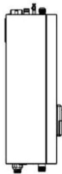
natural_image
Pure electrical circuit lines without any symbols
UTEDEL

Væskerør: Ytterdiameter 3/8"
Gassrør: Ytterdiameter 1/2"

flowchart
graph LR
    1["1 Tank"] --> 3["3 Tank"]
    2["2 Tank"] --> 3
    3 --> 4["4 Valve"]
    4 --> 5["5 Heat Exchanger"]
    5 --> 6["6 Heat Exchanger"]
    6 --> 7["7 Heat Exchanger"]
    7 --> 8["8 Valve"]
    8 --> 9["9 Heat Exchanger"]
    9 --> 10["10 Heat Exchanger"]
    10 --> 11["11 Valve"]
    10 --> 12["12 Heat Exchanger"]
    12 --> 13["13 Heat Exchanger"]
    13 --> 14["14 Heat Exchanger"]
    14 --> 15["15 Valve"]
    15 --> 16["16 Valve"]
    16 --> 17["17 Heat Exchanger"]
    17 --> 18["18 Heat Exchanger"]
natural_image
Four-step diagram showing installation of a wall-mounted device with a tool, mounted on a brick wall (no text or symbols present)INSTALLER UTEND∅RSENHETEN
natural_image
Technical illustration of two industrial fan units with base supports, one labeled 'Sementblokk' (no other text or symbols)natural_image
Four-panel technical diagram showing wall-mounted heating elements and mounting brackets, with no visible text or symbols.natural_image
Assorted automotive components including hoses, tires, and sensors (no visible text or labels)Hulltaking
natural_image
Close-up of hands holding two cylindrical objects (no visible text or symbols)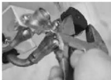
natural_image
Close-up of hands using pliers to handle metal components (no visible text or symbols)VIKTIG!
natural_image
Close-up of a hand adjusting a mechanical component with multiple wires (no visible text or symbols)
natural_image
Close-up of a hand holding a metallic tool, possibly a tool or connector, with no visible text or symbols.natural_image
Illustration of a credit card with a card slot and decorative border (no text or symbols)Ta av frontpanelet.

natural_image
Illustration of a handheld electronic device with a screwdriver and cable (no text or symbols)natural_image
Illustration of a device with a pen and a slot, no text or symbols presentnatural_image
Illustration of a handheld electric shaver with a curved wire and probe tip (no text or symbols)natural_image
Illustration of a screwdriver inserted into a device with a battery, next to an open electronic device (no text or symbols visible)natural_image
Diagram of a cable with a digital display connected to a terminal device (no text or symbols visible)natural_image
Diagram showing a device connected to a device with a cable, no text or symbols presentStille inn timeren AV
FROSTBESKYTTELSE
Nivå en:

natural_image
Simple line drawing of a rectangular container with ports and connectors (no text or symbols)
natural_image
Technical line drawing of a rectangular industrial or electrical enclosure with vertical and horizontal dimension lines (no text or symbols)
natural_image
Pure electrical circuit lines without any symbols
natural_image
Four-step diagram showing installation of a wall-mounted device with a tool, mounted on a brick wall (no text or symbols present)natural_image
Four-panel technical diagram showing wall-mounted door, vertical supports, and air vent assembly (no text or symbols)natural_image
Assorted automotive parts including hoses, tires, and sensors (no visible text or labels)Wykonywanie otworów
natural_image
Close-up of hands holding cylindrical objects, possibly mechanical parts or tools (no visible text or symbols)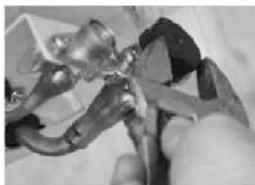
natural_image
Close-up of hands using pliers to cut metal components (no visible text or symbols)WAŻNE!
natural_image
Close-up of hands assembling electronic components with a tool (no visible text or symbols)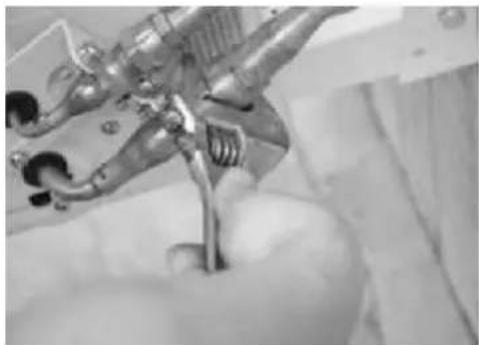
natural_image
Close-up of a hand holding a metallic tool or device with no visible text or symbolsnatural_image
Illustration of a credit card with a card slot and decorative border (no text or symbols)natural_image
Illustration of a portable electronic device with a screwdriver and cable (no text or symbols)natural_image
Illustration of a device with a pen and a slot, no text or symbols presentnatural_image
Illustration of a handheld electric shaver with a curved wire (no text or symbols)natural_image
Illustration of a screwdriver interacting with a device next to a computer monitor (no text or symbols visible)natural_image
Diagram of a medical device with a cable and connector, no text or symbols presentnatural_image
Diagram showing a device connected to a device with a cable, no text or symbols presentRead the User Instructions carefully before use
Please retain for future reference.
- The heat pump must not be used by anyone (including children) with reduced physical, sensory or mental capabilities, nor by anyone lacking experience and knowledge regarding the use of a heat pump, if they cannot get assistance or work under the supervision of a responsible person. Never allow children to play with the heat pump.
- The heat pump must be installed, disassembled and maintained by a technician. The design of the heat pump may not be modified in any way. Personal injury or material damage may result.
- Always disconnect the power supply before carrying out any work on the heat pump. A power cable that has become loose or damaged must be repaired by a technician.
- To protect the compressor, allow three minutes or more to pass between starting and stopping the heat pump.
- If the heat pump is to be used in combination with a shower, a mixing valve set to the correct temperature must be installed in front of the mixer. Be careful so that you do not scald yourself on the hot water.
- The fan may not be used in environments where inflammable substances are present or positioned where there is a major risk of corrosion.
- Do not connect other products to the same electrical outlet as for the heat pump and this can lead to problems.
- The heat pump must be connected to an earthed socket.
- Use the correct type of fuse and master switch. Steel and copper wire may not be used instead of a fuse or master switch. This could lead to serious injury/damage.
- Never cover the heat pump with clothes, plastic or other objects blocking the ventilation openings as this can result in the pump functioning poorly of not at all.
- Water or other liquids must not enter into the heat pump as this can lead to serious faults and cause irreparable pump damage.
- When the installation is complete, connect the heat pump to the power supply and check for any leakage current.
- Under no circumstances whatsoever may the earthing cable be connected to a radiator, gas or water pipe.
- Do not touch the air grille which the fan is in operation.
- The edge of the reel is sharp. Watch your fingers!
- A power cable that has become loose or damaged must be repaired by a technician.
- The heat pump must be connected to a system with a master switch. The power supply to the pump must match the specifications on the rating plate. Otherwise there is a major risk that the pump will be damaged.
- Disposal of used batteries - turn in used batteries to the Municipality's recycling centre or for battery recycling.
TEcHNl cAL dATA
| For dwellings up to 240 m2 | |
| Maximum heating capacity 9 kW | |
| Maximum cooling capacity 8 kW | |
| Power consumption for complete installation - heating 1.05 - 2.8 kW | |
| Power consumption for complete installation - cooling 1.1 - 8.3 kW | |
| Nominal heating capacity 3.4 - 8.3 kW | |
| Operating range -25 °C to + 40 °C | |
| Heat connection m3/h G 3/4" | |
| Air flow outdoor component 3,000 | |
| Max COP 4.2 | |
| Circulation pump for exchangers Built-in, class A | |
| Minimum water flow L/s 0.24 | |
| Nominal water flow L/s 0.395 | |
| Maximum water flow L/s 0.48 | |
| Defrost on demand option Yes | |
| Heating cable for defrosting | Yes |
| Preheating of compressor | Yes |
| Automatic additional electricity, when necessary | Yes |
| Electronic expansion valve Yes | |
| Compressor control Inverter | |
| Compressor | Panasonic Twin Rotary |
| Sound level indoor component | 35 dB |
| Sound level outdoor component | 56 dB |
| Weight indoor component | 26.5 kg |
| Weight outdoor component | 48 kg |
| Refrigerant | R410A |
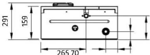
| Dimensions of indoor component w x d x h | 450 x 220 x 645 mm |
| Dimensions of indoor component w x d x h | 893 x 380 x 706 mm |
| Supply voltage, earthed** | 230 V, 50 Hz, 16 A |
| RCD and overload protection | Required |
| Electric heater cartridge, 3 kW | Yes, built-in (separate feed 230 V, 50 Hz, 16 A) |
Based in an outdoor temperature of +7 °C and a water temperature of +35 °C in accordance with SS-EN 14511-2007
*The figure is an estimation and depends in the degree of insulation and climate of the dwelling
**Slow fuse
dEScRIPTIoN
INdooR UNIT
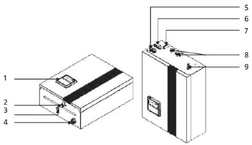
1 Control panel
2 Water outlet
3 Discharge
4 Water inlet
5 Cable gland
6 Quick connector
7 Refrigerant connector
8 Air vent

natural_image
Simple line drawing of a vertical rectangular container with small protrusions and a side outlet (no text or symbols)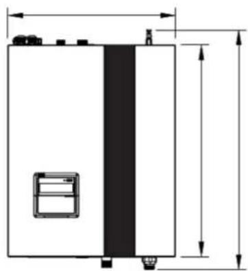
natural_image
Technical line drawing of a rectangular industrial or electrical enclosure with dimension lines (no text or symbols)
natural_image
Simple line drawing of a rectangular container with ports and side connectors (no text or symbols)
OUTDOOR UNIT

Liquid pipe: External diameter 3/8" Gas pipe: External diameter 1/2"


flowchart
graph LR
    1 --> 3
    2 --> 3
    3 --> 4
    4 --> 5
    5 --> 6
    6 --> 7
    7 --> 8
    8 --> 9
    9 --> 10
    10 --> 11
    11 --> 12
    12 --> 13
    13 --> 14
    14 --> 15
    15 --> 16
    16 --> 17
    17 --> 18
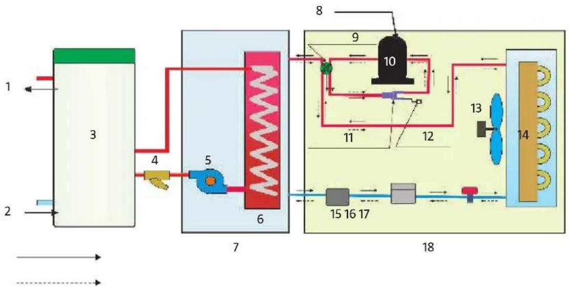
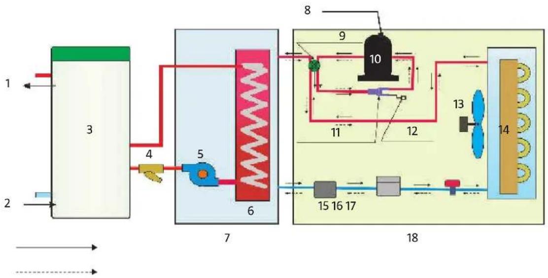
1 Hot water outlet 10 Compressor
2 Cold water outlet 11 Three-way valve
3 Water tank 12 Check valve
4 Water filter 13 Fan motor
5 Water pump 14 Evaporator
6 Heat exchanger 15 Refrigerant
7 Indoor unit 16 Filter
8 Power supply 17 Expansion valve
9 Four-way valve
18 Outdoor unit

A Air intake
B Air outlet
C Second refrigerant pipes
INSTALLATION
Area of application 1
Air/water heat pump + boiler (high)
The heat pump must be installed by a qualified installer.

flowchart
graph TD
    A["Tap water"] --> B["Hot water"]
    B --> C["Oil boiler"]
    C --> D["4"]
    D --> E["6"]
    E --> F["7"]
    F --> G["5"]
    G --> H["10"]
    H --> I["Outdoor unit"]
    C --> J["3"]
    J --> K["9"]
    K --> L["4"]
    L --> M["Element"]
    style A fill:#f9f,stroke:#333
    style B fill:#ccf,stroke:#333
    style C fill:#cfc,stroke:#333
    style D fill:#fcc,stroke:#333
    style E fill:#cff,stroke:#333
    style F fill:#ffc,stroke:#333
    style G fill:#cfc,stroke:#333
    style H fill:#fcc,stroke:#333
    style I fill:#ccf,stroke:#333
    style J fill:#cfc,stroke:#333
    style K fill:#fcc,stroke:#333
    style L fill:#cfc,stroke:#333
    style M fill:#fcc,stroke:#333
    style_N["Flexible Pipe, 50 cm"] --> O["1"]
    N --> P["2"]
No.: Name Symbol
| 1 Shut-off valve | |
| 2 Filter | |
| 3 Three-way shunt | |
| 4 Water pump | |
| 5 Expansion tank | |
| 6 Manometer | |
| 7 T/P valve for solar power systems | |
| 8 Automatic air valve | |
| 9 Mixing valve | |
| 10 Room sensor |
Range
| Low | 25 - 40 °C |
| Medium | 40 - 50 °C |
| High | 50 - 80 °C |
Distribution system temperature
Area of application 2
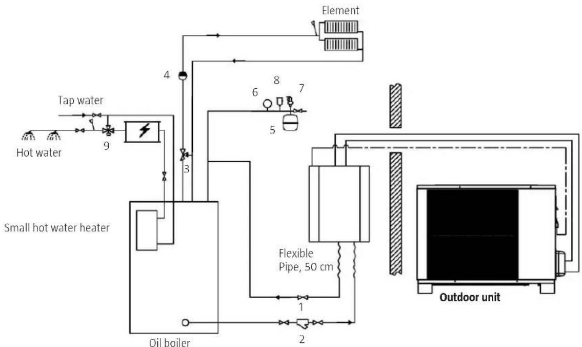
Air/water heat pump + boiler + small water heater connected in series with an oil boiler.
The heat pump must be installed by a qualified installer.
flowchart
graph TD
    A["Hot water"] --> B["Tap water"]
    B --> C["Small hot water heater"]
    C --> D["Oil boiler"]
    D --> E["Flexible Pipe, 50 cm"]
    E --> F["Outdoor unit"]
    G["Element"] --> H["4"]
    H --> I["3"]
    I --> J["6"]
    I --> K["7"]
    I --> L["5"]
    M["1"] --> N["2"]
    N --> O["2"]
    P["8"] --> Q["7"]
No.: Name Symbol
| 1 Shut-off valve | |
| 2 Filter | |
| 3 Three-way shunt | |
| 4 Water pump | |
| 5 Expansion tank | |
| 6 Manometer | |
| 7 T/P valve for solar power systems | |
| 8 Automatic air valve | |
| 9 Mixing valve |
Range
| Low | 25 - 40 °C |
| Medium | 40 - 50 °C |
| High | 50 - 80 °C |
Distribution system temperature
INSTALLATION OF INDOOR UNIT
We recommend that the indoor unit be installed in or in close proximity to the boiler room. Ask a HVAC expert for help in finding an optimal location in relation to the existing heating system. We recommend that flexible hoses be used for connecting to the outdoor unit. The control panel can be located anywhere in the house. If the control panel is to be used to regulate the temperature based on the current room temperature, it should be placed in the room where it is most important to maintain the correct temperature.
Installation notes
A. The indoor unit must be place indoors and be mounted on the wall with the water outlet facing downwards.
B. Place the indoor unit in a dry, well-ventilated location.
C. The indoor unit may not be installed in an environment where there inflammable substances such as gases or where corrosion easily occurs.
D. We recommend that the indoor unit be installed close to the central HVAC installation.
E. Leave sufficient free space around the indoor unit so that it is easily accessible for maintenance. Choose a suitable installation site for the indoor unit in accordance with the following guidelines:
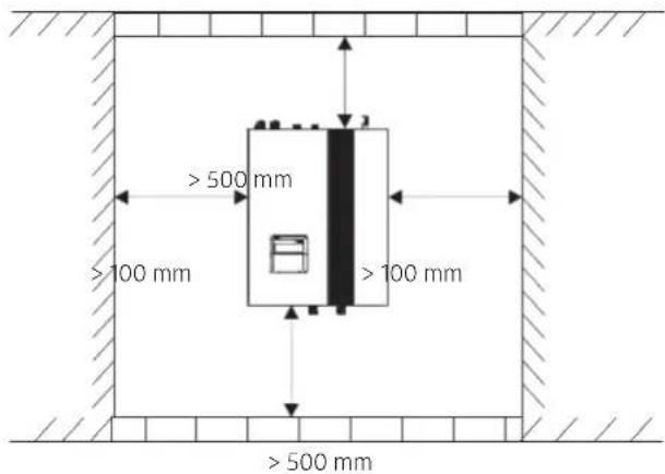
Installation
The indoor unit must be mounted in a stable wall in accordance with the following instructions:
- Take the expansion bolts and the wall bracket for the indoor unit out from the accessory package. Hold the wall bracket horizontal to the wall. Mark the position for the drill holes by using the holes in the wall bracket as a template.
- Drill holes using a suitable diameter for the expansion bolts.
- Knock the expansion bolts into the drill holes and screw the wall bracket on securely.
- Suspend the indoor unit on the wall bracket and make sure it is securely attached before letting go.
- The installation is now complete.
TIP:
If the heat pump is to be mounted on a wooden wall, use self-tapping screws instead of expansion bolts. Screw the wall bracket directly onto the wooden wall without first drilling holes. The wooden wall must be sufficiently stable. The heat pump must not be mounted on an unstable wooden wall.

natural_image
Four-step diagram showing installation of a wall-mounted device with a tool, mounted on a brick wall (no text or symbols present)INSTALLING THE OUTDOOR UNIT
The wall bracket, vibration absorbers and screws for cement/concrete walls are used to install the outdoor unit. The pipe section belonging to the outdoor unit are filled and equipped with threaded connections including check valves.
Installation notes
A. The outdoor unit can be placed in a patio, on a balcony, on the roof or suspended on an outer wall.
B. The indoor unit must be placed on a dry and well-ventilated site. If the outdoor unit is installed in a damp environment, the electric components can start to corrode and/or become short-circuited.
C. The outdoor unit must not be installed in an environment where inflammable substances such as gases exist or where corrosion easily occurs.
D. Do not install the outdoor unit in the vicinity of a bedroom or living room as it gives off a sound when in operation.
E. If the outdoor unit is installed in a region where there are minus degrees, snow or a high level of humidity, it must be mounted approx. 50 cm above ground level. We recommend that a protective cover be mounted of the outdoor unit so that snow does not clog the air openings.
F. Select a site with a good run-off so that the condensing water that occurs during defrosting does not cause problems.
G. The outdoor unit must be installed with a slight gradient (1 cm/m) so that rain water will run off.
H. The outdoor unit should be installed at a justifiable distance from any range hood valve to avoid cooking fumes from penetrating and attaching themselves to the heat exchanger, which will subsequently be very difficult to clean.
1. Do not install the indoor or outdoor unit in damp places since the can lead to some components short-circuiting or rusting. The outdoor unit must not be placed in a damp and corrosive environment. Otherwise, there is a risk that its service life will be shortened.
J. Make sure that there is sufficient free space around the outdoor unit so that ventilation is good and it is easy to get to the unit for maintenance. Look at the following picture,

Installation on the ground
In order to avoid large amounts of run-off water from the outdoor bringing with it the risk of re-freezing after defrosting, it should be placed on the accompanying stand. Consider the following during installation
A. The ground should be smooth and flat.
B. The stand should hold a weight equivalent to five time the weight of the outdoor unit.
C. The stand should be screwed tight using all associated screws since the outdoor unit might otherwise fall down and be damaged.
D. The outdoor unit must be properly attached to the stand.
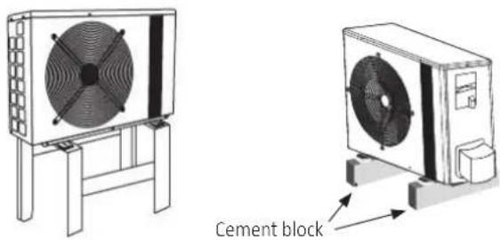
natural_image
Technical illustration of a two-tiered industrial fan unit with a cement block connection (no text or symbols on the diagram itself)E. The outdoor unit can also be placed on a cement block. The height of the cement block must be at least 500 mm, and the unit must be fixed to the block in a justifiable manner.
Wall installation
- Take the wall brackets from the accessory package. Measure carefully so that the distance between the brackets it the same as between the feet of the outdoor unit.
- Screw tight the wall brackets using the accompanying expansion bolts.
- Place the vibration absorber on the wall brackets. This will reduce noise and vibrations from the outdoor unit.
- Screw tight the outdoor unit and the vibration absorber on the wall brackets.

natural_image
Four-panel technical diagram showing wall-mounted heating elements and mounting brackets, with no visible text or symbols.Refrigerant pipes and the signal cable connecting the indoor and outdoor units should be run through the wall via a lead-through. The hole should lean slightly towards the outside (approx. an 8 degree angle) to avoid rain and condensing water from running in.

cable installation
- A suitable master switch should be used for the heat pump.
- The heat pump must be connected to an earthed electrical socket.
- The electric connection must be performed by an authorised electrician.
- Cable pulling must be carried out in accordance with applicable laws and regulations.
- The electric connection must be carried out with the heat pump turned off.
- The power cable must be properly attached and must not become loose.
- Never splice power cables.
- Check that the power supply corresponds to the information on the heat pump rating plate.
- Check that the power supply, the power cable and the electric outlet meet the heat pump's power requirements.
Power cable between the indoor and outdoor unit
Think about the following when installing the power cable between the indoor and outdoor unit (the power cable is in the same package as the pipe kit):

Remove the small hatch on the outdoor unit and connect the cable with the quick connector.
Connect the other end of the cable to the quick connector on the top of the indoor unit.
Installation kit
The installation kit includes 2 gas-filled pipes, a drain hose, a sealant, PE tape, insulation, straps and a power cable with connectors suitable for the indoor and outdoor unit. Please note that the drain hose is only used fro air/air heat pumps, not air/water heat pumps.
NOTE: Do not remove the plastic plugs from the pipes until the installation has started.

natural_image
Assorted automotive components including hoses, tires, and sensors (no visible text or labels)Hole-making
Use appropriate tools to investigate that the outer wall is free from obstructions (concrete reinforcement, cables etc.) where screw can be tightened.
- Screw the wall bracket onto the wall. Then use an appropriate hole punch to make a hole approx. 80 mm in diameter (depending on the size of the accompanying lead-through) in the wall.
- Saw/drill at low speed to avoid overheating. Pre-drill if you want with a 12-15 mm drill because this can facilitate hole-making.
Piping and wiring
When both the indoor and outdoor units have been mounted, secondary refrigerant pipes and electric wiring must be routed between them. Disconnect the bottom of the indoor unit to simplify the installation (does not apply to 416107/416116). The power cable is equipped with a connector for simple connection to the indoor unit. Plug the connector into the outlet and attach the cable in the cable holder. Never connect the heat pump to the power supply before the pipes have been connected and all units have been connected together. Press the lead-through in the wall from the outdoor side. Then press in the sealing ring and secure it.
Pull the secondary refrigerant
Begin with the indoor activity, and gradually straighten the pipes. There are cap nuts on the ends of pipes that are used to connect the pipes to the permanently mounted pipes on each respective unit. It is impossible to attach the cap nuts incorrectly. Use the one spanner as a dolly and the other for tightening the cap nut (a dolly is required to prevent the nut from being damaged).
Connect the pipes (from the installation kit) to the couplings within the indoor unit. First tighten the pipe couplings by hand, and then tighten them with the spanners. Tighten the couplings properly. A hissing sound will be heard. Use the one spanner as a dolly and the other to tighten the cap nut.
Tighten to no more than 18 Nm. If uncertain, use a torque wrench- Do not screw tight the fixed connectors on the indoor and outdoor unit. Always use the one spanner as a dolly when connecting the couplings. If you do not do this, the couplings themselves can be turned round and become destroyed. Retighten the couplings 24 hours after the installation has been completed.

natural_image
Close-up of hands holding two cylindrical objects (no visible text or symbols)
natural_image
Close-up of hands using pliers to cut metal components (no visible text or symbols)IMPORTANT!
The pipes in the installation kit are prefilled with gas and may not be cut under any circumstances. Do not remove the plastic plugs from the pipes before it is time to mount them. If the pipes are deformed and leaking, loosen the pipe caps from the couplings. The check valves now close.
Pull the pipes from the indoor to the outdoor unit and connect them to the outdoor unit in the same way as described above. The secondary refrigerant pipes should not be bent to a radius less than 15 cm (check with a template). Pull the power cable along with the pipes. Bend the pipes carefully, little by little. The pipe bends must not be too sharp.
Mounting the installation kit
- There are cap nuts on the ends of the pipes that are used for connecting the pipes to the fixed pipes on the outdoor unit.
- It is impossible to attach the cap nuts incorrectly. Use the one spanner as a dolly and the other for tightening the cap nut (a dolly is required to prevent the nut from being damaged).
- Connect the pipes (from the installation kit) to the couplings on the outdoor unit. First tighten the pipe couplings by hand, and then tighten them with the spanners.

natural_image
Close-up of a hand adjusting electrical components with wires (no visible text or symbols)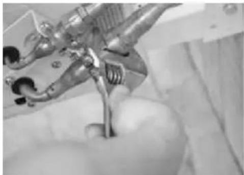
natural_image
Close-up of a hand holding a metallic tool, possibly a robotic arm or tool, with no visible text or symbols.- Tighten the couplings properly. A hissing sound will be heard. Use the one spanner as a dolly and the other to tighten the cap nut.
- Do not tighten the fixed couplings. Always use the one spanner as a dolly when connecting the couplings. If you do not do this, the couplings themselves can be turned round and destroyed.
- Retighten the couplings 24 hours after the installation has been completed.
Connecting the water pipes
Once the outdoor unit has been installed, the incoming and outgoing water pipes must be connected in accordance with applicable regulations and diagrams in these user instructions. The correct type of water pipes must be selected and handled in the correct manner. After connection, the water pipe must be pressure tested and cleaned before the system is taken into operation.
All hot water pipes must be well insulated. Insulation must be properly sealed and there must not be any openings (However, safety valves must not be covered; they must be accessible for maintenance).
INSULATION Make sure that the water pressure is sufficiently high to transport the water to the necessary height. If the water pressure is not high enough, add a water pump to the system in increase the head.
WATER FILTER A filter (20 meshes/cm ^2 ) should be installed at the inlet to the water cistern and the indoor unit. This will prevent particles from penetrating and provide a better quality of water.

Installing the control panel
If you want to mount the control panel on to the wall, take the communication cable out of the accessory package and do as follows:

natural_image
Illustration of a credit card with a card slot and decorative border (no text or symbols)Remove the front panel.
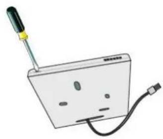
natural_image
Illustration of a portable electronic device with a screwdriver and cable (no text or symbols)Insert a screwdriver in the opening on the side of the control panel to open it.
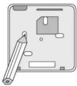
natural_image
Illustration of a flat-screen electronic device with a pen and internal components (no text or symbols)Use the rear of the control panel as a template to draw where the holes in the wall are to be drilled.

natural_image
Illustration of a handheld electric shaver with wires (no text or symbols)Drill the holes as per your markings.

natural_image
Illustration of a screwdriver inserted into a device with a battery, next to an open electronic device (no text or symbols visible)Pull the communication cable through the rear cover and then screw it onto the wall. Attach the front of the control panel.

natural_image
Diagram of a medical device with a cable and connector, no text or symbols presentUse the rear of the control panel as a template to draw where the holes in the wall are to be drilled.

natural_image
Diagram showing a device connected to a device with a cable, no text or symbols presentPull the communication cable to the indoor unit, direct it through the opening in the front panel and connect the quick connector to the printed circuit board. Reinstall the front panel.
Check before initial start
Before starting the heat pump, check the following:
- Check that the water pipes are properly tightened and that there is no leakage.
- Check that the valves for incoming water are open and that the water is coming through.
- Check whether the power cable is correctly connected and that the system is earthed.
- Check that the indoor and outdoor unit are properly secured in the correct position.
- Check that the power supply matches the specifications on the rating plate.
- Check that the water supply is working correctly and there is risk for freezing.
- Check that the secondary refrigerant pipes and water pipes are well-insulated.
The heat pump can now be started. If any of the aforementioned checks require that actions be taken, these must be implemented before the heat pump is started.
Checks before starting
- When the units have been mounted, the water pipes have been connected and venting and leakage checks have been carried out without problems, power can be connected and the system started.
- Start the heat pump by pressing the on/off button on the control panel. Pay attention to abnormal noise and vibrations during start-up. Also check the display on the control panel to see if it is working as it should.
- The start-up process will have been completed when the heat pump has been run without any problems for ten minutes. If any problem occurred, see the Service and Maintenance chapter in this user's guide.
- Let the heat pump run and check whether the temperature of the incoming water matches the temperature displayed on the control panel. Refer to the Troubleshooting section if the water is not correctly heated.
During this test run, do not heat or hot water functions if the ambient temperature exceeds 32^ C as the overheating protection can be triggered.
THE coNTRoL PANEL

1 Receiver
2 Display
3 Mode selection button
4 Timer for defrosting
5 Keypad cover
6 On/Off button for lighting
7 On/Off button
8 Control for water/room temperature
9 Night mode
10 Keypad
15 Up button (temperature)
16 Down button (temperature)
11 Timer ON
12 Timer OFF
13 Up button (parameter and time)
14 Down button (parameter and time)
| LCD Display Symbol Explanation | ||
 | Heating | Always displayed in Heating mode and flashes when the pump is being defrosted in Heating mode. |
 | Cooling Displayed in Cooling mode | |
 | Hot water | Always displayed in Hot water mode and flashes when the pump is being defrosted in Hot water mode |
 | Room temperature The symbol flashes during temperature setting | |
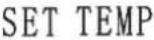 | Set temperature The symbol flashes during temperature setting | |
| [7D46] | Temperature | Air temperature display interval: 0-75 °CWater temperature display interval: 0-99 °C |
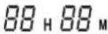 | Timer Displayed when the timer function is turned on | |
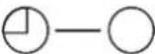 | Timer OFF | |
 | Timer ON | |
 | Night mode Always display in night mode | |
| [4807] | Timer for defrosting Displayed when timer-set defrosting is in progress | |
 | Compressor speed | Low Medium Hig |
Standby
When the heat pump is on, the control unit is in standby mode.
ON/OFF
Press the ON/OFF button to start the heat pump. The mode that was last used is activated. Press the ON/OFF button again to shut the heat pump off. After a power outage, the same settings that applied before the heat pump stopped are used. However, the timer is reset.
Select mode
Start the pump and press button (3) to select operating mode. You can choose between operating modes in the following order;

flowchart
graph LR
    A["Sun"] --> B["Snow"]
    B --> C["Steam"]
    C --> D["Return to Box"]
Heating mode should be used when energy saving measures are required. Hot water mode can be used if you rapidly need more hot water. In this mode, the heat pump can work as efficiently as possible and reach the set temperature in the shortest time possible.
TEMPERATURE SETTING
Press once on (15) or (16) to increase or decrease the temperature one degree at a time. Hold the buttons down if you wish to change the temperature at a faster rate.
The symbol for timer setting will flash on the display while the temperature is being adjusted. If no button is depressed within five seconds, the temperature setting will be saved and the display will return to its normal display.
Possible setting temperatures for heating: 25–52°C when regulating water temperature 16–31°C when regulating room temperature
Possible setting temperatures for cooling: 7-25°C when regulating water temperature 16-31°C when regulating room temperature
Temperature range for hot water mode: 25–52°C
AUTOMATIC AND Timer-SET dEFRoSTING
When the pump is run in heating or hot water mode, you can hold the AUX button (4) down for ten seconds to change between automatic (default) and timer-set defrosting. Timer-set defrosting is in progress when the "Timer for defrosting" symbol is displayed. In this mode, the heat pump is defrosted at regular intervals, provided that this is necessary. Hold the AUX button (4) down for ten seconds to change settings from timer-controlled to automatic defrosting. "Timer for defrosting" is no longer displayed since defrosting is now automatic. In this mode, the interval between defrostings is determined in an intelligent way based on previous requirements.
REGULATION of WATER/Room TEMPERATURE
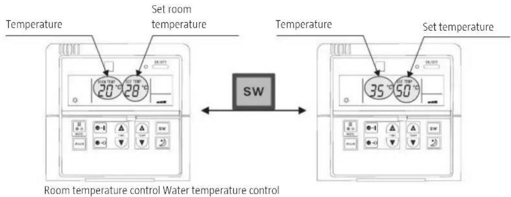
Keep in mind that the heat pump may not be able to supply hot water with a sufficiently high temperature when it is being run in room temperature mode. When the heat pump is run in heating or cooling mode, press "SW" to change between control based on water or *room temperature. The desired room temperature can be set when the "ROOM TEMP" text is displayed. The desired water temperature can be set when the "ROOM TEMP" text is not displayed.
NIGHT ModE
Night mode can only be used when the heat pump is run in heating mode and is regulated based on room temperature. When the heat pump is run in heating or cooling mode with a set room temperature, press button (9) to activate night mode. The "Night mode" symbol is displayed. Press button (9) again to cancel night mode. The "Night mode" symbol disappears. Night mode works as follows:
In heating mode: one hour after night mode is activated, the set temperature is lowered by two degrees. After another hour, the temperature is lowered by two additional degrees. The heat pump is now run at this temperature for another six hours after which night mode is cancelled. The heat pump automatically returns to the previous set room temperature.

line
| Time | Set Temperature | | ----------------- | --------------- | | 1 hour 2 hours 8 hours | T inst | | 2 hours | T inst-2 | | 8 hours | T inst-4 |In cooling mode: one hour after night mode is activated, the set temperature is increased by one degree. After another hour, the temperature is increased by one additional degree. The heat pump is now run at this temperature for another six hours after which night mode is cancelled. The heat pump automatically returns to the previous set room temperature.

line
| Time | Set Temperature | | ----------------- | --------------- | | 0 | T inst | | 1 hour 2 hours | T inst+2 | | 2 hours 8 hours | T inst+4 | | 8 hours | T inst+4 |TIMER ON/OFF
The timer can be set when the heat pump is in standby mode or when it is in operation. Use the following instructions:
Setting the timer in the ON position
- Press (11) to activate the power on timer. The (Timer ON) symbol is shown on the display.

- Set the start time in hours and minutes:
- Setting the timer: Hold the button (13) down to set the hours. The time advances one hour for each second you hold the button (13) depressed. Press repeatedly on (14) to turn back the time one hour at a time. The time is turned back one hour for each second you hold the button (14) depressed. Accepted time range: 0–23.

- Setting minutes: Press once on (13) to advance the minute setting. The time is advanced on minute each time you press (13). Press once on (14) to turn back the minute setting. The time is turned back one minute each time your press (14). Accepted minute range: 0–59.

- The timer setting is automatically saved when no button is pressed for five seconds. The countdown starts once the timer has been set. Once the set time has been reached, the heat pump starts and the timer setting is zeroed.
- The set time for the timer can even be controlled when the pump is shut off. Quickly press (11) twice to display set time.

Setting the timer in the OFF position
- Press (12) to activate the shut-off timer. The (Timer OFF) symbol is shown on the display.

- Set the shut-off timer in hours and minutes:
- Setting the timer: Hold the button (14) down to set the hours. The time advances one hour for each second you hold the button (14) depressed. Press repeatedly on (13) to turn back the time one hour at a time. The time is turned back one hour for each second you hold the button (13) depressed. Accepted time range: 0–23.
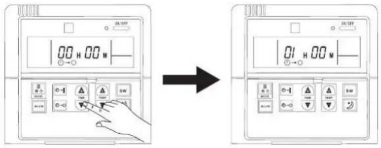
- Setting minutes: Press once on (14) to advance the minute setting. The time is advanced on minute each time you press (14). Press once on (13) to turn back the minute setting. The time is turned back one minute each time your press (13). Accepted minute range: 0–59.
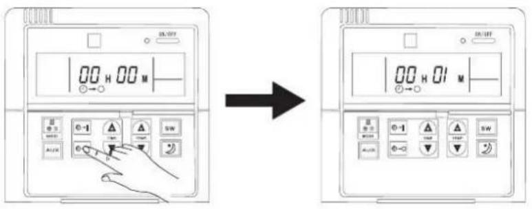
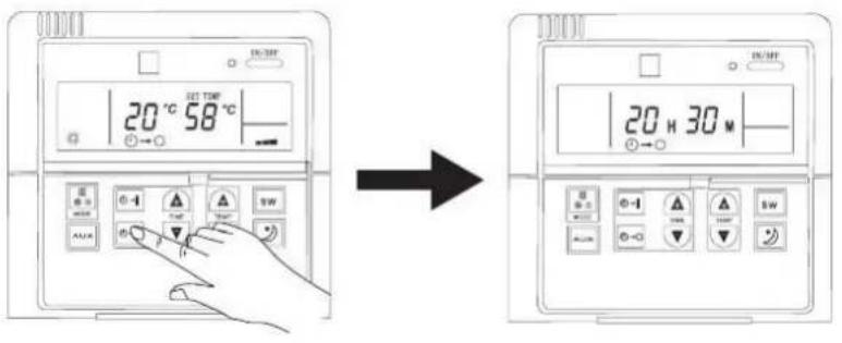
- The timer setting is automatically saved when no button is pressed for five seconds. Once you have set a stop time with the timer, the heat pump will run as usual until the timer expires. Once the stop time has been reached, the heat pump is shut off, regardless of current room temperature.
- In heating mode, hot water or cooling mode you can control which stop time has been set by quickly pressing (12) twice.
FROST PROTECTION
Level one:

When the heat pump is in standby mode and the ambient temperature falls below 5^ C, the code "P1" is displayed on the control panel.
When the heat pump is in standby mode and the ambient temperature exceeds 5^ C, the water pump stops and code "P1" disappears.
Level two:
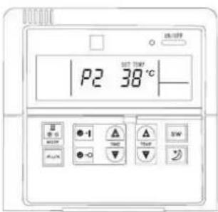
When the heat pump is in standby mode and the ambient temperature falls below 5^ C, and the water outlet temperature is below 3^ C, the heating of the heat pumps starts and code "P2" is displayed on the control panel.
When the heat pump is in standby mode and the ambient temperature exceeds 2^ C, and the water outlet temperature exceeds 8^ C, additional heat is shut off and code "P2" disappears.
ELECTRIC HEATER CARTRIDGE
The built-in electric heater cartridge can be used as a back-up heat source or for additional heat when the ambient temperature is too low or if the heat pump is not working effectively.
The electric heater cartridge starts when any one of these two conditions is satisfied:
A. The water temperature is lower than the setting for the electric heater cartridge's mechanical thermostat.
B. The heat pump's control unit assesses that its capacity is insufficient, and consequently starts the electric heater cartridge.
With respect to condition 1:
The electric heater cartridge is set to be turned on when the water temperature falls below 30^ as the capacity of the heat pump in this case is insufficient (can be due to extreme weather conditions or that he heat pump is not working).
It can also be set manually to a higher temperature if so desired. However, the thermostat of the electric heater cartridge must always be set to a temperature lower than that of the heat pump, otherwise the electric heater cartridge will be turned on before the heat pump starts working thereby rendering the entire system inefficient.
With respect to condition 2:
The heat pump's control unit will start the electric heater cartridge when ALL these conditions are satisfied:
• The ambient temperature is lower than 10^ C
• The compressor has run uninterrupted for 25 minutes
• The compressor is already working at maximum speed
• The water temperature is 3^ C lower than the set temperature
• The water temperature has increased less than 1^ C after 15 minutes
• The temperature has increased less than 1^ C after 15 minutes
The electric heater cartridge can also be set manually to increase the water temperature (60–75°C) for a limited time as a bactericidal measure.
Remember to return the temperature to its normal value when the bactericidal process has been completed!
TROUBLESHOOTING
| Part | Error code | Cause Control and remedy |
| The control panel | E0 | 1. A short-circuit or cable break has occurred in the cable between the control panel and the heat pump.2. The control panel is broken. |
| E1 | 1. The room temperature sensor in the control panel has short-circuited or become detached.2. Resistance problems in the room temperature sensor.3. The temperature sensors are not properly connected to the control panel. | |
| Systems | F1 Communication problems | |
| 1. Fault in temperature sensor at water inlet | ||
| Systems | F2 | 2. Fault in temperature sensor at water outlet | 1. Check if sensor cable has become disconnected. Attach it.2. A short-circuit or cable break has occurred in the cable between the control panel and the heat pump.3. Resistance problem in temperature sensor at water outlet. |
| 3. Fault in temperature sensor at coil in indoor unit | 1. Check if sensor cable has become disconnected. Attach it.2. A short-circuit or cable break has occurred in the cable between the control panel and the heat pump.3. Resistance problem in the room temperature sensor. | ||
| F3 Fault in current or voltage sensing. Replace printed circuit board in the outdoor unit. | |||
| F4 | Fault in compressor, fault in power module (PM), IPM protection | 1. Check if PFC sensor is loose. Attach it.2. Replace the PFC sensor3. Replace printed circuit board in the outdoor unit. | |
| F5 EEPROM fault in indoor unit | 1. Check if the EEPROM circuit is loose. Attach it.2. Replace the EEPROM unit in the indoor circuit | ||
| F6 | Excessively high coil temperature indoors in heating mode | 1. Check the water flow from the heat pump.2. Ambient temperature and water temperature are too high. Lower the set water temperature. | |
| Pipe temperature outside in cooling mode is too high | 1. Check the water flow from the heat pump.2. Ambient temperature and water temperature are too low Raise set water temperature. | ||
| Overcurrent protection | 1. Check the water flow from the heat pump.2. Ambient temperature and water temperature are too high/low. Raise or lower set water temperature. | ||
| F7 Voltage is too high/too low | 1. Check voltage at power supply.2. Replace printed circuit board in the outdoor unit. | ||
| F8* Faulty pressure switch | 1. Check pressure in the system.2. Replace pressure switch | ||
| F9 EEPROM fault in outdoor unit | 1. Check if the EEPROM circuit is loose. Attach it.2. Replace the EEPROM unit in the outdoor unit | ||
| Fb | Fault in the temperature sensor in outdoor unitFault in the temperature sensor in compressor outlet | 1. Check if sensor cable has become disconnected. Attach it.2. A short-circuit or cable break has occurred in the cable between the control panel and the heat pump.3. Resistance problem in temperature sensor. | |
| Fault in pipe temperature sensor in outdoor unit | |||
| Fault in the temperature sensor in compressor outlet | |||
| Fc | Safety function tripped due to too high/low pressure. | 1. Using a multimeter, measure at the pressure switch to investigate if the problem is a short-circuit of a missing connector. If so, replace it.2. Check the water flow to/from the heat pump. | |
| Fd | Safety function triggered due to ambient temperature | 1. Check the ambient temperature sensor.2. Check if the ambient temperature is too high/low. For cooling mode, the range is -1 to +65°C; for heating mode, the range is -25 to +45°C | |
| Systems | Fe Not used. | ||
| FF Faulty indoor water pump or flow switch. | 1. Check the water pump's flow rate.2. Check the connection to the flow switch. Check whether the water flow in the system is sufficient and whether the flow switch is closed or not. If not, replace the flow switch. | ||
* The difference between F8 and Fc:
System pressure protection
When the compressor is running and the system pressure becomes too great, the pressure switch switches off (the pressure switch is normally on during normal operation). The control unit then lowers the compressor's work rate by 1 Hz per second until the pressure switch is switched on again. At the same time, the current speed of the compressor is recorded, and this speed minus 1 Hz is then used as the maximum speed. This limit value is automatically set to zero after the compressor has been run normally for two hours. However, if the protection is triggered again before two hours have elapsed, the control unit will use the new operating frequency, lower it by another 1 Hz, and then use it as the maximum speed. The same applies here: the limit value is reset when the compressor has run normally for two hours. If the compressor is shut off and the control unit does not have contact with the pressure switch for five seconds, it will interpret this as the pressure switch being broken, and an applicable code will be displayed on the control panel.
In order to determine if the pressure switch is broken or if it is a different problem, do as follows:
- 1 Shut the heat pump off and disconnect the power supply. Wait for ten minutes.
- Start the heat pump.
- If error code F8 is displayed as soon as the pump is started, then there is a fault with the pressure switch, or it has a loose cable.
- If no error code is displayed, the secondary refrigerant system is not working as it should causing the pressure limit protection to trip.
The following factors can cause excessive pressure in the system:
• Water flow too weak.
- Blocked water filter
- Too much refrigerant
• Water temperature too high
- Pipe bends too sharply
- Error in EEV
Jula reserves the right to make changes. In the event of problems, please contact our service department. www.jula.com

Care for the environment!
Must not be discarded with household waste!
This product contains electrical or electronic
components that should be recycled.
Leave the product for recycling at the designated
station e.g. the clocal authority's recycling station.
Installaon check and start-up report
When the installation is ready it should be checked before the system is started. A copy of the report should be sent to Julia.
Technician:
Address:
Postcode:.... Place:....
| Model: | Serial no. indoor unit | Serial no. outdoor unit |
| Tank: | Type of additional heat: | Set temperature of additional heat: |
Informaon on installaon:
| Pipe dimensions | |
| Dimensions of Iters & ball valves | |
| Has the heang system been cleaned | |
| Separate current and ampere | |
| Speed of circulaon pump - distrubuon | |
| Leakage test of water circuit | |
| Leakage test of refrigerant circuit | |
| Refrigerant pipes ghtened with Nm: |
Simple diagram of ow chart:
The water temperature in the system should not be less than 25^ C. Carry out the measurements below aer 15 minutes in operaon. The set temperature should be 52^ C and the compressor should be in stage 3.
| Seng of circulaon pump | |
| Outdoor temperature | |
| Temperature of heat pump – display | |
| Temperature of hot gas pipe – large pipe | |
| Temperature of return pipe – small pipe | |
| Temperature of water in heat pump | |
| Temperature of water in heat pump | |
| Voltage and power consumpon ( V & A ) |
Aer the measurements have been taken and the
system is working sasfactorily, set the heat pump to the required temperature and reghten the couplings.
Date:..... Technician.....
A copy of the documents sent by e-mail kundservice@jula.se or Julia AB, Box 363, 532 24 Skara, Sweden.
- SVENSKA....4
- SÄKERHETSANVISNINGAR....4
- TEKNISK dATA 5
- BESKRIVNING 6
- Inomhusenhet 6
- Utomhusenhet....7
- MoNTERING 8
- SAFETY INSTRUCTIONS....76
- TECHNICAL DATA 77
- dESCRIPITIoN 78
- Indoor unit 78
- Outdoor unit....79
- INSTALLATION 80
- Installation of Indoor Unit 82
- Installing the outdoor unit 83
- The control panel....89
- Electric heater cartridge 95
- Troubleshooting....96
- SÄKERHETSANVISNINGAR
- INSTALLERA UTOMHUSENHETEN
- Håltagning
- VIKTIGT!
- Ställa in timer AV
- FROSTSKYDD
- Nivå ett:
- UTEDEL
- INSTALLER UTEND∅RSENHETEN
- Hulltaking
- VIKTIG!
- Stille inn timeren AV
- FROSTBESKYTTELSE
- Nivå en:
- Wykonywanie otworów
- WAŻNE!
- Read the User Instructions carefully before use
- TEcHNl cAL dATA
- dEScRIPTIoN
- INdooR UNIT
- OUTDOOR UNIT
- INSTALLATION
- Area of application 1
- Area of application 2
- INSTALLATION OF INDOOR UNIT
- Installation notes
- TIP:
- INSTALLING THE OUTDOOR UNIT
- Installation on the ground
- Wall installation
- cable installation
- Power cable between the indoor and outdoor unit
- Installation kit
- Hole-making
- Piping and wiring
- Pull the secondary refrigerant
- IMPORTANT!
- Mounting the installation kit
- Connecting the water pipes
- Installing the control panel
- Check before initial start
- Checks before starting
- THE coNTRoL PANEL
- Standby
- ON/OFF
- Select mode
- TEMPERATURE SETTING
- AUTOMATIC AND Timer-SET dEFRoSTING
- REGULATION of WATER/Room TEMPERATURE
- NIGHT ModE
- TIMER ON/OFF
- Setting the timer in the ON position
- Setting the timer in the OFF position
- FROST PROTECTION
- Level one:
- Level two:
- ELECTRIC HEATER CARTRIDGE
- With respect to condition 1:
- With respect to condition 2:
- System pressure protection
- Care for the environment!
- Installaon check and start-up report
Brand : Anslut
Model : 416-116
Category : Air Conditioning