417-030 - Air Conditioning Anslut - Free user manual and instructions
Find the device manual for free 417-030 Anslut in PDF.


| Product Type | Portable Air Conditioner |
| Brand | Anslut |
| Model | 417-030 |
| Power Supply | 220-240 V ~ 50 Hz |
| Cooling Capacity | 9000 BTU (2.6 kW) |
| Air Flow Rate | 300 m³/h (high speed) |
| Noise Level | ≤ 55 dB(A) |
| Refrigerant Type | R32 |
| Dimensions (W x H x D) | 330 x 700 x 350 mm |
| Weight | 25 kg |
| Functions | Cooling, Fan, Dehumidification |
| Timer | 24-hour programmable timer |
| Remote Control | Included (battery type AAA x2) |
| Filter Type | Washable mesh filter |
| Energy Efficiency | EER: 2.6 (class A) |
| Maintenance | Clean filter every 2 weeks; drain condensate regularly |
| Safety Features | Overheat protection, anti-freeze protection, auto restart |
| Spare Parts Available | Filter, remote control, exhaust hose, window kit |
| Documentation | User manual in multiple languages (EN, NO, PL, SV) |
Frequently Asked Questions - 417-030 Anslut
User questions about 417-030 Anslut
0 question about this device. Answer the ones you know or ask your own.
Ask a new question about this device
Download the instructions for your Air Conditioning in PDF format for free! Find your manual 417-030 - Anslut and take your electronic device back in hand. On this page are published all the documents necessary for the use of your device. 417-030 by Anslut.
USER MANUAL 417-030 Anslut
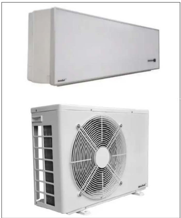
Operating Instructions for Heat Pump Air/Air
417-030
natural_image
Two white industrial air conditioning units with fan blades, shown from different angles (no text or symbols visible)SV Bruksanvisning i original
NO Bruksanvisning i original
EN Operating instructions in original
SVENSKA 7
GARANTIVILLKOR 7
Generella villkor 7
Garantivillkor 7
Övriga villkor 7
GENERELL INFORMATION 8
DRIFTSINNSTILLING 41
Autodrift 41
Kjøling 41
Luftavfukting....41
Luftsirkulasjon 41
Varme....42
Viftehastighet 42
General conditions....93
Guarantee terms and conditions....93
Other conditions....93
GENERAL INFORMATION 94
Important before installation 94
Important information....94
DESCRIPTION 95
Indoor unit 95
Outdoor unit 95
REMOTE CONTROL 96
Using the remote control....96
Replacing the battery in the remote control 96
If the remote control does not work 97
USE 97
DISPLAY 97
OPERATING MODES 98
Auto mode....98
Cooling 98
Dehumidification 98
Air circulation 98
Heating....99
Fan speed 99
Controlling the damper....100
Night-reduction....100
MAINTENANCE 100
After every heating season 100
Before every heating season....100
Important....101
Filters and cleaning....101
Miscellaneous 102
USER TIPS....102
Cooling....102
Heating....102
Energy-saving economy 102
Roof over outdoor unit 103
WIRING DIAGRAM 103
INDOOR UNIT 103
OUTDOOR UNIT....104
INSTALLATION 104
Check list 104
Pay attention to the following....105
Module system....105
Positioning the outdoor unit 105
Tools 105
Indoor unit 106
Outdoor unit 106
Installation kit 107
Positioning of indoor unit 107
Fitting the wall bracket for the indoor unit 107
Hole-making....108
Mounting the indoor unit 108
Wall inlet 109
Positioning of the outdoor unit 110
Outdoor unit brackets.... 110
Mounting the outdoor unit 110
Installing the refrigerant pipes.... 111
Pipe routing....112
Drainage hose....112
Connecting the installation kit.... 112
Electrical connection - indoors....113
Electrical connection – outdoor unit.... 113
Error codes 113
Safety 114
TECHNICAL DATA....114
SERVICE BOOKLET 115
natural_image
Illustration showing a hand inserting a component into a device, with no text or symbols present.HANDHAVANDE
natural_image
Diagram of a vehicle air vent with directional arrows indicating flow or movement (no text or symbols)natural_image
Illustration of a hand using a tool to clean or store floor tiles (no text or symbols present)
natural_image
Line drawing of a hand washing clothes from a sink with a faucet (no text or symbols)natural_image
Illustration of a person cleaning a large cylindrical object with sparkles (no text or symbols)natural_image
Simple line drawing of a person looking up at a window with horizontal bars (no text or symbols)Uppvärmning
natural_image
Illustration of a person reaching toward a window with a magnifying glass (no text or symbols)Energiekonomi
natural_image
Illustration of two cartoon-style car windows with expressive faces, one showing a broken door and the other holding a rolled document (no text or symbols present)natural_image
Simple line drawing of a smiling refrigerator with a sun and cloud, no text or symbols presentKOPPLINGSSCHEMA
INNEDEL

flowchart
graph TD
    A["TO OUTDOOR UNIT"] --> B["SINGNAL CONNECTOR"]
    A --> C["POWER CONNECTOR"]
    A --> D["ELECTRIC CASE"]
    D --> E["INREADABLE"]
    D --> F["AC-N"]
    F --> G["AC-L"]
    G --> H["FAN MOTOR FM 1~"]
    H --> I["FAN1"]
    H --> J["CON1"]
    H --> K["CN1"]
    H --> L["RT PT"]
    H --> M["SW"]
    M --> N["CN-SMD"]
    M --> O["SM"]
    O --> P["COIL SENSOR"]
    O --> Q["ROOM TEMP SENSOR"]
    O --> R["STEPM MOTOR"]
    R --> S["DISPLAY BOARD"]
    R --> T["TO OUTDOOR UNIT"]
    U["INDOOR UNIT CONTROL"] --> V["POWER PLUG YLW/GRN"]
    W["TRANSFORMER"] --> X["TAKEOVER BOARD"]
    Y["CN-DISP"] --> Z["CN-RCY"]
    style A fill:#f9f,stroke:#333
    style U fill:#ccf,stroke:#333
    style W fill:#cfc,stroke:#333
    style Y fill:#fcc,stroke:#333
UTEDEL

flowchart
graph TD
    A["HEAT PUMP OUTDOOR WIRING DIAGRAM"] --> B["GZ"]
    B --> C["CM 1~"]
    C --> D["C1"]
    D --> E["R"]
    E --> F["S"]
    F --> G["C2"]
    G --> H["FM 1~"]
    H --> I["YLW/GRN"]
    I --> J["POWER CONNECTOR"]
    J --> K["N.O. COM"]
    K --> L["CY-OUT"]
    L --> M["ORT OPT"]
    M --> N["OUTDOOR PCB"]
    N --> O["OUTDOOR TEMP SENSOR"]
    N --> P["OUTDOOR COLL SENSOR"]
    Q["CONDENSER HEATER"] --> R["CRANKCASE HEATER"]
    R --> S["VALVE"]
    S --> T["AC-N1"]
    T --> U["AC-N2"]
    U --> V["OF-AN"]
    V --> W["4WAY"]
    W --> X["QZHT"]
    X --> Y["LNHT"]
    Z["SINGNAL CONNECTOR"] --> AA["CONNECTOR"]
    AA --> AB["OUTDOOR TEMP SENSOR"]
    AA --> AC["OUTDOOR COLL SENSOR"]
    AD["TO INDOOR UNIT"] --> AE["YLW/GRN"]
MONTERING
Checklista
natural_image
Assorted electrical tools and components laid out on grass, including a red drill, power tool, pliers, and tools (no visible text or labels)Inomhusdel
natural_image
Technical line drawing of an air conditioner unit with coiled tubing (no text or symbols)
natural_image
Simple line drawing of a mechanical device with a handle and lever (no text or symbols)Utomhusdel
natural_image
Close-up of a mechanical device with two protruding components, no visible text or symbols
natural_image
Exterior view of a modern office building (no signage)Monteringskit
natural_image
Assorted electrical components including coiled wires, batteries, and tubing (no visible text or symbols)

natural_image
Pure technical diagram of a mechanical assembly without any text, numbers, or symbols150
250
VIKTIGT!
natural_image
Person using a red power drill on a wooden cabinet (no visible text or symbols)
natural_image
Close-up of hands using a red drill bit to clean electrical outlets (no visible text or symbols)natural_image
Close-up of hands installing a black and white hose component on a wooden surface (no text or symbols visible)Utomhusdelens placering
natural_image
Man using a tool to adjust or install a wall-mounted device (no visible text or symbols)natural_image
Two-panel photo showing hands installing or adjusting a wall-mounted device, no visible text or symbolsnatural_image
Close-up of hands adjusting a pipe fitting with white insulation and brass fittings (no visible text or symbols)natural_image
Pure geometric diagram showing concentric curved lines and a circle with crosshairs (no text or symbols)natural_image
Close-up of a hand inserting wires into an electrical switchgear box (no visible text or symbols)
natural_image
Close-up of a hand using a tool to adjust or install a mechanical component, with no visible text or symbols.natural_image
Close-up of hands operating a mechanical device with copper fittings and yellow components (no visible text or symbols)natural_image
Interior view of an electrical enclosure showing wiring and a black connector (no visible text or symbols)natural_image
Illustration of a hand inserting a component into a device, showing the process (no text or symbols present)DRIFT
natural_image
Diagram of a mechanical component with arrows indicating upward motion (no text or symbols)natural_image
Illustration of a hand using a tool to clean or store floor tiles (no text or symbols present)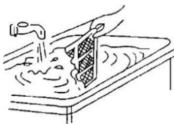
natural_image
Line drawing of a hand washing a sink with a pipe, no text or symbols presentnatural_image
Illustration of a person cleaning a cylindrical object with sparkles (no text or symbols)natural_image
Simple line drawing of a person looking up at a window with horizontal bars (no text or symbols)Oppvarming
natural_image
Illustration of a person waving near a window (no text or symbols)Energiøkonomi
natural_image
Illustration of two cartoon-style objects: a card with a smiling face and a rolled document or eraser (no text or symbols)Tak til utedelen
natural_image
Simple line drawing of a smiling refrigerator with sun and cloud, no text or symbols presentKOBLINGSSKJEMA
INNEDEL

flowchart
graph TD
    A["POWER PLUG"] --> B["EXPIRUCTOR SWITCH"]
    B --> C["AC-N"]
    C --> D["FAN MOTOR FM 1~"]
    D --> E["FAN1"]
    E --> F["CON1"]
    F --> G["CN1"]
    G --> H["RT PT"]
    H --> I["SW"]
    I --> J["CN-SMD"]
    J --> K["SM STEP MOTOR"]
    K --> L["DISPLAY BOARD"]
    L --> M["TO OUTDOOR UNIT"]
    M --> N["SINGNAL CONNECTOR POWER CONNECTOR"]
    N --> O["SINGNAL CONNECTOR"]
    O --> P["FAN MOTOR FM 1~"]
    P --> Q["FAN1"]
    Q --> R["CON1"]
    R --> S["CN1"]
    S --> T["RT PT"]
    T --> U["SW"]
    U --> V["CN-SMD"]
    V --> W["SM STEP MOTOR"]
    W --> X["DISPLAY BOARD"]
    X --> Y["TAKEOVER BOARD"]
UTEDEL

MONTERING
Sjekkliste
natural_image
Assorted electrical tools and components laid out on grass, including a red drill, pliers, and tools (no visible text or labels)Innedel
natural_image
Technical line drawing of an air conditioner internal structure with coiled tubing (no text or symbols)
natural_image
Simple line drawing of a mechanical lever or lever assembly (no text or symbols)Utedel
natural_image
Close-up of a mechanical device with two protruding components and a yellow warning label (no readable text or symbols)
natural_image
Exterior view of a modern office building (no signage)Monteringssett
natural_image
Assorted electrical cable and tubing components including coiled wires, batteries, and connectors (no visible text or symbols)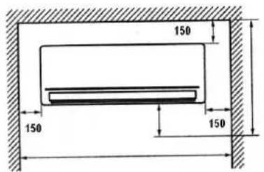

VIKTIGT!
Monter alltid innedelen horisontalt.
natural_image
Person using a red power tool against a plain wall (no text or symbols visible)
natural_image
Person using a red electric drill putter on a wall socket (no visible text or symbols)natural_image
Pure mechanical joint diagram without any text, numbers, or symbols
natural_image
Close-up of hands installing a white and gray flexible hose on a dark metal wall (no text or symbols visible)natural_image
Man working on a wall-mounted device with tools, no visible text or symbols
Montering av utedel
natural_image
Two-panel photo showing hands interacting with a wall-mounted device; no visible text or symbols.natural_image
Close-up of hands holding a golden pipe fitting (no visible text or symbols)
natural_image
Close-up of hands adjusting a metal pipe fitting with a brass sleeve (no visible text or symbols)natural_image
Close-up of a hand adjusting a mechanical component with three circular components (no visible text or symbols)
natural_image
Close-up of hands installing or adjusting a mechanical component on a white electronic device (no visible text or symbols)natural_image
Close-up of hands installing or adjusting a brown electrical component on an open electrical panel (no visible text or symbols)Elektrisk tilkobling innedel
VIKTIG!
natural_image
Interior view of an electrical enclosure showing wiring and components (no visible text or symbols)The Ground Truth image displays a single, solid horizontal line, which is a stylistic or background element (like a ruled paper line or separator), not a placeholder for text. According to Rule 2, such stylistic/background lines must be ignored by the OCR result. The OCR content provided is "", which consists of no characters. This correctly represents the absence of any textual content in the GT and correctly ignores it as a hallucination. Therefore, the OCR output should have been empty or contained no text. Hence, the OCR result is consistent with the Ground Truth.
Overtrykk:

bar

bar
Sugetrykk:

The Ground Truth image displays a single, solid horizontal line. According to Rule 2 (UNDERSCORE & LINE RULES), if the GT contains lines used for stylistic emphasis or as background (like ruled paper), the OCR result must ignore them. The provided OCR content is "____", which consists of four underscores. This is incorrect because underscores are not equivalent to a solid line and are not permitted under the “Stylistic/Background Lines (Ignore)” rule. Outputting underscores for a stylistic line violates the rule and constitutes an error. Therefore, the OCR result is inconsistent with the Ground Truth.
Overtrykk:

bar

bar
Sugetrykk:
Etterfylling:

The Ground Truth image displays a single, solid horizontal line. According to Rule 2 (UNDERSCORE & LINE RULES), if the GT contains lines used for stylistic emphasis or as background (like ruled paper), the OCR result must ignore them. The provided OCR content is "____", which consists of four underscores. This is incorrect because underscores are not equivalent to a solid line and are not permitted under the “Stylistic/Background Lines (Ignore)” rule. Outputting underscores for a stylistic line violates the rule and constitutes an error. Therefore, the OCR result is inconsistent with the Ground Truth.
Overtrykk:

bar
Sugetrykk:

bar
Etterfylling:

The Ground Truth image displays a single, solid horizontal line, which is a stylistic or background element (like a ruled paper line or separator), not a placeholder for text. According to Rule 2, such stylistic/background lines must be ignored by the OCR result. The OCR content provided is "", which consists of no characters. This correctly represents the absence of any textual content in the GT and correctly ignores it as a fill-in-the-blank placeholder. Since the GT contains no actual underscores and the OCR outputted nothing for this line, this complies with the “Stylistic/Background Lines (Ignore)” rule. Therefore, the OCR result is consistent with the Ground Truth.
Overtrykk:

bar
Sugetrykk:

bar
Etterfylling:

The Ground Truth image displays a single, solid horizontal line. According to Rule 2 (UNDERSCORE & LINE RULES), if the GT contains lines used for stylistic emphasis or as background (like ruled paper), the OCR result must ignore them. The provided OCR content is "____", which consists of four underscores. This is incorrect because underscores are not equivalent to a solid line and are not permitted under the “Stylistic/Background Lines (Ignore)” rule. Outputting underscores for a stylistic line violates the rule and constitutes an error. Therefore, the OCR result is inconsistent with the Ground Truth.
Overtrykk:

bar

bar
Sugetrykk:

The Ground Truth image displays a single, solid horizontal line. According to Rule 2 (UNDERSCORE & LINE RULES), if the GT contains lines used for stylistic emphasis or as background (like ruled paper), the OCR result must ignore them. The provided OCR content is "____", which consists of four underscores. This is incorrect because underscores are not equivalent to a solid line and are not permitted under the “Stylistic/Background Lines (Ignore)” rule. Outputting underscores for a stylistic line violates the rule and constitutes an error. Therefore, the OCR result is inconsistent with the Ground Truth.
Overtrykk:

bar
Sugetrykk:

bar
Etterfylling:

natural_image
Illustration showing a hand inserting a cylindrical component into a machine, with no text or symbols present.OBSŁUGA
natural_image
Diagram of a vehicle or container with arrows indicating upward movement (no text or symbols)natural_image
Illustration of a hand using a tool to clean or install a small object, with no visible text or symbols.
natural_image
Line drawing of hands washing a basin with a faucet, no text or symbols presentnatural_image
Illustration of a person cleaning a large cylindrical object with sparkles (no text or symbols)natural_image
Illustration of a person climbing a window with horizontal bars (no text or symbols)Ogrzewanie
natural_image
Illustration of a person reaching toward a window with a glass behind them (no text or symbols)Oszczędność energii
natural_image
Illustration of two cartoon-style boxes, one with a broken lid and the other with a rolled document (no text or symbols)natural_image
Simple line drawing of a smiling refrigerator with sun and cloud, no text or symbols presentSCHEMAT POŁĄCZEŃ
CZEŚĆ WEWNETRZNA

flowchart
graph TD
    A["GO DO CZĘŚCI"] --> B["ZŁĄCZE SYGNAŁOWE"]
    A --> C["ZŁĄCZE ZASILANIA"]
    A --> D["SKRZYNKA ELEKTRYCZNA"]
    A --> E["N L"]
    A --> F["AC-N"]
    A --> G["AC-L"]
    H["TECHNOŚKI"] --> I["SILNIK WENTYLA TORA FM 1-"]
    I --> J["WENTYLATOR 1"]
    I --> K["CONI"]
    I --> L["CNI"]
    I --> M["RT PT"]
    N["KONTOLER CZĘŚCI WEWNETRZNEJ"] --> O["TRANSFORMATOR"]
    P["CTUJNIK TEMPERATURY POKOJOWEJ"] --> Q["CZUJNIK CEWKI"]
    R["CTUJNIK TEMPERATURY POKOJOWEJ"] --> S["CZUJNIK CEWKI"]
    T["CTUJNIK TEMPERATURY POKOJOWEJ"] --> U["CZUJNIK CEWKI"]
    V["CTUJNIK TEMPERATURY POKOJOWEJ"] --> W["CZUJNIK CEWKI"]
    X["CTUJNIK TEMPERATURY POKOJOWEJ"] --> Y["CZUJNIK CEWKI"]
    Z["CTUJNIK TEMPERATURY POKOJOWEJ"] --> AA["CZUJNIK CEWKI"]
    AB["CTUJNIK TEMPERATURY POKOJOWEJ"] --> AC["CZUJNIK CEWKI"]
    AD["CTUJNIK TEMPERATURY POKOJOWEJ"] --> AE["CZUJNIK CEWKI"]
    AF["CTUJNIK TEMPERATURY POKOJOWEJ"] --> AG["CZUJNIK CEWKI"]
    AH["CTUJNIK TEMPERATURY POKOJOWEJ"] --> AI["CZUJNIK CEWKI"]
    AJ["CTUJNIK TEMPERATURY POKOJOWEJ"] --> AK["CZUJNIK CEWKI"]
    AL["CTUJNIK TEMPERATURY POKOJOWEJ"] --> AM["CZUJNIK CEWKI"]
    AN["CTUJNIK TEMPERATURY POKOJOWEJ"] --> AO["CZUJNIK CEWKI"]
    AP["CTUJNIK TEMPERATURY POKOJOWEJ"] --> AQ["CZUJNIK CEWKI"]
    AR["CTUJNIK TEMPERATURY POKOJOWEJ"] --> AS["CZUJNIK CEWKI"]
    AT["CTUJNIK TEMPERATURY POKOJOWEJ"] --> AU["CZUJNIK CEWKI"]
    AV["CTUJNIK TEMPERATURY POKOJOWEJ"] --> AW["CZUJNIK CEWKI"]
    AX["CTUJNIK TEMPERATURY POKOJOWEJ"] --> AY["CZUJNIK CEWKI"]
    AZ["CTUJNIK TEMPERATURY POKOJOWEJ"] --> BA["CZUJNIK CEWKI"]
    BB["CTUJNIK TEMPERATURY POKOJOWEJ"] --> BC["CZUJNIK CEWKI"]
    BD["CTUJNIK TEMPERATURY POKOJOWEJ"] --> BE["CZUJNIK CEWKI"]
    BF["CTUJNIK TEMPERATURY POKOJOWEJ"] --> BG["CZUJNIK CEWKI"]
    BH["CTUJNIK TEMPERATURY POKOJOWEJ"] --> BI["CZUJNIK CEWKI"]
    BJ["CTUJNIK TEMPERATURY POKOJOWEJ"] --> BK["CZUJNIK CEWKI"]
    BL["CTUJNIK TEMPERATURY POKOJOWEJ"] --> BM["CZUJNIK CEWKI"]
    BN["CTUJNIK TEMPERATURY POKOJOWEJ"] --> BO["CZUJNIK CEWKI"]
    BP["CTUJNIK TEMPERATURY POKOJOWEJ"] --> BQ["CZUJNIK CEWKI"]
    BR["CTUJNIK TEMPERATURY POKOJOWEJ"] --> BS["CZUJNIK CEWKI"]
    BT["CTUJNIK TEMPERATURY POKOJOWEJ"] --> BU["CZUJNIK CEWKI"]
    BV["CTUJNIK TEMPERATURY POKOJOWEJ"] --> BW["CZUJNIK CEWKI"]
    BX["CTUJNIK TEMPERATURY POKOJOWEJ"] --> BYC["CZUJNIK CEWKI"]
    BQ --> BQ
    BQ --> BQ
    BQ --> BQ
    BQ --> BQ
    BQ --> BQ
    BQ --> BQ
    BQ --> BQ
    BQ --> BQ
    BQ --> BQ
    BQ --> BQ
    BQ --> BQ
    BQ --> BQ
    BQ --> BQ
    BQ --> BQ
    BQ --> BQ
    style A fill:#f9f,stroke:#333
    style B fill:#ccf,stroke:#333
    style C fill:#cfc,stroke:#333
    style D fill:#fcc,stroke:#333
    style E fill:#cff,stroke:#333
    style F fill:#ffc,stroke:#333
    style G fill:#cfc,stroke:#333
    style H fill:#cfc,stroke:#333
    style I fill:#cfc,stroke:#333
    style J fill:#cfc,stroke:#333
    style K fill:#cfc,stroke:#333
    style L fill:#cfc,stroke:#333
    style M fill:#cfc,stroke:#333
    style N fill:#cfc,stroke:#333
    style O fill:#cfc,stroke:#333
    style P fill:#cfc,stroke:#333
    style Q fill:#cfc,stroke:#333
    style R fill:#cfc,stroke:#333
    style S fill:#cfc,stroke:#333
    style T fill:#cfc,stroke:#333
    style U fill:#cfc,stroke:#333
    style V fill:#cfc,stroke:#333
    style W fill:#cfc,stroke:#333
    style X fill:#cfc,stroke:#333
    style Y fill:#cfc,stroke:#333
    style Z fill:#cfc,stroke:#333
CZEŚĆ ZEWNETRZNA

flowchart
graph TD
    A["CIEPŁA"] --> B["CM 1~"]
    B --> C["FM 1~"]
    C --> D["ZÓŁTY/ZIELONY"]
    D --> E["GRZEJNIK KONDENSACYJNY"]
    E --> F["PODGRZEWACZ SKRZYNI KORBOWEJ"]
    F --> G["ZAWÓR"]
    G --> H["CY-OUT"]
    H --> I["ORT OPT"]
    I --> J["ZEWNETRZNA PŁYTKA DRUKOWANA"]
    J --> K["ZEWNETRZNEJ"]
    K --> L["DO CZĘŚCI WEWNĘTRZNEJ"]
    M["AZ07083A"] --> N["*ZABEZPIECZENIE PRZECIAŻENIOWE"]
    N --> O["C1"]
    O --> P["R"]
    P --> Q["S"]
    Q --> R["C2"]
    R --> S["+"]
    S --> T["GRZEJNIK KONDENSACYJNY"]
    T --> U["PODGRZEWACZ SKRZYNI KORBOWEJ"]
    U --> V["ZAWÓR"]
    V --> W["CY-OUT"]
    W --> X["ORT OPT"]
    X --> Y["ZEWNETRZNA PŁYTKA DRUKOWANA"]
    Y --> Z["UWAGA:GZ' OZNACZA KOMPRESORY Z ZEWNETRZNYM ZABEZPIECZENIEM PRZECIAŻENIOWYM"]
MONTAŻ
Lista kontrolna
natural_image
Assorted tools and equipment laid out on grass, including a red power drill, pliers, and tools (no visible text or symbols)Część wewnętrzna
natural_image
Technical line drawing of an internal air conditioner housing with coiled cable (no text or symbols)
natural_image
Simple line drawing of a mechanical lever or lever assembly (no text or symbols)Część zewnętrzna
natural_image
Close-up of a mechanical device with a lever and mounting bracket (no visible text or symbols)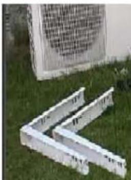
natural_image
Exterior view of a modern office building (no signage)Zestaw montażowy
natural_image
Assorted automotive air ducts and components laid out on a white background (no text or symbols visible)
WAŻNE!
natural_image
Person using a red power tool against a plain wall (no text or symbols visible)
natural_image
Person using a red drill bit on a wall socket (no visible text or symbols)natural_image
Pure technical line drawing of a mechanical joint or bracket (no text or symbols)
natural_image
Close-up of hands installing a black rubber hose with a white plastic ring on a dark metal wall (no text or symbols visible)natural_image
Man working on a wall-mounted device with tools, no visible text or symbols
natural_image
Two-panel image showing hands interacting with a wall panel and a device, no visible text or symbolsnatural_image
Close-up of hands adjusting a pipe fitting with a brass valve (no visible text or symbols)natural_image
Pure geometric diagram showing concentric curved lines and a circle with crosshairs (no text or symbols)natural_image
Hand inserting a small mechanical component into an electrical device (no visible text or symbols)
natural_image
Close-up of a hand using a tool to adjust or install a mechanical component, no visible text or symbolsnatural_image
Close-up of hands installing or adjusting a brown electrical component on an open electrical panel (no visible text or symbols)natural_image
Interior view of an electrical enclosure showing wiring and components (no visible text or symbols)Read the Operating Instructions carefully before use!
GUARANTEE TERMS AND CONDITIONS
General conditions
Dear Customer,
We would like to congratulate you on your choice of an Anslut air/air heat pump. The heat pump will reduce your heating costs and create a healthy and comfortable indoor environment all year round. The heat pump is built using the latest available technology for optimum performance, durability and comfort. The patented installation system allows for savings in the installation of the product.
Guarantee terms and conditions
The patented quick release system means the air/air heat pump is very easy to install without any special tools. Must be installed by a professional!
According to the Consumer Purchase Act this product carries a 3 year guarantee against manufacturing defects when purchased by a private person. We give a 5 year compressor guarantee and a 2 year guarantee on other parts. If you are making a claim for compensation under the guarantee, you must be able to produce proof of purchase, completed service documentation and proof to show that the product has been installed and used according to the information in the operating and installation instructions. If, because of the type of fault, location, access, and time factor, Julia considers repairs on site to be impractical, you may be obliged to take the product to the nearest Julia store in the event of a claim.
When operated commercially, a 1 year guarantee against manufacturing defects and a 5 year compressor guarantee are given. The owner of the business is responsible for ensuring compliance with legal and regulatory requirements.
It is essential to read all the operating and installation instructions before starting installation. Follow the instructions carefully, step by step. It is equally important that you read these operating instructions before putting the system into operation. This is our guarantee in order for you to have confidence in the product. We want you to be a satisfied user of your Anslut heat pump.
Service and service intervals:
Service must be carried out regularly at least every other year. The first service must be carried out within one year of installation and the start of the system. Note that the guarantees become void if service has not been carried out.
Other conditions
Faults constitute, according to a Julia approved professional assessment, departure from the normal standard. Faults or defects resulting from abnormal use, both mechanical and environmental, are not covered by this guarantee.
Neither is Julia liable for any faults due to failure to follow the installation and/or maintenance instructions. Upon receipt of this product, it should be carefully examined. If faults are detected, they must be reported before using the product. In general faults must be reported immediately.
Jula cannot be held responsible for any indirect damage, i.e. damage to property other than the product, personal injury, loss of property, loss of business, or loss resulting from downtime etc. Jula's responsibility does not cover compensation for any increased energy consumption caused by product or installation faults.
In the event of a claim it is necessary to submit confirmation in writing that an authorised technician has carried out the installation.
Guarantee claims, including ordering of service documents, are to be made to Julia AB on telephone +46 (0)200 885588. Do not carry out any repairs on your own initiative, otherwise this will invalidate the guarantee.
GENERAL INFORMATION
Important before installation
• Refrigerant pipes with a radius of less than 15 cm must NOT be bent.
- Never connect the power before the pipes have been routed and the system modules are connected.
- The units are heavy and aluminium chips/sharp edges can cause cuts on the hands. Bend your knees when lifting, and wear gloves and safety glasses during installation.
- Read through all the operating and assembly instructions before commencing the installation.
• The plastic plugs on the ends of the pipe must not be removed until the pipes are to be connected.
- Retighten couplings after 24 h. Tightening torque for refrigerant couplings min. 18 Nm. Use a torque wrench when in doubt. Make sure you have been supplied with an indoor unit and outdoor unit with the same model designation.
ELECTRICAL SAFETY
New installations and extensions to existing systems must always be performed by a qualified electrician. If you have the necessary experience and knowledge, you may replace switches and wall sockets, fit plugs, extension cords and lamp holders. If not, you should contact an electrician. Improper installation may result in electric shock or fire.
Important information
- The heat pump uses environmentally-friendly R410A refrigerant, which has one of the highest energy efficiency values in the industry. The unit is inverter controlled, which means that the compressor has a variable speed to ensure better efficiency.
- The energy the inverter delivers is monitored at all times by the system and is adapted in line with external, internal and ambient factors to be as energy efficient as possible. This also means that the amount of energy inside the system is regulated constantly, which means the best possible energy savings for the unit.
- The control system with microprocessor contains well-proven and developed software that optimises and controls operation, regardless of the internal and external conditions.
- Special anti-vibration mountings and bushings ensure the indoor and outdoor units operate very quietly.
- Indicators that show the status of the machine and make it easy to monitor the system.
- Soft start function, with low power consumption for each compressor start-up.
• Optimised night reduction allows the unit to run quietly and unobtrusively at night. - The auto-restart function allows the unit to find its previous settings automatically following a power failure.
- The unit must be connected to an earthed power outlet (230V/50Hz, 10A) with surge protection and a residual current device, and must have its own fuse (minimum 10A).
- A pre-heater and heating coil are mounted in the outdoor unit for operation at low outdoor temperatures. These help the inverter to maintain the temperature of the outdoor unit, which reduces wear and extends the life of the compressor and facilitates drainage during defrost cycles. These functions are controlled electronically and are based on the temperature outdoors.
- An adaptive defrost system controls the outdoor temperature and changes the defrosting interval in line with this for optimised operation.
- Acrylic coated aluminium fins on the outdoor units allow rainwater to run off more easily, defrosting to work faster, and reduces the risk of corrosion.
- Make sure you choose the correct size of heat pump. The pump will normally cover about 50% of your maximum energy needs for heating and is an extra unit that does not replace an existing system.
- Heat pumps draw their energy from the outside air and the effect is reduced when the outdoor temperature drops. It is therefore necessary to have additional energy from your existing heating system when it gets colder outside.
- In the event of disruption or indication of an error code, always start by turning off the heat pump and cutting the power for 5 minutes.
- Pull out the plug during thunder storms. Lightning can damage the heat pump. Do not, however, leave the plug unplugged for long periods, especially during the winter, even if the unit has stopped by itself.
- Never use water, detergent, thinner or other cleaners to clean the indoor unit. We recommend using a dry cloth.
• Pull out the plug when maintaining and cleaning the indoor unit. Risk of electric shock!
- Never poke your fingers or other objects into the air outlets in the indoor or outdoor units. There are high-speed fans inside the units. You could injure yourself or damage the machine if you do.
• Do not tread on or place heavy objects over the indoor or outdoor units,
- Select manual heating or cooling instead of auto mode for best economy.
- Clogged filters reduce the output of the installation and increase the noise level. Clean the filters 1-2 times a month. The air and carbon filters should be replaced about 4 times a year.
• To maintain the set temperature, avoid leaving doors and windows open for long periods.
DESCRIPTION
Indoor unit
Outdoor unit

REMOTE CONTROL
Using the remote control
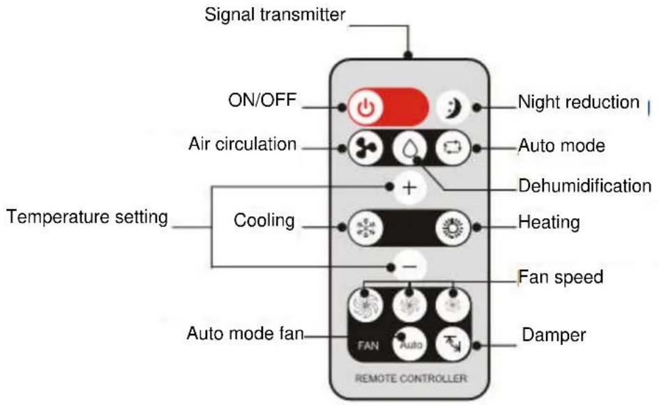
A thin plastic film needs to be removed from the battery when a unit is new. Do this by pulling the piece of plastic that sticks out from the bottom of the battery compartment.
For the remote control to work there must be a clear view of no more than 6 metres from the signal receiver to the remote control.
Handle the remote control with care. Do not drop it on the floor and avoid getting it wet or exposing it to direct sunlight.
Replacing the battery in the remote control
The battery should be changed when the signal strength from the remote control starts to get weaker. Turn the remote control upside down and press the button where it says "Press". Pull out the cover and replace the battery, making sure that the terminals are correctly positioned. The battery is a CR2025.

flowchart
graph LR
    A["Press"] --> B["Pull out"]
    B --> C["Replace"]
If the remote control does not work
The battery could be flat, or the remote control may have broken. You can still start the heat pump by opening the cover on the indoor part and pressing the emergency switch. The heat pump starts in auto mode. Press the emergency switch again to switch off the heat pump..

natural_image
Illustration showing a hand inserting a component into a cylindrical device, with no text or symbols present.USE
Every time you change a setting the heat pump will stop for a few minutes, and then start again. This is to prevent cold starts and unnecessary wear on the compressor. After stopping with the remote control it can take 6-8 minutes before the system starts again. It can take up to 20 minutes before the system starts working at full power when it is first started.
DISPLAY

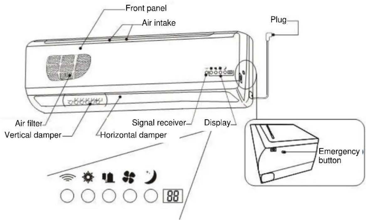
The display is based on very simple logic, with different colours of lamps to explain the operating status. The signal receiver is located on the bottom left-hand side and must never be blocked.
The Mode lamp is in the second ring from the left. The lamp is red when the system is heating, and blue when the system is cooling. In dehumidification mode it is white, in auto mode yellow, and in fan mode green.
The lamp for Output is in the ring in the middle and shows the rate at which the compressor is working. The lamp is red when the compressor is working at high power, yellow for medium power, and green for low power.
The ring for the Fan speed is the second from the right, where the logic is the same as for the compressor speed, i.e. low-medium-high are represented by the colours green-yellow-red.
The ring on the far right shows whether the Night-reduction function is activated. The lamp is yellow when this function is activated, and off when inactivated.
The temperature is shown on the display symbol on the far right. The temperature shows the real temperature when the system is in operation. When the temperature is changed the required temperature is shown briefly, after which the real temperature is shown.
OPERATING MODES
Auto mode

During auto mode the system is controlled automatically and selects cooling, dehumidification or heating on the basis of the set temperature. For home use we recommend that you do not select auto mode, but manually select the required function (i.e. cooling or heating mode). This is because the system does not take other heating methods into consideration, e.g. burning wood in a stove. If the indoor temperature is higher than the set temperature on the pump, it will start to cool instead.
Press the On/Off button to start the system.
Now press the function button for auto mode, see symbol above. The status lamp on the indoor unit will now turn yellow.
The heat pump will now run on a standard program to provide an optimum indoor climate.
The operating modes follow the sequence given below.
| Room temperature during auto mode | Settings |
| 27°C or more | Cooling |
| 21-27°C | Dehumidification |
| 21°C or less | Heating |
Auto mode is not to be recommended from the perspective of economy, and it is better to use the heating or cooling mode.
Cooling

When cooling, the system only cools in relation to the set temperature. This means that the system switches off when the temperature falls below the set temperature.
Press the On/Off button to start the system.
Now press the function button for cooling, see symbol above. The status lamp on the indoor unit will now turn blue.
Adjust the temperature up or down by pressing + or - when you want it to be hotter or cooler. The temperature changes by 1°C each time it is pressed. The set temperature is shown on the right-hand side in the display.
Dehumidification

On days with a high relative humidity the air can feel heavy, and you can get tired. Dehumidification makes the indoor climate more comfortable. The best time to run dehumidification is when the outdoor temperature is between 21 and 27 degrees.
Press the On/Off button to start the system.
Now press the function button for cooling, see symbol above. The status lamp on the indoor unit will now turn white.
The temperature cannot be changed in dehumidification mode.
Air circulation

In air circulation mode the status lamp is green and the air circulates without heating or cooling. This function is recommended when an alternative source of heat, e.g. wood stove, generates concentrated heat and when some extra circulation of the air is wanted without the compressor on the heat pump running.
Heating

The system heats in relation to the set temperature. This means the system switches off when the temperature becomes higher than the set temperature, which ensures maximum economy.
Press the On/Off button to start the system.
Now press the function button for heating, see symbol above. The status lamp on the indoor unit will now turn red. The system starts heating to provide a uniform and comfortable temperature.
Adjust the temperature up or down by pressing + or - when you want it to be hotter or cooler. The temperature changes by 1°C each time it is pressed. The set temperature is shown on the right-hand side in the display.
The temperature setting is shown for about 3-5 seconds on the indoor unit display. When the temperature is adjusted up or down it also changes on the display. After 3-5 seconds the display shows the actual room temperature again. The lowest temperature that can be set is +10°C. The settings are +10°C and +17-31°C. +10°C can only be selected when the system is running in heating mode. Some temperature variations can occur in different rooms. Adjust this by changing the air speed and the temperature until the required indoor temperature is achieved. When the outdoor temperature falls below -20°C the system switches off automatically. This is to avoid unnecessary wear on the compressor and for best heating economy. The system starts automatically when it gets warmer.
Fan speed

The fan has 3 different speeds, which are controlled with the above symbols. Press the different fan symbols to change the speed.

• High speed: the status lamp for fan speed should be red.

• Medium speed: the status lamp for fan speed should be yellow.

• Low speed: the status lamp for fan speed should be green.

The fan also has an automatic function, AUTO, which adjusts the fan speed according to the set temperature and real temperature in the room. This is a simple way of allowing the heat pump to work uninterruptedly.
It is a big advantage to allow the fan to work at a relatively high speed for optimum distribution of the heat, and therefore a manual mode is to be preferred.
Controlling the damper

It is important to achieve a good distribution of the air from the system in relation to the settings. We normally recommend allowing the air to blow as high as possible during cooling and as low as possible during heating, since cold air drops and hot air rises. Press the damper button to change the damper angle. The damper can be changed to 5 different angles, and when pressed for the sixth time will oscillate.

flowchart
graph TD
    A["Step 1"] --> B["Step 2"]
    B --> C["Step 3"]
    C --> D["Step 4"]
    D --> E["Step 5"]
If the indoor unit is installed near the floor the damper should be set in position 1 or 2. If the indoor unit is placed up on the wall the damper should be in position 3, 4 or 5.
Night-reduction
For best energy economy the temperature should be lowered during the night. Night-reduction lowers the temperature by 3irc C in relation to the set temperature. By lowering the temperature in rooms not in use for long periods (more than 5 hours) it is possible to save an additional 10-20% of the power consumption. When the heat pump is set to cooling the temperature will be raised 3irc C in relation to the set temperature. During night-reduction the fan speed is reduced an additional step from the lowest fan speed. This is because the fan noise should be as low as possible if the indoor unit is placed, for example, in a bedroom.
To activate night mode, press the above symbol, after which the status lamp for night-reduction turns yellow. The system will immediately lower the temperature by 3 degrees, and maintain this for 6 hours. After 6 hours the temperature increases to the set temperature. This function will be repeated and as long as it is connected it will perform the same procedure at the same time every day until the function is deactivated.
To deactivate night mode, press the night-reduction button, after which the status lamp for night-reduction goes off.
MAINTENANCE
After every heating season
If you do not intend to use your heat pump for a long period you should dry out the indoor unit before switching off the system. The heat exchanger and drainage system in the indoor unit dry out after circulating the interior air for a few hours.
Before every heating season
Clean the air filter in the indoor unit. The main filter can be washed in lukewarm water. The micro filter and carbon filter should also be replaced.
Important
The plug should never be unplugged from the wall socket during the winter. This is because the heating cables in the outdoor unit will be switched off, and they are intended to protect the system. If the heat pump needs to be switched off, use the remote control. Do not pull out the plug.
Pull out the plug from the wall socket if there is a risk of a thunder storm, because lightning can destroy the system components. Pull out the plug when the heat pump is not going to be used during the summer for a long period, or if you go away.
Switch off the system and pull out the plug before carrying out any form of maintenance on the system.
Filters and cleaning

The front panel needs to be opened to access the filters. Press in the two white buttons on the short sides at the same time. Release the panel by unhooking the two fasteners in the middle of the panel.

natural_image
Diagram of a cylindrical device with internal grid pattern and two upward arrows indicating direction (no text or symbols)Lift the panel straight up and remove the filters.
The filters should be cleaned and replaced before each heating season. They should also be cleaned regularly as long as the system is in use. The filters prevent dust and other particles from penetrating into the fan and heat exchanger. If the filters get filled with dust the capacity of the system to emit cooling or heat will be significantly reduced. It is therefore very important to keep the filters clean. We recommend cleaning the filters at least once a month, more often if necessary, as long as the system is in operation.

natural_image
Illustration of a hand using a tool to clean or mark a small object on a grid surface (no text or symbols)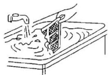
natural_image
Line drawing of a hand washing a sink with water, no text or symbols presentUse a vacuum cleaner to remove the dust on the main filter and then rinse under running lukewarm water, or soak in soapy water for one hour. Rinse the filter and allow to dry before replacing. Never wash the main filter in a washing machine or in water hotter than 50irc C. This could deform the filter. The carbon filter and micro filter should only be vacuum cleaned, or replaced.
natural_image
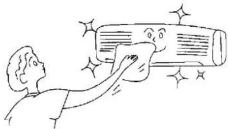
Illustration of a person cleaning a large cylindrical object with sparkles (no text or symbols)When cleaning the framework on the indoor unit, use a soft cloth dipped in mild soapy water. Wring the cloth well. Never use solvents, acids or pesticides on the indoor unit, this could damage the heat pump.
Miscellaneous
The system has a defrosting process that is automatically activated and controlled when the need arises. When defrosting is in progress the system stops, the outdoor unit speeds up and emits a hissing and gurgling noise, after which the system starts up again. This can take place at regular intervals and is quite normal.
If a layer of frost forms, which is not defrosted automatically by the system, raise the indoor temperature a few degrees. If the layer of frost gets thicker and starts to form ice it is possible to force-defrost the system by selecting cooling and lowering the set temperature.
USER TIPS
We recommend following the directions given below for best possible energy-saving economy.
Cooling
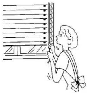
It is important to keep doors and windows closed for the best possible cooling effect. Close the curtains and if possible use sun screens.
natural_image
Simple line drawing of a person looking up at a window with horizontal bars (no text or symbols)Heating
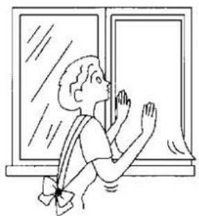
The sun provides a lot of heat even during the winter, and even if it is cold outside. Heating bills can be significantly reduced by allowing as much sunlight in as possible during the day.
natural_image
Illustration of a person waving near a window (no text or symbols)Energy-saving economy
For optimal energy savings it is important that both the indoor unit and outdoor unit have free access to air. Never cover these parts.

natural_image
Illustration of two cartoon-style cards with faces and stress, one showing a broken sheet (no text or symbols)Roof over outdoor unit
Anslut heat pumps are designed to withstand the severe Nordic climate. However, by further protecting the outdoor unit from the weather and wind you can simplify maintenance work. Building a roof over the outdoor unit will, for example, prevent the accumulation of snow and leaves behind the unit. A layer of snow prevents the flow of air and therefore reduces the effect. The heat pump requires an ample supply of air and it must also be possible to access the unit for service purposes. Never place a roof, or walls (for especially severe climatic conditions), closer than 40 cm from the unit. Never cover under any circumstances a protective frame placed in front or under the unit.

natural_image
Cartoon illustration of a smiling refrigerator with sun and cloud, no text or symbols presentWIRING DIAGRAM
INDOOR UNIT

flowchart
graph TD
    A["TO OUTDOOR UNIT"] --> B["SIGNAL CONNECTOR"]
    A --> C["POWER CONNECTOR"]
    A --> D["EXPLICAC CASE"]
    D --> E["INREADABLE"]
    D --> F["POWER PLUG"]
    G["INDOOR UNIT CONTROL"] --> H["FAN MOTOR FM 1~"]
    G --> I["FAN1"]
    G --> J["CON1"]
    G --> K["CN1"]
    G --> L["RT PT"]
    G --> M["SW"]
    G --> N["CN-SMD"]
    G --> O["COIL SENSOR"]
    G --> P["ROOM TEMP SENSOR"]
    G --> Q["STEPS MOTOR SM"]
    G --> R["DISPLAY BOARD"]
    G --> S["TRANSFORMER"]
    G --> T["TAKEOVER BOARD"]
    U["CON1"] --> V["CN1"]
    W["CON1"] --> X["CN1"]
    Y["CON1"] --> Z["CN1"]
    AA["CON1"] --> AB["CN1"]
    AC["CON1"] --> AD["CN1"]
    AE["CON1"] --> AF["CN1"]
    AG["CON1"] --> AH["CN1"]
    AI["CON1"] --> AJ["CN1"]
    AK["CON1"] --> AL["CN1"]
    AM["CON1"] --> AN["CN1"]
    AO["CON1"] --> AP["CN1"]
    AQ["CON1"] --> AR["CN1"]
    AS["CON1"] --> AT["CN1"]
    AU["CON1"] --> AV["CN1"]
    AW["CON1"] --> AX["CN1"]
    AY["POWER PLUG"] --> AZ["YLW/GRN"]
OUTDOOR UNIT

INSTALLATION
Check list
Check list for placement of indoor/outdoor units
• The indoor unit must be placed indoors.
- If possible, the indoor unit should be placed inside an exterior wall to minimise the visible piping indoors.
• Note that all rotating objects produce sound and resonance. Bear this in mind when positioning the indoor unit (e.g. bedroom wall).
- Ensure that the indoor and outdoor walls can bear the weight of the units. In some cases it is advisable to secure the wall's bearing strength by building a metal or wooden frame.
- Do not leave refrigerant pipes from the indoor unit exposed against the wall, as the condensate water that forms on the pipes can damage the wall and floor. Avoid this problem by using the insulation material supplied in the installation kit.
- If possible avoid mounting the outdoor unit on a wooden wall, and use vibration dampers between the wall brackets and the unit's feet.
- If it is not possible to mount the outdoor unit on the house wall, we recommend using concrete blocks or a ground stand.
- When placed in a wind exposed area, the unit should be secured with a metal frame and heavy-duty bolts.
Pay attention to the following
Avoid installing the indoor unit/outdoor unit:
• in direct sunlight,
- in stairwells and hall areas with limited air volume (risk of thermal columns and poor distribution of heat),
• in the vicinity of heat sources that can affect the performance of the system,
• where there are pipes or electrical cables that can be damaged during drilling,
• in kitchens or close to other factory equipment where there can be fumes containing oil,
• where there may be leakage of flammable gas, e.g. in a kitchen fitted with a gas stove,
• Do not place the outdoor unit near bedroom windows if this can be avoided.
- Place the outdoor unit where it will not disturb the surroundings, and fit a roof cover over the unit if possible.
- Do not put the outdoor unit in an enclosed space. The outdoor unit must have free access to outdoor air.
Module system
The module system from Anslut consists of pre-filled pipes and units. The system is pre-filled and evacuated. To minimise the risk of refrigerant leakage it is therefore very important that the spring-loaded shut-off valves in the couplings are not exposed to mechanical stress. Keep the protective plugs on until you have screwed the couplings together. The system is patented and enables the installation of our pre-filled module system to go much faster than the installation of traditional systems. The installation costs for an Anslut air heat pump are consequently low.
Note that these installation instructions are general instructions. Deviations may occur in relation to pre-fitted brackets, contact arrangements for electrical connections, and dimensions etc. Always check the actual design of your model and observe local regulations and rules during installation.
Positioning the outdoor unit
Mount the outdoor unit securely so that is cannot be tipped over.
Use the vibration dampers supplied with the outdoor unit. For installation on material other than concrete it is possible to purchase extra vibration dampers to further reduce the noise. Place the outdoor unit in a safe place, preferably towards the north and with a small roof covering over it. Note that there must be at least 10 cm between the outdoor unit and the wall, at least 4 metres of free access to air in front of the outdoor unit, and at least 40 cm of free space at the sides. Avoid placing the outdoor unit close to bedrooms, and if possible avoid mounting it on a wooden wall. Allow the drainage water to run freely from the outdoor unit. Do not fit drain hoses on the outdoor unit for condensation water. The water can freeze and prevent drainage, resulting in damage.
Tools
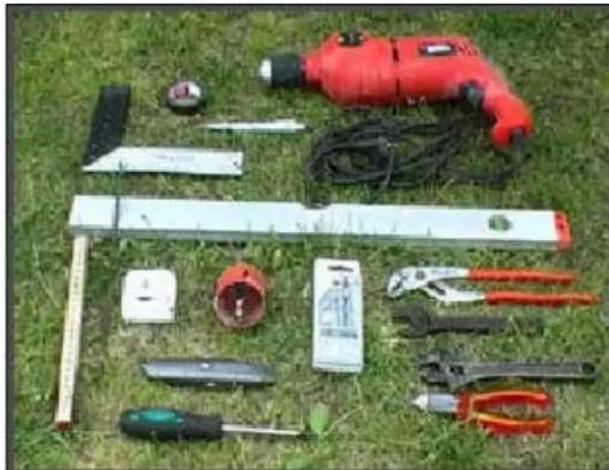
Only standard tools are needed for the installation: spirit level, pencil, crosshead screwdriver, drill, 8 mm concrete drill bit, detection drill, square, tape measure or ruler, tape width approx. 65 mm, hole saw approx. 80 mm (deviation in size may occur), knife and two adjustable spanners or pliers (torque wrench where applicable).
natural_image
Assorted tools laid out on grass, including a red drill, pliers, and tools (no visible text or labels)Indoor unit
The indoor unit consists of a separate wall bracket, pre-fitted pipe parts with screw coupling, drainage hose, carbon filter and micro filter, and remote control with wall bracket. The box also includes the screw needed to mount the indoor unit of a wooden or concrete wall.

natural_image
Simple line drawing of a mechanical component or bracket (no text or symbols)Outdoor unit
The outdoor unit consists of 2 wall brackets, 4 vibration dampers and mounting bolts for masonry and concrete walls. The outdoor unit has pre-fitted pipe sections fitted with screw couplings (non-return valves).

natural_image
Close-up of a mechanical device with attached components and a yellow label (no visible text or symbols)
natural_image
Technical line drawing of an air conditioner internal component (no text or symbols)
natural_image
Exterior view of a modern office building (no signage)Installation kit
The installation kit consists of two gas-filled pipes, drainage hose, sealant, diffusion tape, 2 pipe insulation sections, cable ties and electrical cable with connector arrangement for connecting the indoor unit to the outdoor unit.
NOTE Do not remove the plastic plugs on the pipe sections before starting to install the pipes.
Positioning of indoor unit
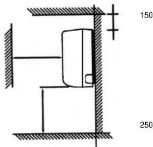
The indoor unit should be placed in the room where the most comfortable temperature is required. It should not be placed directly opposite or over sofa and armchairs. The indoor unit must not be placed closer than 25 cm to the floor or 15 cm to the ceiling, with a minimum free space of 15 cm on the sides. The important thing is to have free space round the indoor unit to ensure the best distribution of the air. If placed close to the floor the dampers should be aligned upwards, since the outflow temperature can reach over 60°C. Wooden floors can shrink if the indoor unit blows for too long on the same place, or at too close a range. If the main purpose of the system is to provide heating the indoor unit should be placed lower down on the wall, since heat rises. Keep as much open space as possible round the indoor unit for the best possible air flow. Place the indoor unit on an outer wall to simplify the routing of the pipes. Note that a gradient is needed for the condensation hose.

natural_image
Assorted white cable and hose components including wires, connectors, and a coiled hose (no visible text or symbols)
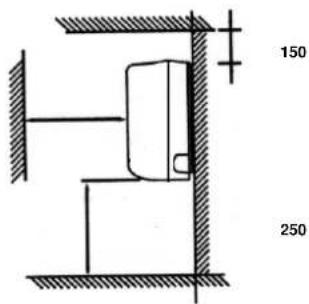
IMPORTANT
Always mount the indoor unit horizontally.
Piping alternatives:

Fitting the wall bracket for the indoor unit
Once the position for the heat pump has been decided it needs to be mounted. Mark up where on the wall the wall bracket (designs vary according to model) is to be fitted. Note that it must be fitted horizontally. The position of bracket determines where the hole for the cooling pipe is to be drilled.
Hole-making
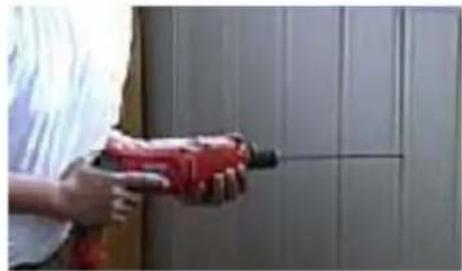
The position of the wall bracket determines where the hole to the refrigerant pipe should be drilled. The hole should be behind the indoor unit on the right-hand side, so that the hole is completely covered by the indoor unit when it is installed. Measure up by using the centre of the wall bracket and the centre of the indoor unit to the centre of the hole for the refrigerant pipe. The lower edge of the hole should be approx. 0.5 cm within the lower edge of the indoor unit.
- It is very important to bear in mind that the hole must have a gradient to the outer wall so that the drainage water can run out freely. A minimum gradient of 1 cm per 10 cm.
- Start by drilling with the detection drill to check that there are no obstacles in the way and that the hole on the outside will be correct. Use the detection drill to check that there is nothing in the way in the wall.
- If there is nothing obstructing the detection drill, the wall bracket can be fitted and the hole (approx. 80 mm) drilled. Check the dimension in relation to the supplied wall inlet.
- Set the drill at low speed to prevent a build-up of heat and clogging of the hole saw. It is also an advantage to pre-drill with a 12-15 mm bit so that any sawdust in the wall can run out.
natural_image
Person using a red power drill on a wall-mounted cabinet (no visible text or symbols)
natural_image
Person using a red drill bit on a wall socket (no visible text or symbols)Mounting the indoor unit
Fit the 4-wire electric cable with quick connector that connects the indoor and outdoor units before mounting the indoor unit. The electric cable is connected on the right-hand side at the back of the indoor unit. Press the connectors together and fit the cable.
The drainage hose should also be fitted, which is also placed on the right-hand side on the back of the indoor unit.
Never connect the power before the pipes have been routed and the system modules are connected.
The indoor unit can now be mounted on the wall bracket. Start by bending out the pipe sections so that they go straight out from the back of indoor unit. Thread the electric cable through the hole. Lift up the indoor unit and insert the pipe and drainage hose through the wall, as shown in the illustration. Now secure the indoor unit on the wall bracket. Avoid vibrations by mounting the indoor unit horizontally and flush to the wall.

natural_image
Technical line drawing of a mechanical device with three separate views below (no text or symbols)
natural_image
Two-panel image: left shows a person adjusting a black object indoors; right shows a close-up of a blue wooden structure with wires and tools (no visible text or symbols)Wall inlet
Measure and cut the wall inlet to the required length. Insert the wall inlet from outside. Glue the wall inlet secure with silicone.

natural_image
Pure mechanical diagram showing a cylindrical component inserted into a vertical rod (no text or symbols)
natural_image
Close-up of hands installing a black and white hose component on a wooden surface (no text or symbols visible)Positioning of the outdoor unit
It is now time to mount the outdoor unit. The unit should be placed where there is good access to outdoor air, not in a shed or garage etc. There must be at least 4 m of free space in front of the outdoor unit, and at least 10 cm between the back of the outdoor unit and the wall. You must also take into account that water runs from the outdoor unit during the defrosting process. Heating cables in the bottom tray ensure that water does not freeze in the unit. However, ice may form on the ground where the drain runs out.
Outdoor unit brackets
The brackets should, if possible, be fitted on a brick wall. Make sure to use suitable and stable attachments if mounting the unit on a wooden wall. A ground stand is recommended for wooden walls. Fit the brackets with a centre distance of 505 mm (does not apply to 416-086) and at least half a metre above the ground. In areas with a lot of snow the distance to the ground should be increased to ensure a good air supply and drainage.

natural_image
Man working on a metal shelf with tools, no visible text or symbols
Mounting the outdoor unit
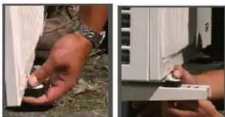
The outdoor unit is placed on the wall brackets with vibration dampers under the unit's feet. Do not tighten the nuts too hard to avoid compressing the rubber. This will reduce the vibration damping properties of the rubber. To ensure an adequate air flow, the distance between the wall and outdoor unit must not be less than 10 cm.
NOTE: Check that the outdoor unit is horizontal. It is very important that the outdoor unit does not lean forward too much, or to the right. If necessary, adjust with additional shims under the feet.
natural_image
Two-panel photo showing hands interacting with a wall-mounted device; no visible text or symbols.Installing the refrigerant pipes
Start the installation of the pipe kit at the indoor unit and then straighten out the pipes successively. First bend the pipe from the indoor unit in the direction of the outdoor unit. The drainage hose should lie in the bottom of the hole. Start the bend for the pipe inside the hole, so that there is a smooth bend to the outer wall. It is very important not to bend the pipe to the edge of the hole, this can cause a wrinkle in the pipe which can prevent the through flow of the refrigerant. Repair any wrinkles in the pipe before connecting the installation kit.
There are protective caps on the pipe ends, which must be screwed off before fitting. It is very important to keep the coupling completely clean and free from moisture. On the ends of the pipe lengths (installation kit) there are two loose screw couplings. There are two fixed nipples on the pre-fitted pipe sections on the units. The loose screw couplings on the pipe lengths must be screwed to the fixed nipples on the units. These cannot be installed incorrectly, but it is very important when connecting that the nipple is held in a fixed position, while the second spanner screws on the coupling.
Now connect the pipes from the installation kit with the fixed nipples on the indoor unit couplings. Start by screwing together all the screw couplings by hand. Use the spanners to tighten the coupling.

natural_image
Close-up of hands holding a golden pipe fitting (no visible text or symbols)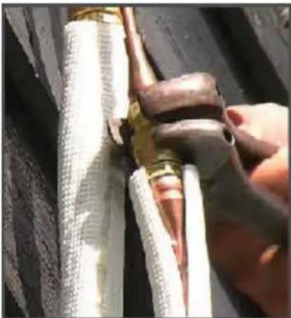
natural_image
Close-up of hands adjusting a flexible hose with mesh insulation (no visible text or symbols)Complete the connection without stopping (a hissing sound may be heard), and use a counterhold to properly tighten the coupling. Minimum tightening torque 18 Nm. Use a torque wrench when in doubt.
Never under any circumstances tighten the fixed nipples with the spanner, only use one of the spanners as a counterhold when connecting. Note also that without a counterhold there is a risk of turning the indoor unit nipples too much so that they break. The couplings must be retightened about 24 hours after the installation.
IMPORTANT
Note that the pipes in the installation kit are filled with gas and must not be cut under any circumstances. The plastic plugs on the ends of the pipe must not be removed until the pipes are to be connected. If the pipes are bent, and cause leakage, the couplings must be loosened so that the non-return valves close.
Pipe routing
IMPORTANT
Continue with the pipe from the indoor unit to the outdoor unit and connect together in the same way. The radius of pipe bends must not be less than 15 cm. Use a cardboard template to check this. Run the electric cable together with the pipes. Produce the bends successively and carefully. Do not bend the pipe directly against, for example, the edge of the hole in the wall. Radius 15 cm
Drainage hose
The drainage hose from the indoor unit is routed together with the pipe and electric cable to the outdoor unit. Make sure that there is a gradient on the hose all the way to the outlet to avoid the formation of a water trap in which water can accumulate and freeze during the winter. Cut the drainage hose to size, to allow the water to be released at a suitable place.
Radius 15 cm

natural_image
Pure geometric diagram showing concentric curved lines and a circle with crosshairs, no text or symbols present.Connecting the installation kit
- On the ends of the pipe lengths (installation kit) there are two loose screw couplings. There are two fixed nipples on the pre-fitted pipe sections on the outdoor unit. The loose screw couplings on the pipe lengths must be screwed to the fixed nipples on the units. These cannot be installed incorrectly, but it is very important when connecting that the nipple is held in a fixed position, while the second spanner screws on the coupling.
- Connect the pipes from the installation kit with the fixed pipes fitted on the outdoor unit. Start by screwing together all the screw couplings by hand.

natural_image
Close-up of a hand adjusting a mechanical component with a yellow tool (no visible text or symbols)
natural_image
Close-up of hands using a tool to adjust or install electronic components on a white device (no visible text or symbols)- Use the spanners to tighten the coupling. Complete the connection without stopping (a hissing sound may be heard), and use a counterhold to properly tighten the coupling. - Never under any circumstances tighten the fixed nipples with the spanner, only use the spanner as a counterhold when coupling. Note also that without a counterhold there is a risk of turning the outdoor unit nipples too much so that they break. Retighten the couplings about 12-24 hours after installation.
- Check the tightness of the couplings by applying some soap and water. Check that there are no bubbles.
- Recheck the tightness and retighten the couplings again 12-24 hours after installation. Check the tightness by wetting with soapy water. Check also the couplings at the indoor unit. If there are no bubbles, the couplings are correctly connected and tightened.

natural_image
Close-up of hands installing or adjusting a mechanical component with copper and brass parts (no visible text or symbols)Electrical connection - indoors
IMPORTANT
Never connect the power before the wiring arrangement below is connected and the protective covers are refitted. The system is connected to the mains supply with a plug, i.e. it requires no intervention in the electrical system in the house.
Electrical connection – outdoor unit

natural_image
Interior view of an electronic device showing wiring and a connector (no visible text or symbols)Unscrew the cover in front of the terminal block on the outdoor unit.
Press the connectors together and fit the cable with the help of a strain reliever.
Note that the cable from the indoor unit must be fitted under the strain reliever.
Error codes
In the event of a fault in the system an error code will be shown in the display for the temperature in the indoor unit.
| Sequence Fault | Error code | |
| 1 | Fault on hot gas sensor in outdoor unit | E8 |
| 2 | Communication fault between indoor and outdoor part | E0 |
| 3 | Compressor fault | E4 |
| 4 | Fault on outdoor temperature sensor | E7 |
| 5 | Fault on defrost sensor in outdoor unit | E3 |
| 6 | Fault on room temperature sensor in indoor part | E1 |
| 7 | Fault on gas sensor in indoor part | E2 |
| 8 | Fault on current sensor | EA |
| 9 | Fault on voltage sensor | EU |
| 10 | IPM fault | E9 |
| 11 | Communication fault in outdoor unit | EC |
| 12 | Fault on fan motor indoors | E6 |
| 13 | Fault on circuit board outdoors | EE |
| 14 | Fault on circuit board indoors | E5 |
Safety
If a safety mechanism has been activated in the system a safety code will be shown in the display for the temperature in the indoor unit.
Sequence Fault Error code
| 1 | Hot gas temperature too high | P1 |
| 2 | Gas temperature too high indoors in heating mode | P7 |
| 3 | Temperature too high on defrost sensor in cooling mode | P8 |
| 4 | Voltage too high P3 | |
| 5 | Current too high P4 | |
| 6 | Not used - | |
| 7 | Overheating of control P6 | |
| 8 | Overheating of IPM P2 | |
| 9 | Run mode protection P9 |
TECHNICAL DATA
| Anslut 417030 | |
| Refrigerant R410A | |
| COP | 4,5 |
| For homes up to* | 160 m2 * |
| Heat output max. | 5300 W |
| Cooling capacity max. | 4100 W |
| Power consumption comp. system - heating | 410 - 1600 W |
| Power consumption comp. system - cooling | 370 - 1800 W |
| Nominal heat output | 4900 Watts |
| Operating range | -20°C - +40°C |
| Dehumidifying capacity in c oling mode | 1.7 l/h |
| Maximum air flow from indoor unit | 650 m3/h |
| 10°C minimum heating function | Yes |
| Night-reduction function | Yes |
| Automatic defrosting | Yes |
| Heating cable for defrosting | Yes |
| Preheating of compresso | Yes |
| Electronic expansion valve | Yes |
| Restart after power failure | Yes |
| Compressor | Panasonic Inverter Rotary |
| Noise level, indoor unit | 38 dB |
| Noise level, outdoor unit | 47 dB |
| Weight of indoor unit | 10 kg |
| Weight of outdoor unit | 33 kg |
| Dimensions of indoor unit w x h x d | 915 x 185 x 290 mm |
| Dimensions of outdoor unit w x h x d | 780 x 255 x 590 mm |
| Installation kit 4 metres included | Yes, with quick-coupling |
| Supply voltage, earthed** | 230 Volt, 50 Hz, 10 A |
| Residual current device and surge protection | Required |
* This figure is an estimate and depends on insulation and climate in home.
** Delay action fuse
SERVICE BOOKLET
Congratulations on your new heat pump. You have chosen a product that will supply you with wonderful warmth at a low cost over the years to come. Your dealer or installer must carry out an installation inspection and sign the inspection report when the unit is installed. It is important to carry out inspection, maintenance and service at regular intervals to guarantee a long useful life and the full benefits of your heat pump. The first service must be carried out within one year of installation. Servicing must then be carried out as and when necessary, but at least every two years. Servicing must only be carried out by authorised personnel. The following must be checked:
- Function.
• Measuring of overpressure and underpressure.
• Measuring of outdoor temperature. - Cleaning of filters.
- Cleaning of evaporator.
Good luck!
Service 1 OK Fault Specify fault
| Function test: | ☐ ☐ | ____ |
| Overpressure: | ☐ bar | |
| Suction pressure: | ☐ bar | |
| Refilling: | ☐ | Refill volume: ____ gram |
| Set water temperature: °C | ☐ | |
| Set temp. room sensor: °C | ☐ | |
| Outdoor temperature: | ☐ °C | |
| Cleaning of evaporator: | ☐ | |
| Cleaning of filters: | ☐ |
Service completed as per specifications. Next service: ____
Dealer: Date, signature:
Service 2 OK Fault Specify fault
| Function test: | ☐ ☐ | ____ |
| Overpressure: | ☐ bar | |
| Suction pressure: | ☐ bar | |
| Refilling: | ☐ | Refill volume: ____ gram |
| Set water temperature: °C | ☐ | |
| Set temp. room sensor: °C | ☐ | |
| Outdoor temperature: | ☐ °C | |
| Cleaning of evaporator: | ☐ | |
| Cleaning of filters: | ☐ |
Service completed as per specifications. Next service: ____
Dealer: Date, signature:
Service 3 OK Fault Specify fault
| Function test: | □ □ | ____ |
| Overpressure: | □ bar | |
| Suction pressure: | □ bar | |
| Refilling: | □ | Refill volume: ____ gram |
| Set water temperature: °C | □ | |
| Set temp. room sensor: °C | □ | |
| Outdoor temperature: | □ °C | |
| Cleaning of evaporator: | □ | |
| Cleaning of filters: | □ |
Service completed as per specifications. Next service: ____
Dealer: Date, signature:
Service 4 OK Fault Specify fault
| Function test: | ☐ ☐ | ____ |
| Overpressure: | ☐ bar | |
| Suction pressure: | ☐ bar | |
| Refilling: | ☐ | Refill volume: ____ gram |
| Set water temperature: °C | ☐ | |
| Set temp. room sensor: °C | ☐ | |
| Outdoor temperature: | ☐ °C | |
| Cleaning of evaporator: | ☐ | |
| Cleaning of filters: | ☐ |
Service completed as per specifications. Next service:
Dealer: Date, signature:
Service 5 OK Fault Specify fault
| Function test: | ☐ ☐ | ____ |
| Overpressure: | ☐ bar | |
| Suction pressure: | ☐ bar | |
| Refilling: | ☐ | Refill volume: ____ gram |
| Set water temperature: °C | ☐ | |
| Set temp. room sensor: °C | ☐ | |
| Outdoor temperature: | ☐ °C | |
| Cleaning of evaporator: | ☐ | |
| Cleaning of filters: | ☐ |
Service completed as per specifications. Next service: ____
Dealer: Date, signature:
Service 6 OK Fault Specify fault
| Function test: | ☐ ☐ | ____ |
| Overpressure: | ☐ bar | |
| Suction pressure: | ☐ bar | |
| Refilling: | ☐ | Refill volume: ____ gram |
| Set water temperature: °C | ☐ | |
| Set temp. room sensor: °C | ☐ | |
| Outdoor temperature: | ☐ °C | |
| Cleaning of evaporator: | ☐ | |
| Cleaning of filters: | ☐ |
Service completed as per specifications. Next service: ____
Dealer: Date, signature:
Service 7 OK Fault Specify fault
| Function test: | □ □ | ____ |
| Overpressure: | □ bar | |
| Suction pressure: | □ bar | |
| Refilling: | □ | Refill volume: ____ gram |
| Set water temperature: °C | □ | |
| Set temp. room sensor: °C | □ | |
| Outdoor temperature: | □ °C | |
| Cleaning of evaporator: | □ | |
| Cleaning of filters: | □ |
Service completed as per specifications. Next service: ____
Dealer: Date, signature:
Service 8 OK Fault Specify fault
| Function test: | □ □ | ____ |
| Overpressure: | □ bar | |
| Suction pressure: | □ bar | |
| Refilling: | □ | Refill volume: ____ gram |
| Set water temperature: °C | □ | |
| Set temp. room sensor: °C | □ | |
| Outdoor temperature: | □ °C | |
| Cleaning of evaporator: | □ | |
| Cleaning of filters: | □ |
Service completed as per specifications. Next service:
Dealer: Date, signature:
Service 9 OK Fault Specify fault
| Function test: | □ □ | ____ |
| Overpressure: | □ bar | |
| Suction pressure: | □ bar | |
| Refilling: | □ | Refill volume: ____ gram |
| Set water temperature: °C | □ | |
| Set temp. room sensor: °C | □ | |
| Outdoor temperature: | □ °C | |
| Cleaning of evaporator: | □ | |
| Cleaning of filters: | □ |
Service completed as per specifications. Next service: ____
Dealer: Date, signature:
Service 10 OK Fault Specify fault
| Function test: | □ □ | ____ |
| Overpressure: | □ bar | |
| Suction pressure: | □ bar | |
| Refilling: | □ | Refill volume: ____ gram |
| Set water temperature: °C | □ | |
| Set temp. room sensor: °C | □ | |
| Outdoor temperature: | □ °C | |
| Cleaning of evaporator: | □ | |
| Cleaning of filters: | □ |
Service completed as per specifications. Next service: ____
Dealer: Date, signature:
Jula reserves the right to make changes. In the event of problems, please contact our service department.
www.jula.com

Care for the environment!
Must not be discarded with household waste! This product contains electrical or electronic components that should be recycled. Leave the product for recycling at the designated station e.g. the local authority's recycling station.
- Operating Instructions for Heat Pump Air/Air
- SVENSKA 7
- HANDHAVANDE
- Uppvärmning
- Energiekonomi
- INNEDEL
- UTEDEL
- MONTERING
- Checklista
- Inomhusdel
- Utomhusdel
- Monteringskit
- VIKTIGT!
- Utomhusdelens placering
- DRIFT
- Oppvarming
- Energiøkonomi
- Tak til utedelen
- Sjekkliste
- Monteringssett
- Montering av utedel
- Elektrisk tilkobling innedel
- VIKTIG!
- OBSŁUGA
- Ogrzewanie
- Oszczędność energii
- SCHEMAT POŁĄCZEŃ
- CZEŚĆ WEWNETRZNA
- CZEŚĆ ZEWNETRZNA
- MONTAŻ
- Lista kontrolna
- Część wewnętrzna
- Część zewnętrzna
- Zestaw montażowy
- WAŻNE!
- Read the Operating Instructions carefully before use!
- GUARANTEE TERMS AND CONDITIONS
- General conditions
- Dear Customer,
- Other conditions
- GENERAL INFORMATION
- Important before installation
- ELECTRICAL SAFETY
- Important information
- DESCRIPTION
- Indoor unit
- Outdoor unit
- REMOTE CONTROL
- Using the remote control
- Replacing the battery in the remote control
- If the remote control does not work
- USE
- DISPLAY
- OPERATING MODES
- Auto mode
- Cooling
- Dehumidification
- Air circulation
- Heating
- Fan speed
- Controlling the damper
- Night-reduction
- MAINTENANCE
- After every heating season
- Before every heating season
- Important
- Filters and cleaning
- Miscellaneous
- USER TIPS
- Energy-saving economy
- Roof over outdoor unit
- INSTALLATION
- Check list
- Pay attention to the following
- Module system
- Positioning the outdoor unit
- Tools
- Installation kit
- Positioning of indoor unit
- Fitting the wall bracket for the indoor unit
- Hole-making
- Mounting the indoor unit
- Wall inlet
- Positioning of the outdoor unit
- Outdoor unit brackets
- Mounting the outdoor unit
- Installing the refrigerant pipes
- Pipe routing
- Drainage hose
- Connecting the installation kit
- Electrical connection - indoors
- Electrical connection – outdoor unit
- Error codes
- Safety
- SERVICE BOOKLET
- Care for the environment!
Brand : Anslut
Model : 417-030
Category : Air Conditioning