
PIO6L03IX - Range hood VOX - Free user manual and instructions
Find the device manual for free PIO6L03IX VOX in PDF.


| Brand | VOX |
| Model | PIO6L03IX |
| Product Type | Range Hood |
| Rated Voltage | 220-240 V~ 50 Hz |
| Motor Input Power | 115 W |
| Lighting | 1.5 W LED |
| Number of Speeds | 2 (Low and High) |
| Minimum Duct Diameter | 120 mm |
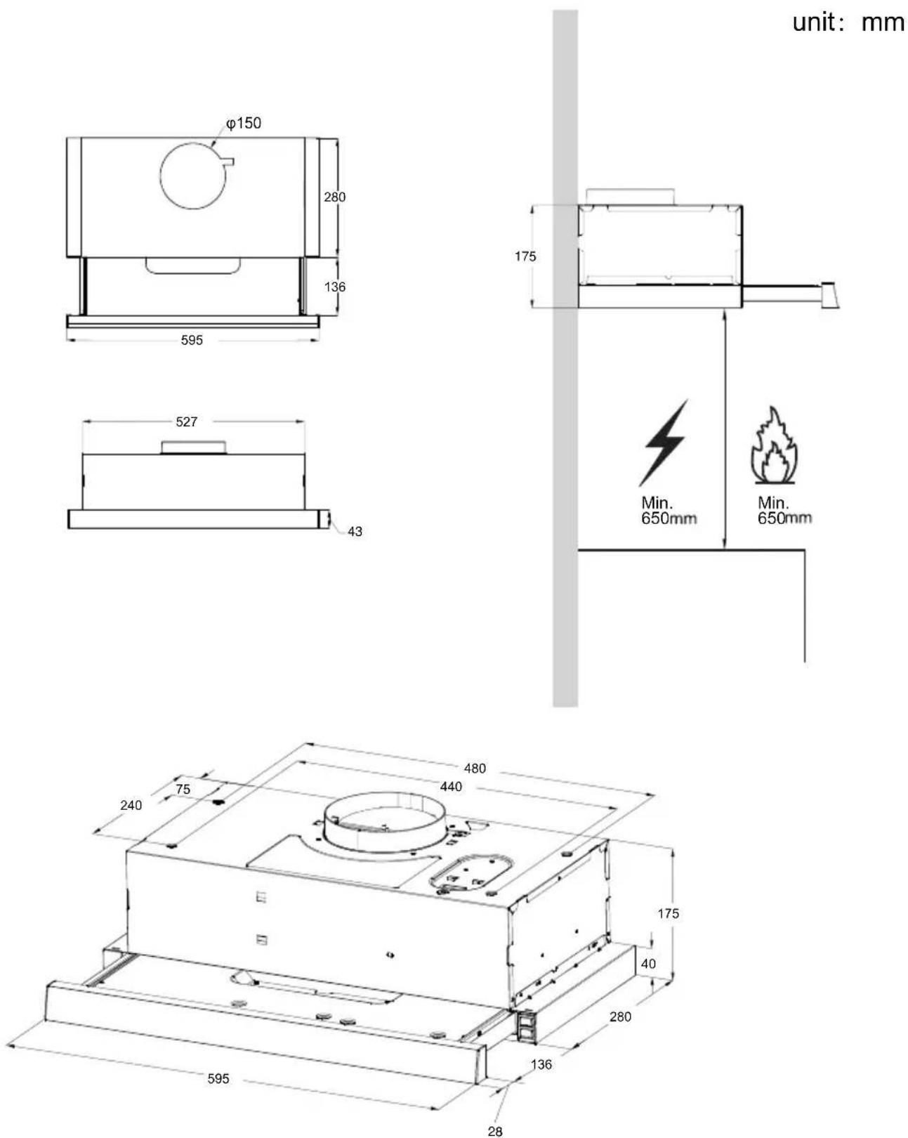
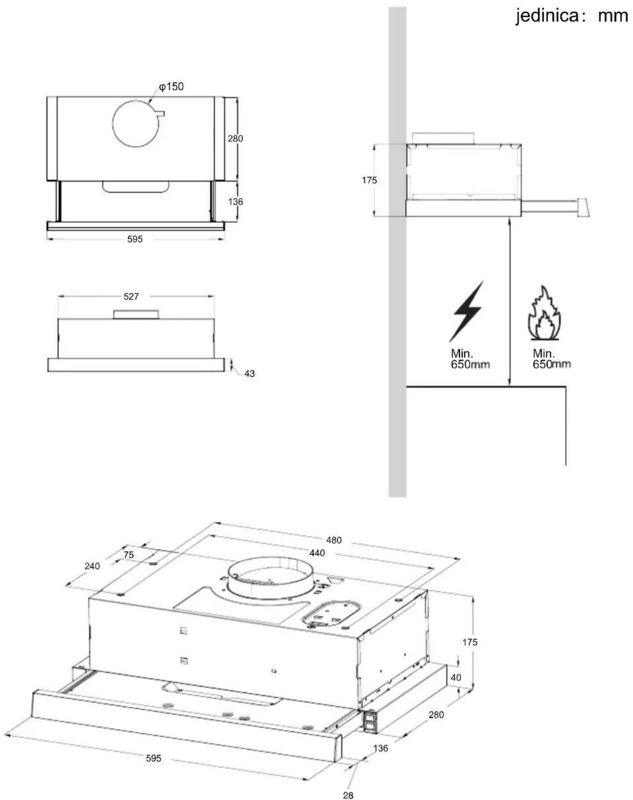
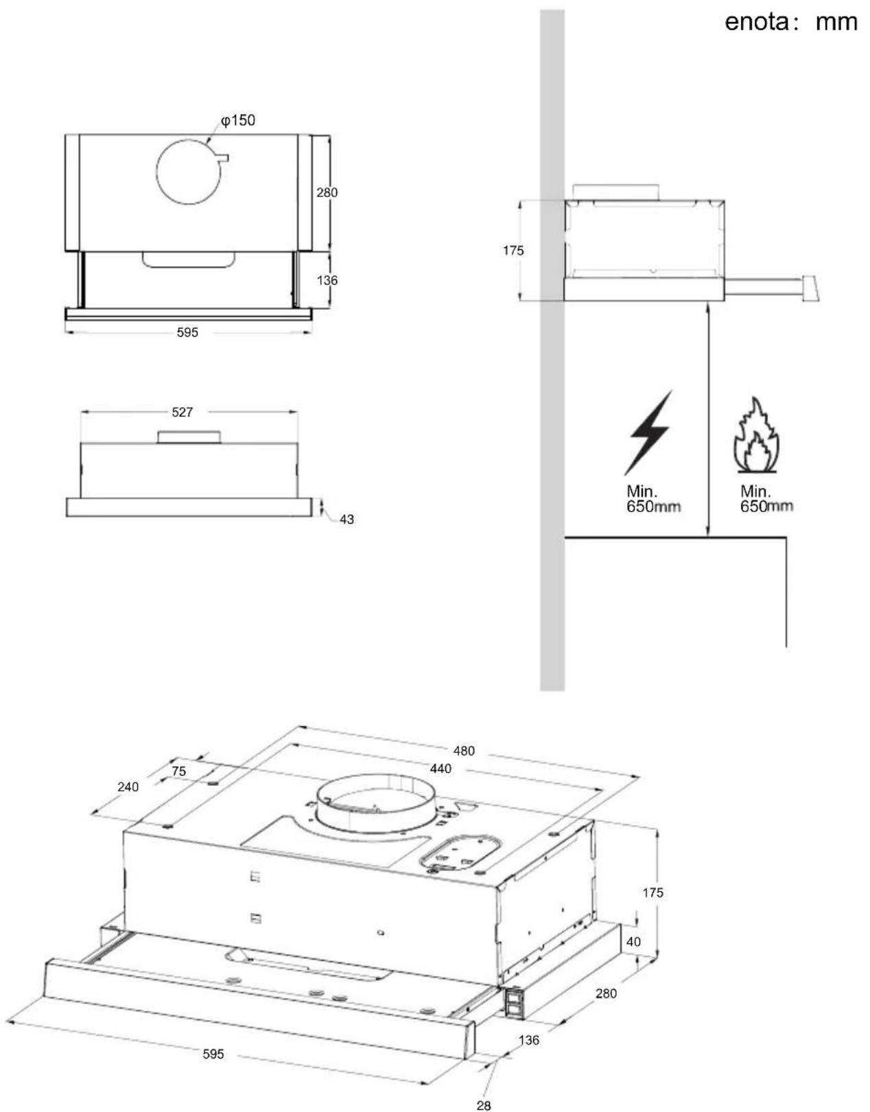
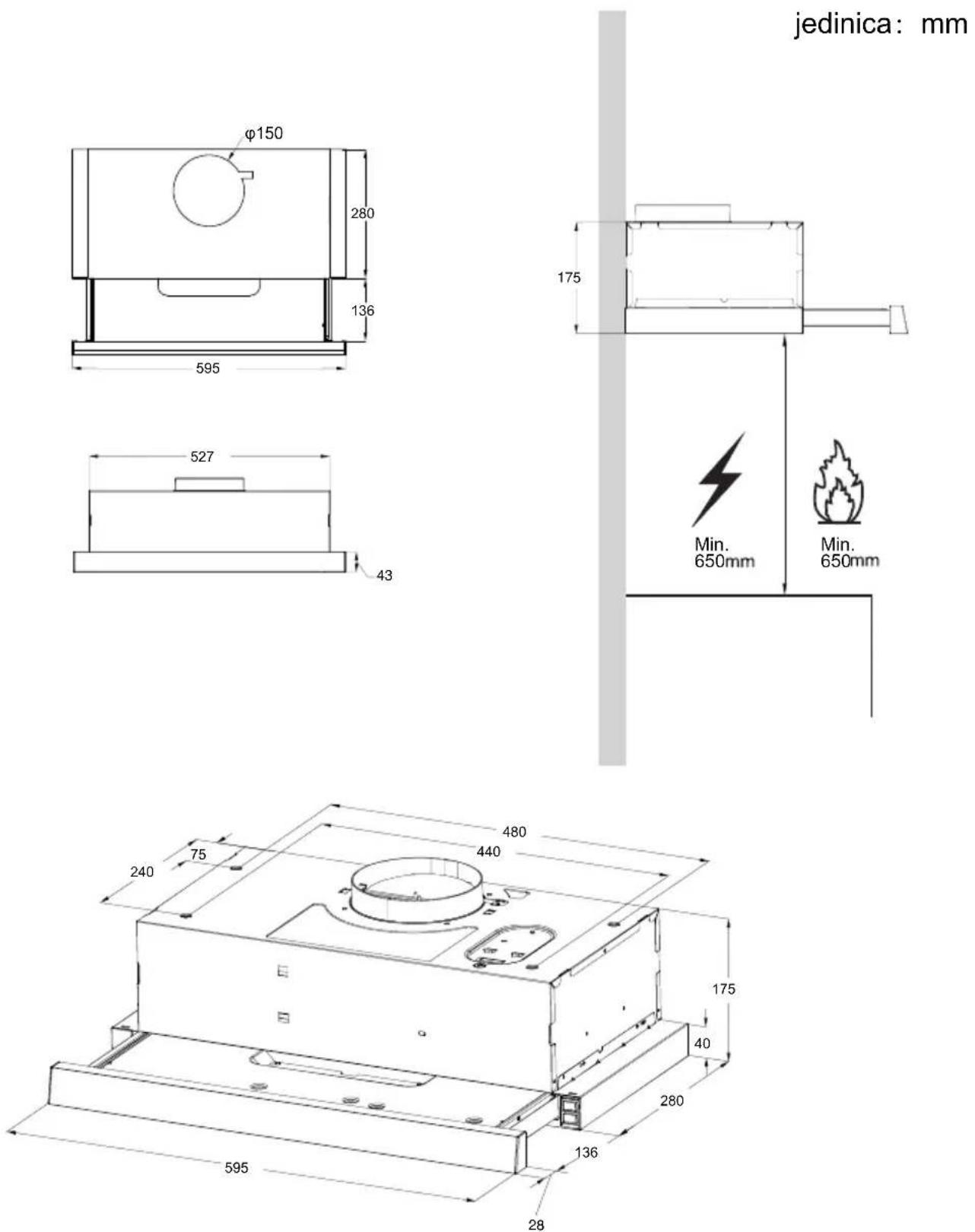
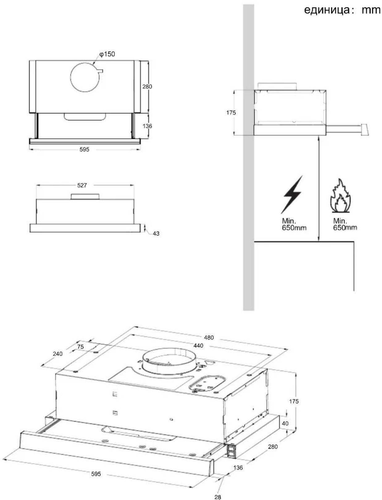
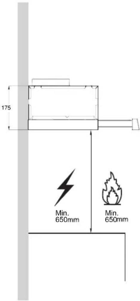
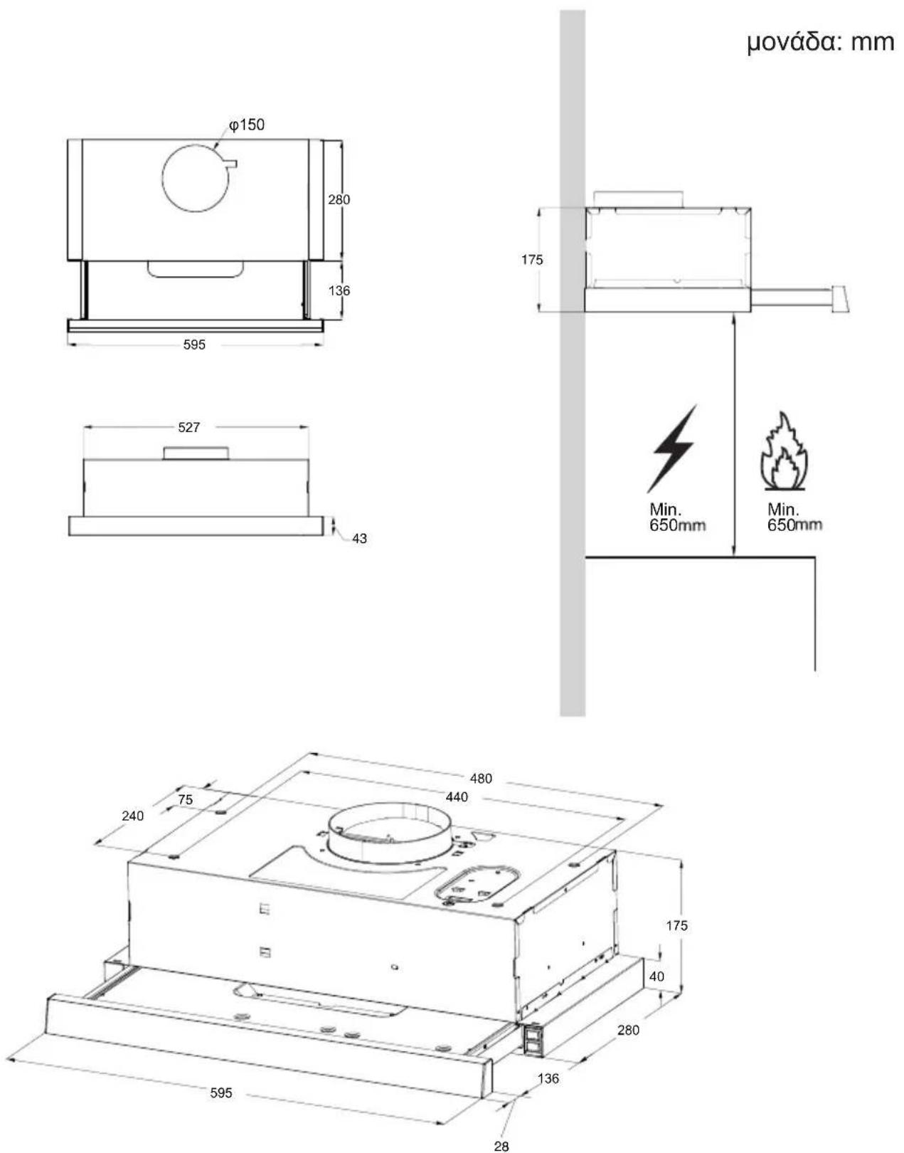
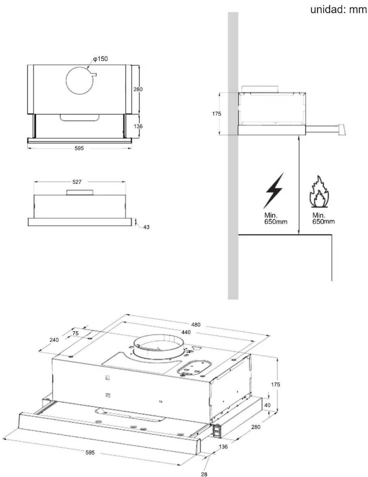
| Minimum Distance from Hob | 650 mm |
| Grease Filter Type | Metal self-supporting, washable |
| Grease Filter Cleaning Interval | Every 2 months |
| Activated Charcoal Filter | Optional, replace every 4 months |
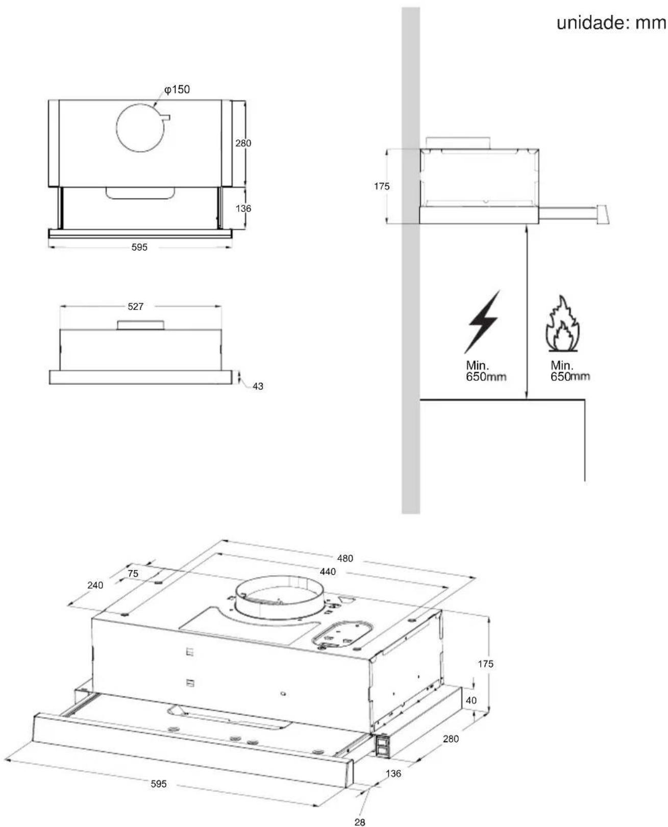
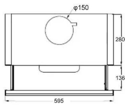
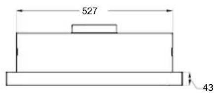
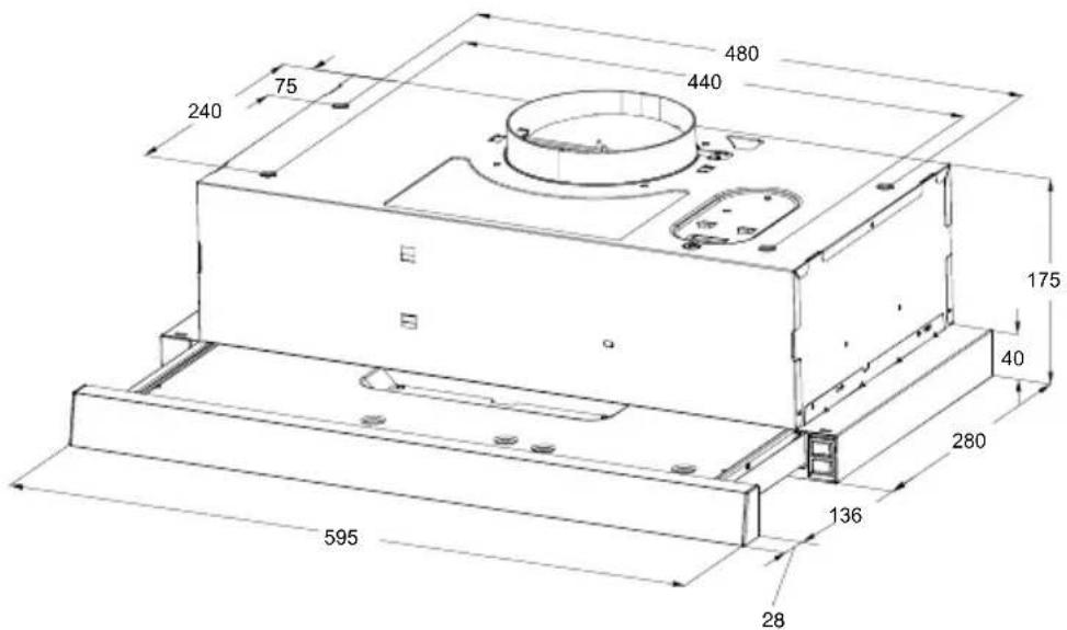
| Dimensions (W x D x H) | 595 x 280 x 136 mm |
| Installation Types | Built-in or wall-mounted |
| Venting Modes | Extraction or recirculation |
| Maximum Number of Hob Elements | 4 |
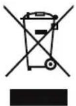
| Disposal | Separate collection for WEEE per EU Directive 2012/19/EU |
| Safety Features | Class I appliance, earthing required; caution: accessible parts may get hot |
| Replacement Parts | LED light (1.5W, type DBS-1.5-H-33.2/120), grease filters, charcoal filters |
Frequently Asked Questions - PIO6L03IX VOX
User questions about PIO6L03IX VOX
0 question about this device. Answer the ones you know or ask your own.
Ask a new question about this device
Download the instructions for your Range hood in PDF format for free! Find your manual PIO6L03IX - VOX and take your electronic device back in hand. On this page are published all the documents necessary for the use of your device. PIO6L03IX by VOX.
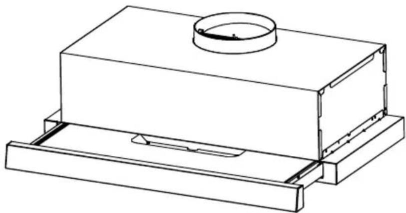
USER MANUAL PIO6L03IX VOX
natural_image
Technical line drawing of a rectangular housing with a circular top component and base support (no text or symbols)COOKER HOOD
INSTRUCT ON MANUALI
Read this manual carefully before operation
Pictures in this manual are for reference only, the product in kind prevail.

The instructions for Use apply to several versions of this appliance. Accordingly, you find descriptions of individual features that do not apply to your specific appliance.
INSTALLATION
● The manufacturer will not be held liable for any damages resulting from incorrect or improper installation.
- Check that the mains voltage corresponds to that indicated on the rating plate fixed to the inside of the hood.
- For Class I appliances, check that the domestic power supply guarantees adequate earthing.
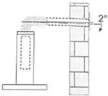
● Connect the extractor to the exhaust flue through a pipe of minimum diameter 120mm.
● The route of the flue must be as short as possible.
- Do not connect the extractor hood to exhaust ducts carrying combustion flumes (boilers, fireplaces, etc.).
- If the instructions for installation for the gas hob specify a greater distance specified above, this has to be taken into account.
- If the supply cord is damaged, it must be replaced by the manufacturer or its service agent or a similarly qualified person in orderto avoid a hazard.
● The air must not be discharged into a flue that is used for exhausting fumes from appliances burning gas or other fuels (not applicable to appliances that only discharge the air back into the room).
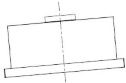
● The minimum distance between the supporting surface for the cooking vessels on the hob and the lowest part of the range hood is 650 mm.
● Regulations concerning the discharge of air have to be fulfilled.
natural_image
Simple line drawing of a heating lamp with a control panel and smoke rising (no text or symbols)USE
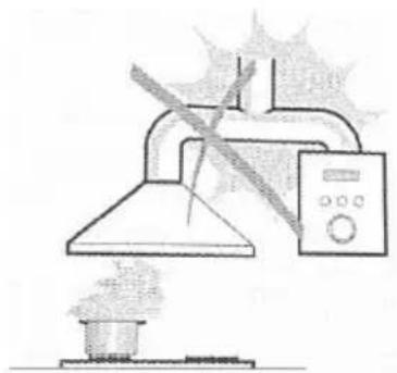
● The extractor hood has been designed exclusively for domestic use to eliminate kitchen smells.
● Never use the hood for purposes other than for which it has been designed.
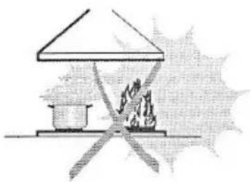
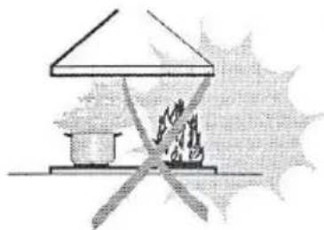
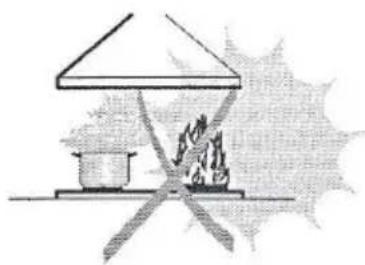
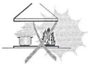
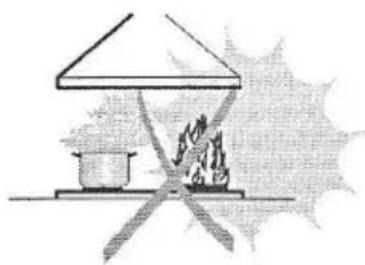
● Never leave high naked flames under the hood when it is in operation.
- Adjust the flame intensity to direct it onto the bottom of the pan only, making sure that it does not engulf the sides.
- Deep fat fryers must be continuously monitored during use: overheated oil can burst into flames.
- This appliance is not intended for use by persons (including children) with reduced physical, sensory or mental capabilities, or lack of experience and knowledge, unless they have been given supervision or instruction concerning use of the appliance by a person responsible for their safety.
● Children should be supervised to ensure that they do not play with the appliance.
- There shall be adequate ventilation of the room when the range hood is used at the same time as appliances burning gas or other fuels (not applicable to appliances that only discharge the air back into the room).
● There is a fire risk if cleaning is not carried out in accordance with the instructions.
● Do not flame under the range hood.
- "CAUTION: Accessible parts may become hot when used with cooking appliances".
MAINTENANCE
● The cooker hood and its filter should be cleaned regularly according to the instruction.
- Switch off or unplug the appliance from the mains supply before carrying out any maintenance work.
● Clean the hood using a damp cloth and a neutral liquid detergent.
● The appliance uses 4 hob elements at most.

natural_image
Simple line drawing of a house with a stove and fire, no text or symbols presentThe symbol is packaging indicates that this product may not be treated as household waste. Instead it shall be handed over to the applicable collection point for the recycling of electrical and electronic equipment. By ensuring this product is disposed of correctly, you will help prevent potential negative consequences for the environment and human health, which could otherwise be caused by inappropriate waste handling of this product. For more detailed information about recycling of this product, please contact your local city office, your household waste disposal service or the shop where you purchased the product.
Rated Voltage and Frequency
220-240V\~ 50Hz Motor Input Power:115W
In certain circumstances electrical appliance may be a danger hazard.
COMPONENTS
Ref. Qty. Product Components
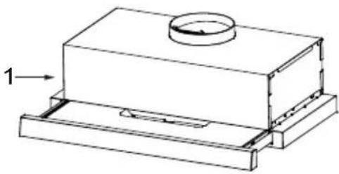
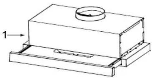
| 1 | 1 | Hood Body, complete with: Controls, Light, Blower, Filter. |
| 2 | 2 | The Activated Charcoal filter (2 optional) |
| 3 | 4 | Screws 5 x 50 |
| 4 | 4 | Wall Plugs |
natural_image
Technical line drawing of a mechanical component with a circular top and base (no text or symbols)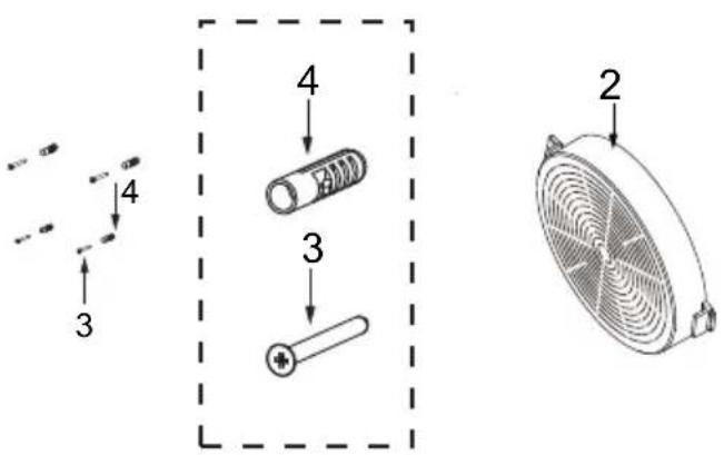
unit: mm
METHOD 1
natural_image
Technical line drawing of a mechanical assembly with two components and mounting brackets (no text or symbols)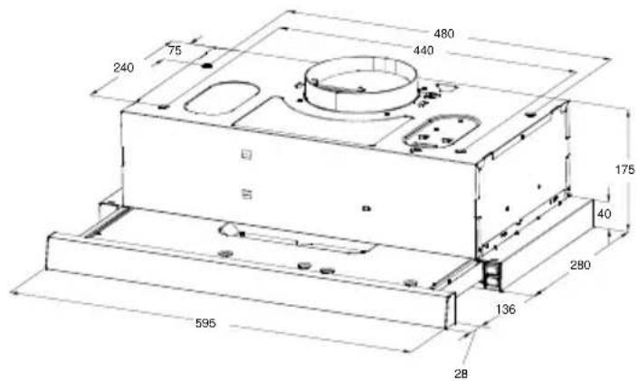
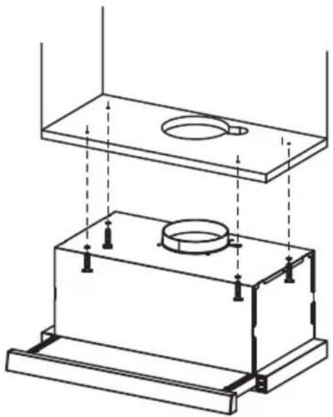
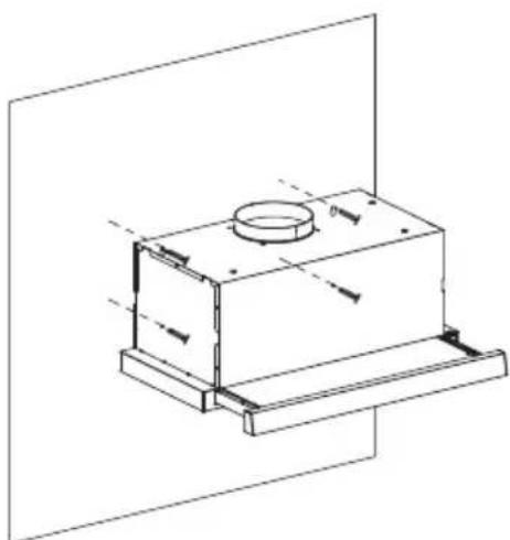
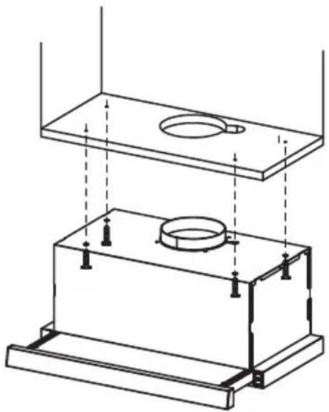
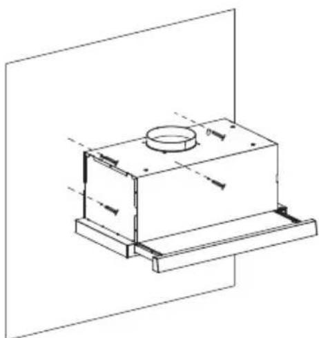
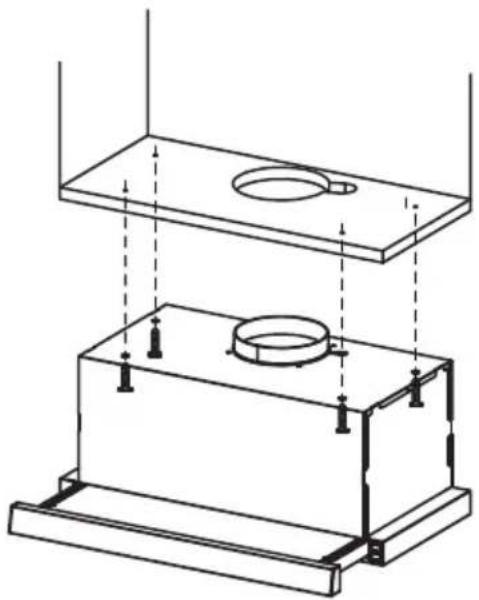
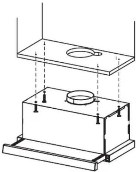
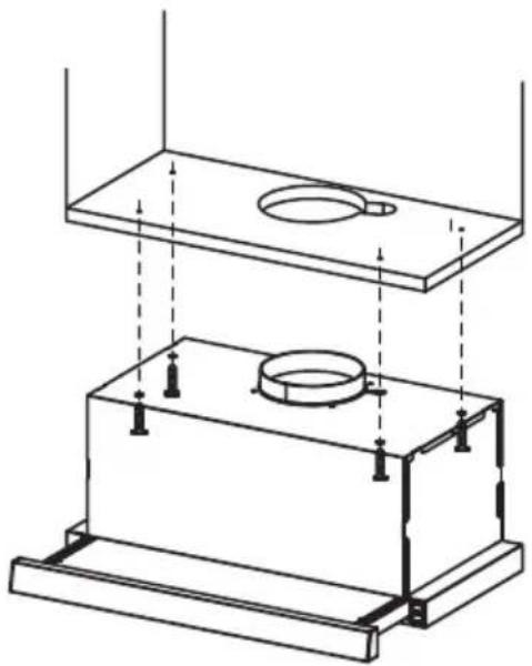
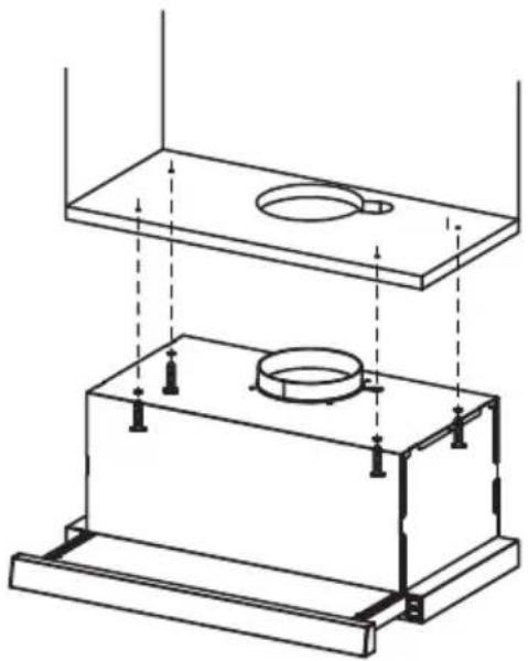
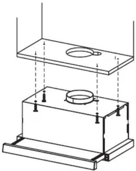
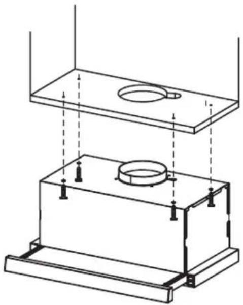
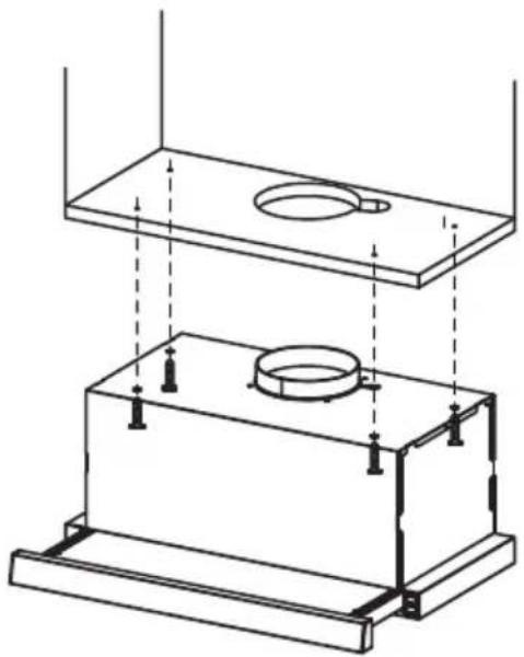
- According to the figure, make sure the position of hood in the cabinet. The wood strips should be line up with the 4 keyholes slots on the top of the range hood. On the cabinet, install 4 screws (supplied) according to the relative position of 4 key holes on the bottom of hood. The extent of screwing should be convenience to the next installation.
- Hang the hood and let it's 4 key holes aim at screws, the 4 screws should be in the narrow parts of key holes. Screws should be fasten firmly, make sure that the installation between the hood and cabinet is enough fasten.
- Install screws in the security holes, in case of front and back moving of hood, so that the using is safer.

Information
When cutting or drilling into wall or ceiling, do not damage electrical wiring or other hidden utilities.
METHOD 2
natural_image
Technical line drawing of a mechanical housing or enclosure with mounting base and cylindrical top (no text or symbols)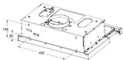
z In the installation surface in cabinet don't adapt to install the cooker hood, then as per fig, fix the position of cooker hood on the wall.
z ☐ On the wall, install 2 screws ( supplied ) according to the relative position of 2 key holes on the back of hood.
z The extent of screwing should be convenience to the next installation.
z Also install screws in the security holes, in case of front and back moving of hood, so that the using is safer.
Installation of hoods built in combi cabinets is the same as previous method.

Information
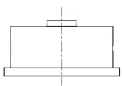
Congratulations on the purchase our cooker hood which is designed to include many superior features that permit you the fullest expression of your living. Before installing and/or using the cooker hood carefully read all the instruction.
natural_image
Pure mechanical part diagram showing a rectangular block with a central rectangular block and dashed centerline (no text or symbols)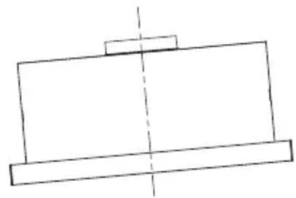
natural_image
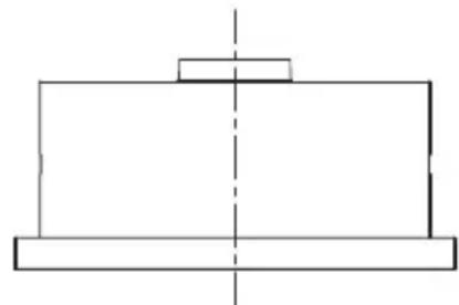
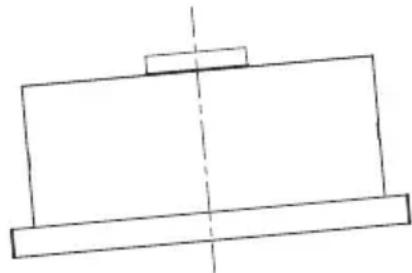
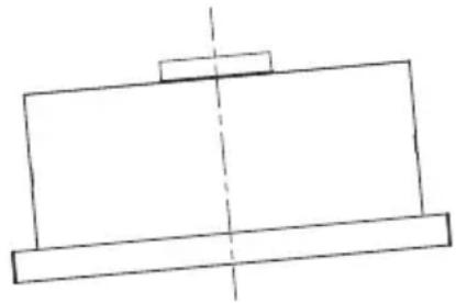
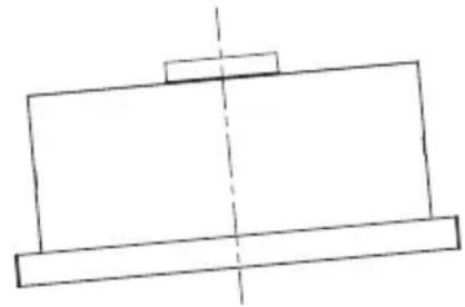
Simple line drawing of a rectangular frame with a vertical dashed centerline (no text or symbols)Right Wrong

Information
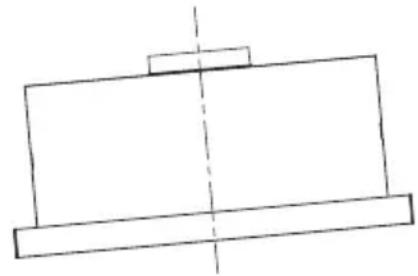
The cooker hood must not be installed and connected to flues where other appliances are installed and which run off other energy supplied different to electricity(water heater boiled cookers(range/agas)etc.).
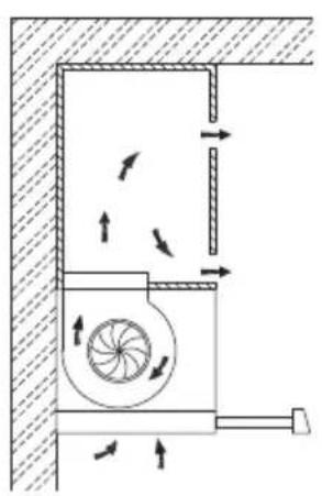
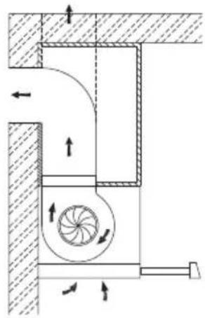
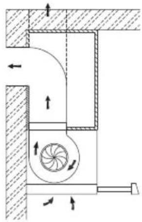
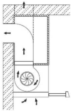
Here two venting modes, extraction-air mode and recirculation mode, before installing should be select one of them.
Extraction-air mode, the air is discharged out of the house by a pipe.
Recirculation mode, the air is purified and discharged into the house.
natural_image
Technical diagram of a mechanical ventilation system with airflow arrows and fan components (no text or labels)Recirculation mode Extraction-air mode
natural_image
Cross-sectional diagram of a mechanical ventilation system with fan and airflow indicators (no text or labels)Information
Recirculation mode, the cabinet needs an air vent.
Recirculation mode, always be with activated carbon filter.
Recirculation mode, when activated carbon filter attached, the suction power will be lowered.
Operation
Check beforehand
Check the safe condition of the appliance:
- Check whether there are visible defects.
- Check that all parts of the appliance have been securely fitted.
● In the right part of the cooker hood. (For some models)
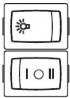
● There are 2 speeds for the motor and on off switch of the lamp.
- Locker switch for operation.
Light Operation
• [ ]=Off
- [☀] = On
Motor Operation
• [○]=Off
• [ ]=Low Power Setting
• [ II]=High Power Setting
natural_image
Two identical rectangular electronic devices with icons, no text or symbols presentGREASE FILTERS
CLEANING METAL SELF-SUPPORTING GREASE FILTERS
- The filters must be cleaned every 2 months of operation, or more frequently for particularly heavy usage, and can be washed in a dishwasher.
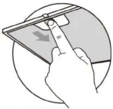
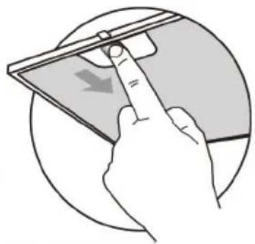
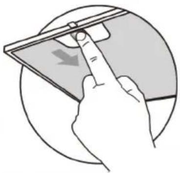
● Pull the comfort panels to open them. - Remove the filters one by one pushing them towards the back side of the hood unit and simultaneously pulling downwards.
- Any kind of bending of the filters has to be avoided when washing them. Before fitting them again into the hood make sure that they are completely dry. (The color of the filter surface may change throughout the time but this has no influence to the filter efficiency).
- When fitting the filters into the hood pay attention that they are mounted in correct position the handle facing outwards.
- Close the comfort panel.
natural_image
Illustration of a hand inserting a device into a tablet (no text or symbols visible)ACTIVATED CHARCOAL FILTER (RECIRCULATION VERSION)
REPLACING THE ACTIVATED CHARCOAL FILTER
These filters are not washable and cannot be regenerated, and must be replaced approximately every 4 months of operation, or more frequently with heavy usage.
REPLACING THE ACTIVATED CHARCOAL FILTER
- Remove the metal grease filters
- Remove the saturated activated charcoal filter.
● Fit the new filters. - Replace the metal grease filters.
natural_image
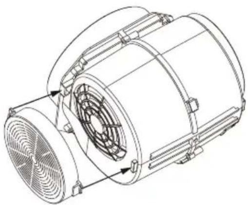
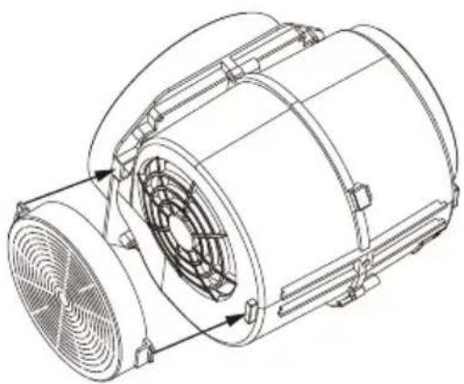
Technical line drawing of a mechanical fan assembly (no text or symbols)Changing the light
Lightning inside the appliance is provided by a 1.5W LED light.
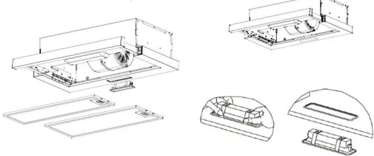
To replace the LED light, proceed as follows:
- Disconnect the appliance from the mains or switch off the circuit breaker.
- Remove the metal filters (see Cleaning and Replacing Filters).
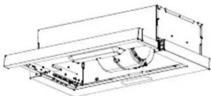
- Remove the light by levering its fitting from the hood body(this may require pressure or force to be applied) and disconnect the connector of the light.
- Replace the light with a new one of the same type, making sure that you connect the light with the light cable correctly.
- Install the metal filter back in place.
natural_image
Technical line drawing of a mechanical assembly with no visible text or symbols| Max power | Voltage Picture | Lamp Cap ILCOS D code | |||
| Self-ballasted LED modules | 1.5W 220V-240V | 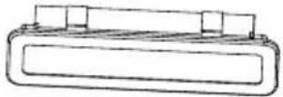 Square/Diameter:33.2mmx120mm Square/Diameter:33.2mmx120mm | / | DBS-1.5-H-33.2/120 | |
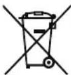
DISPOSAL OF OLD ELECTRICAL APPLIANCES
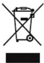
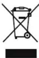
The European directive 2012/19/EU on Waste Electrical and Electronic Equipment (WEEE), requires that old household electrical appliances must not be disposed of in the normal unsorted municipal waste stream. Old appliances must be collected separately in order to optimize the recovery and recycling of the materials they contain, and reduce the impact on human health and the environment.
The crossed out "wheeled bin" symbol on the product reminds you of your obligation, that when you dispose of the appliance, it must be separately collected.
Consumers should contact their local authority or retailer for information concerning the correct disposal of their old appliance.
| Fault | Cause | Solution |
| Light on, but motor does not work | The blades are blocked. | |
| The capacitor is damaged. | Replace capacitor. | |
| The motor is damaged. | Replace motor. | |
| The internal wiring of motor is cut off/disconnected. An unpleasant smell may be produced. | Replace motor. | |
| Both light and motor do not work | Apart from the above mentioned, check the following: | |
| Light damaged. | Replace lights. | |
| Power cord loose. | Connect the wires as per the electric diagram. | |
| Oil leakage | Outlet and the air ventilation entrance are not tightly sealed. | Take down the outlet and seal with glue. |
| Leakage from the connection of U-shaped section and cover. | Take U-shaped section down and seal with soap or paint. | |
| Vibration | The blade, if damaged, can cause vibrating. | Replace the blade. |
| The motor is not tightly fastened. | Fasten the motor tightly. | |
| The cooker hood is not tightly fixed. | Fixed the cooker hood tightly. | |
| Insufficient suction | The distance between the cooker hood and the cooker top is too large. | Readjust the distance. |
| Too much ventilation from open doors or windows. | Choose a new place to install the appliance or close some doors / windows. | |
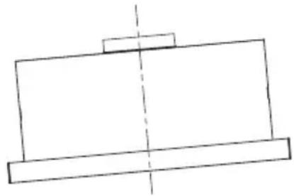
| The machine inclines | The fixing screws are not tight enough. | Tighten the fixing screw and make it horizontal. |
| The hanging screws are not tight enough | Tighten the hanging screw and make it horizontal. | |

PIO6L03IX
PIO6L03W
natural_image
Technical line drawing of a rectangular housing with a circular top component and base support (no text or symbols)ASPIRATOR
UPUTSTVO ZA UPOTREBU
Pre upotrebe proizvoda pažljivo pročitajte uputstvo
Slike u ovom uputstvu su samo za referencu, stvarni izgled proizvoda ima prednost.

natural_image
Simple line drawing of a lamp emitting steam from a heated source (no text or symbols)UPOTREBA
ODRŽAVANJE
- Aspirator i filter treba redovno čistiti prema uputstvima.
- Isključite utikač uređaja iz električne utičnice pre čišćenja uređaja.
- Očistite haubu aspiratora koristeći vlažnu krpu i neutralni tečni deterdžent.
- Uređaj koristi maksimalno 4 grejne zone na šporetu.
natural_image
Simple line drawing of a house with a stove and a chimney, no text or symbols present
Simbol na ambalaži ukazuje na to da se ovaj proizvod ne sme tretirati kao kućni otpad. Umesto toga, treba ga predati odgovarajućem sakupljalištu za recikliranje električne i elektronske opreme. Osiguravajući pravilno odlaganje ovog proizvoda, pomažete sprečavanju potencijalno negativnih posledica po životnu sredinu i ljudsko zdravlje, koje bi inače mogle nastati usled neadekvatnog rukovanja otpadom ovog proizvoda. Za detaljnije informacije o reciklaži ovog proizvoda, obratite se lokalnoj gradskoj upravi, službi za odlaganje kućnog otpada ili prodavnici u kojoj ste kupili proizvod.
GLAVNI PARAMETRI
Napon i frekvencija: 220-240V\~ 50Hz
Ulazna snaga motora: 115W
U određenim okolnostima električni uređaj može biti opasan.
KOMPONENTE
| Br. Kol. Delovi proizvoda | ||
| 1 | 1 | Telo aspiratora, zajedno sa: kontrolama, svetlom, ventilatorom, filterom. |
| 2 | 2 | Aktivni ugljeni filter (2 optiona) |
| 3 | 4 | Vijci 5 x 50 |
| 4 | 4 | Tiplovi za zid |
natural_image
Technical line drawing of a mechanical component with a circular top and base, showing no text or symbols.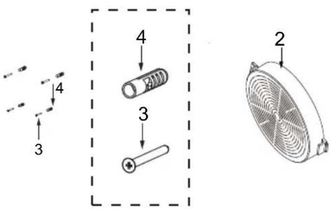
NAČIN 1
natural_image
Technical line drawing of a mechanical assembly with two components and mounting brackets (no text or symbols)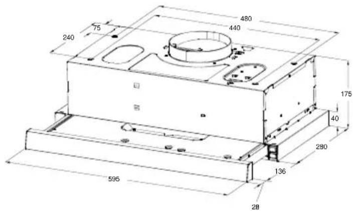
Kao na slici, obratite pažnju na poziciju aspiratora u elementu. Drvene trake treba poravnati sa 4 ključne rupe na vrhu aspiratora. Na elementu, postavite 4 vijka (isporučena) u skladu sa položajem 4 ključne rupe na dnu aspiratora. Navijanje vijaka treba da bude odgovarajuće za sledeću instalaciju.
- Okačite aspirator tako da njegove 4 ključne rupe budu usmerene prema vijcima, a 4 vijka treba da budu u uskim delovima ključnih rupa. Vijci treba da budu čvrsto zategnuti i vodite računa da je instalacija između aspiratora i elementa dovoljno čvrsta.
- Postavite vijke u sigurnosne rupe, radi sprečavanja pomeranja aspiratora napred i nazad, kako bi korišćenje bilo sigurnije.

Informacija
Prilikom sečenja ili bušenja zida ili plafona, pazite da ne oštetite električne instalacije ili druge skrivene delove.
NAČIN 2
natural_image
Technical line drawing of a mechanical housing or enclosure with mounting base and cylindrical top (no text or symbols)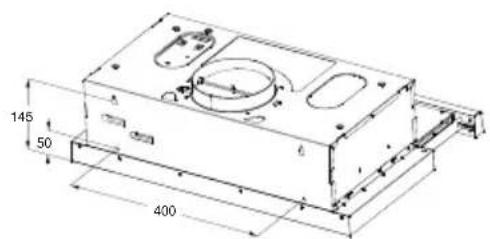
z ☐ Ukoliko kuhinjski element nije odgovarajući za montažu aspiratora, onda prekao na slici, postavite aspirator na zid.
z ☐ Postavite 2 vijka na zid (isporučena) u skladu sa položajem 2 ključne rupe na zadnjem delu aspiratora.
z ☐ Navijte vijke samo do položaja koji je odgovarajući za narednu insatalaciju.
z Takođe, postavite vijke u sigurnosne rupe, radi sprečavanja pomeranja aspiratora napred i nazad, kako bi korišćenje bilo sigurnije.
Instalacija ugradnih aspiratora u kombinovane elemente ista je kao u prethodno opisanom načinu.

Informacija
Čestitamo vam na kupovini našeg aspiratora koji je dizajniran sa mnogo superiornih funkcija koje vam olakšavaju život. Pre nego što instalirate i/ili koristite aspirator, pažljivo pročitajte sva uputstva.
natural_image
Pure mechanical part diagram showing a stepped base with a central vertical axis (no text or symbols)Ispravno
natural_image
Simple line drawing of a mechanical or architectural component with no text or symbolsPogrešno

Informacije
Aspirator se ne sme instalirati i povezivati sa dimnjacima gde su instalirani drugi uređaji i koji koriste drugačiji izvor energije od električne (bojleri na vodu, šporeti na plin i druge vrste goriva itd.).
Postoje dva režima ventilacije, režim izduvavanja vazduha i režim recirkulacije. Pre instalacije treba odabrati jedan od ova dva režima.
natural_image
Technical diagram of a mechanical ventilation system with airflow arrows and fan components (no text or labels)natural_image
Cross-sectional diagram of a mechanical ventilation system with airflow arrows and fan components (no text or labels)Informacije
natural_image
Two identical rectangular electronic devices with icons, no text or symbols presentFILTERI ZA MASNOĆU
ČIŠĆENJE METALNIH SAMONOSEĆIH FILTERA ZA MASNOĆU
- Filtere treba čistiti svaka 2 meseca rada, ili češće ukoliko je upotreba posebno intenzivna, i mogu se prati u mašini za pranje sudova.
● Povucite panel da biste otvorili. - Izvucite filtere jedan po jedan gurajući ih prema zadnjem delu aspiratora i istovremeno ih povlačeći nadole.
- Prilikom pranja, izbegavajte savijanje filtera. Pre nego što ih ponovo postavite u aspirator, uverite se da su potpuno suvi. (Boja površine filtera može se promeniti tokom vremena, ali to ne utiče na efikasnost filtera).
- Prilikom postavljanja filtera u aspirator, obratite pažnju da su montirani u pravilnom položaju, sa ručkom okrenutom prema spolja.
- Zatvorite panel.
natural_image
Illustration of a hand inserting a device into a tablet, showing a finger pointing at the screen (no text or symbols present)AKTIVNI UGLJENI FILTER (VERZIJA SA RECIRKULACIJOM)
ZAMENA AKTIVNOG UGLJENOG FILTRA
natural_image
Technical line drawing of a mechanical fan assembly (no text or symbols)Zamena sijalice
Unutar uređaja osvetljenje je LED svetlo snage 1,5W.
natural_image
Technical line drawings of a device interior showing exploded and assembled views (no text or symbols)| Maks. snaga | Napon | Slika | Pokopac svetla | ILCOS D kod | |
| LED moduli sa sopstvenim balastom | 1.5W 220V-240V | 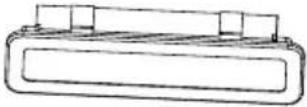 Kvadrat/prečnik:33.2mmx120mm Kvadrat/prečnik:33.2mmx120mm | / | DBS-1.5-H-33.2/120 | |
ODLAGANJE ELEKTRIČNIH UREĐAJA
natural_image
Technical line drawing of a rectangular housing with a circular top and base plate (no text or symbols)KUHINJSKA NAPA
NAVODILA ZA UPORABO
natural_image
Simple line drawing of a heating setup with a lamp, smoke, and control panel (no text or symbols)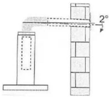
natural_image
Simple line drawing of a house with a stove and fire, no text or symbols presentNazivna napetost in frekvenca 220-240 V \~ 50/60 Hz
natural_image
Technical line drawing of a mechanical component with a circular top and base, showing a cross-section view (no text or symbols)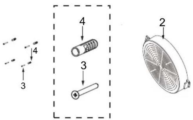
NAČIN 1
natural_image
Technical line drawing of a mechanical assembly with two components and mounting brackets (no text or symbols)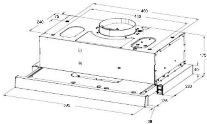
natural_image
Technical line drawing of a mechanical housing or enclosure with mounting base and cylindrical top (no text or symbols)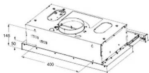
natural_image
Pure mechanical assembly diagram showing a rectangular block with a central vertical shaft and base, no text or symbols present.Prav
natural_image
Simple line drawing of a rectangular object with a vertical axis and horizontal base (no text or symbols)Napačno

Informacija
natural_image
Technical diagram of a mechanical ventilation system with airflow arrows and fan components (no text or labels)Način recirkulacije
natural_image
Cross-sectional diagram of a mechanical ventilation system with fan and airflow indicators (no text or labels)natural_image
Two identical rectangular electronic devices with icons, no text or symbols presentMAŠČOBNI FILTRI
ČIŠČENJE KOVINSKIH MAŠČOBNIH FILTROV
natural_image
Illustration of a hand inserting a device into a tablet (no text or symbols visible)AKTIVIRANI OGLENI FILTER (RAZLIČICA S PONOVNIM KROŽENJEM)
ZAMENJAVA FILTRA Z AKTIVNIM OGLJEM
natural_image
Technical line drawing of a mechanical fan assembly (no text or symbols)natural_image
Technical line drawing of a mechanical assembly with no visible text or symbols| Najv. moč | Napetost | Slika | Pokrov svetilke | Koda ILCOS D | |
| LED moduli z ločenim balastom | 1.5W 220V-240V |  Kvadrat/premer:33.2mmx120mm Kvadrat/premer:33.2mmx120mm | / | DBS-1.5-H-33.2/120 | |
RAVNANJE Z ODSLUŽENIMI ELEKTRIČNIMI NAPRAVAMI

natural_image
Technical line drawing of a rectangular housing with a circular top component and base support (no text or symbols)KUHINJSKA NAPA
UPUTE ZA UPORABU
Pažljivo pročitajte ove upute prije uporabe.
natural_image
Simple line drawing of a laboratory setup with a conical flask, thermometer, and gas stove (no text or symbols)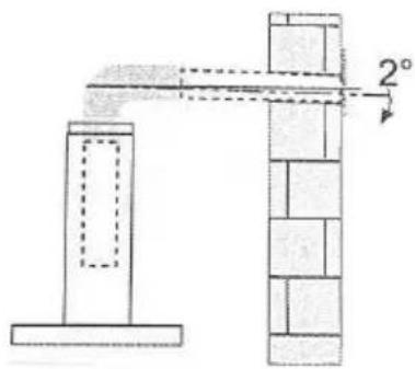
natural_image
Simple line drawing of a house with a stove and fire, no text or symbols presentnatural_image
Technical line drawing of a rectangular mechanical component with a circular top and base, showing a cross-section view (no text or symbols)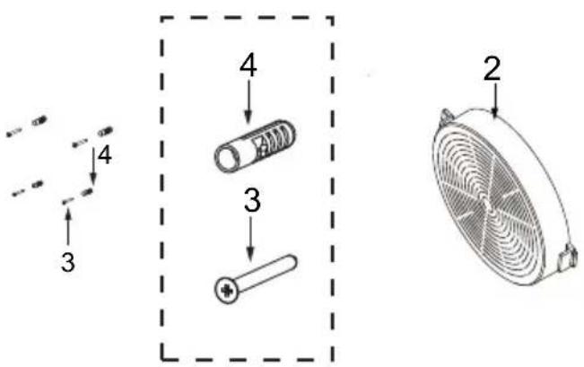
NAČIN 1
natural_image
Technical line drawing of a mechanical assembly with two components and mounting brackets (no text or symbols)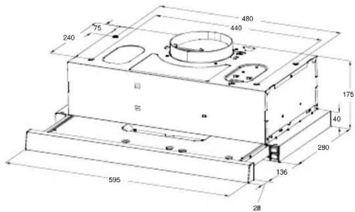
natural_image
Technical line drawing of a mechanical housing or enclosure with mounting base and cylindrical top (no text or symbols)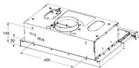
natural_image
Pure mechanical assembly diagram showing a central shaft and two plates (no text or symbols)Ispravno
natural_image
Simple line drawing of a rectangular frame with a vertical centerline and a small rectangle on top (no text or symbols)Pogrešno

Informacija
natural_image
Technical diagram of a mechanical ventilation system with airflow arrows and fan components (no text or labels)Način recilkulacije
natural_image
Cross-sectional diagram of a mechanical ventilation system with fan and airflow indicators (no text or labels)Način ekstrakcije zraka
Informacija
Način recirkulacije, kabinet treba ventilacijski otvor.
natural_image
Two identical rectangular electronic devices with icons, no text or symbols presentFILTERI ZA MASNOĆU
ČIŠĆENJE METALNIH SAMONOSEĆIH FILTERA ZA MASNOĆU
- Filtre je potrebno čistiti svaka 2 mjeseca rada, ili češće za posebno kod učestale uporabe, i mogu se prati u perilici posuđa.
● Povucite panele da ih otvorite. - Uklonite filtere jedan po jedan gurajući ih prema stražnjoj strani nape i istovremeno povlačeći prema dolje.
- Prilikom pranja filtara treba izbjegavati bilo kakvo savijanje. Prije ponovnog postavljanja u napu provjerite jesu li potpuno suhe. (Boja površine filtera može se mijenjati tijekom vremena, ali to nema utjecaja na učinkovitost filtera).
- Prilikom postavljanja filtara u napu pazite da su postavljeni u ispravnom položaju, s ručkom okrenutom prema van.
- Zatvorite panele.
natural_image
Illustration of a hand holding a tablet device with a download arrow (no text or symbols)FILTAR S AKTIVNIM UGLJENOM (VERZIJA S CIRKULIRANJEM ZRAKA)
ZAMJENA FILTRA S AKTIVNIM UGLJENOM
Ovi filtri se ne mogu prati i ne mogu se regenerirati, te se moraju zamijeniti otprilike svaka 4 mjeseca rada ili češće kod veće upotrebe.
ZAMJENA FILTRA S AKTIVNIM UGLJENOM
- Uklonite metalne filtere za masnoću
- Uklonite zasićeni filtar s aktivnim ugljenom.
● Postavite nove filtere. - Vratite na mjesto metalne filtere za masnoću.
natural_image
Technical line drawing of a mechanical fan assembly (no text or symbols)Mijenjanje svjetla
natural_image
Exploded view diagram of a mechanical assembly showing internal components and housing (no text or labels)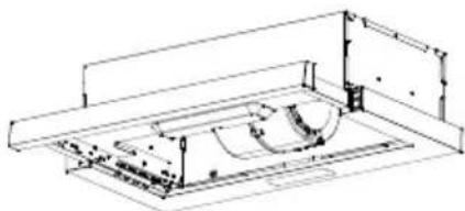
natural_image
Technical line drawing of a mechanical assembly with no visible text or symbols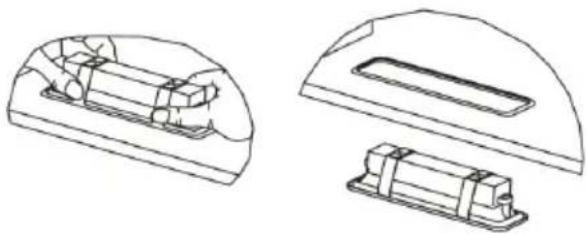
natural_image
Technical line drawings of two mechanical components with internal compartments (no text or symbols)| Maks. snaga | Napon | Slika | Pokopac svjetla | ILCOS D kod | |
| LED moduli s vlastitim balastom | 1.5W | 220V-240V | 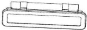 Kvadrat/promjer:33,2mmx120mm Kvadrat/promjer:33,2mmx120mm | / | DBS-1.5-H-33.2/120 |
ODLAGANJE STARIH ELEKTRIČNIH UREĐAJA
Europska Direktiva 2012/19/EU o otpadnoj električnoj i elektroničkoj opremi (WEEE) zahtijeva da se stari električni kućanski uređaji ne smiju odlagati u uobičajeni nerazvrstani gradski otpad. Stari uređaji moraju se prikupljati odvojeno kako bi se optimizirala oporaba i recikliranje materijala koje sadrže i smanjio utjecaj na ljudsko zdravlje i okoliš. Simbol prekrižene "kante za otpad" na proizvodu podsjeća vas na vašu obvezu da kada želite zbrinuti uređaj, mora se skupljati odvojeno. Potrošači bi se trebali obratiti svojim lokalnim vlastima ili trgovcu za informacije o pravilnom odlaganju svojih starih uređaja.
natural_image
Technical line drawing of a rectangular housing with a circular top component and base support (no text or symbols)АСПИРАТОР
natural_image
Simple line drawing of a laboratory setup with a conical flask, thermometer, and gas stove (no text or symbols)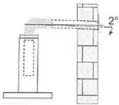
natural_image
Simple line drawing of a house with a stove and fire, no text or symbols presentНоминален напон и фреквенција 220-240V\~ 50/60Hz
Влезна мокност на моторот: 115 W
natural_image
Technical line drawing of a mechanical component with a circular top and base, showing no text or symbols.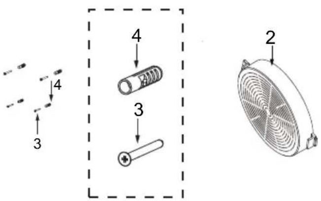
МЕТОД 1
natural_image
Technical line drawing of a mechanical assembly with two components and mounting brackets (no text or symbols)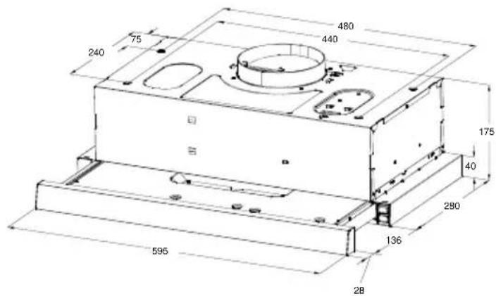
natural_image
Technical line drawing of a mechanical housing or enclosure with mounting base and cylindrical top (no text or symbols)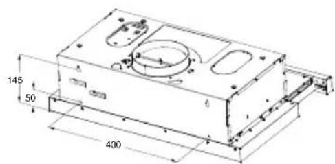
natural_image
Pure mechanical diagram showing a rectangular block with a central vertical bar and base, no text or symbols present.Точно
natural_image
Simple line drawing of a rectangular frame with a vertical centerline and a small rectangle on top (no text or symbols)Погрешно

Информација
natural_image
Technical diagram of a mechanical ventilation system with airflow arrows and fan components (no text or labels)natural_image
Cross-sectional diagram of a mechanical ventilation system with fan and airflow indicators (no text or labels)natural_image
Two identical rectangular panels with sun icon and two circular symbols inside, no text or labels presentФИЛТРИ ЗА МАСНОТИИ
natural_image
Illustration of a hand holding a tablet device with a download arrow (no text or symbols)ФИЛТЕР СО АКТИВНИОТ ЈАГЛЕН (ВЕРЗИЈА СО КРУЖЕЊЕ)
ЗАМЕНА НА ФИЛТЕРОТ СО АКТИВЕН ЈАГЛЕН
natural_image
Technical line drawing of a mechanical fan assembly (no text or symbols)natural_image
Technical line drawing of a rectangular housing with a circular top and base plate (no text or symbols)EXAUSTOR DE COZINHA
MANUAL DE INSTRUÇÕES
natural_image
Illustration of a laboratory setup with a conical flask, heating a lamp, and a control panel (no text or symbols)UTILIZAÇÃO
natural_image
Simple line drawing of a house with a chimney and a cooking pot, emitting steam from a chimney (no text or symbols)
natural_image
Technical line drawing of a mechanical component with a circular top and base, showing a cross-section view (no text or symbols)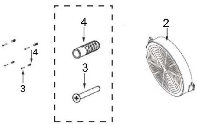
MÉTODO 1
natural_image
Technical line drawing of a mechanical assembly with two components and mounting brackets (no text or symbols)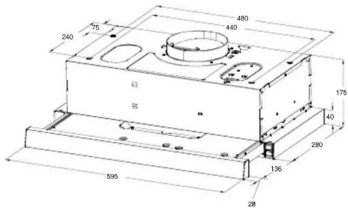
natural_image
Technical line drawing of a mechanical housing or enclosure with mounting base and cylindrical top (no text or symbols)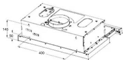
natural_image
Pure mechanical diagram showing a rectangular block with a central vertical dashed line and a small rectangular block above it (no text or symbols)Correcto
natural_image
Simple line drawing of a rectangular object with a vertical axis and horizontal base (no text or symbols)Errado

Informações
natural_image
Technical diagram of a mechanical ventilation system with airflow arrows and fan components (no text or labels)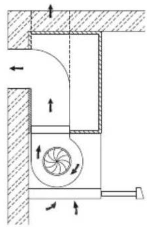
natural_image
Cross-sectional diagram of a mechanical ventilation system with fan and vent components (no text or labels)natural_image
Two identical rectangular panels with sun icon and two circular symbols inside, no text or labels presentFILTROS DE GORDURA
LIMPEZA DOS FILTROS DE GORDURA METÁLICOS DE AUTOSUPORTE
natural_image
Illustration of a hand holding a tablet with a finger pointing at it, showing a download arrow (no text or symbols present)natural_image
Technical line drawing of a mechanical fan assembly (no text or symbols)natural_image
Technical line drawing of a rectangular housing with a circular top component and base support (no text or symbols)АСПИРАТОР
РЪКОВОДСТВО ЗА УПОТРЕБА
natural_image
Simple line drawing of a laboratory setup with a conical flask, heating a test tube, and a control panel (no text or symbols)УПОТРЕБА
natural_image
Simple line drawing of a house with a pot and fire, no text or symbols present
natural_image
Technical line drawing of a mechanical component with a circular top and base (no text or symbols)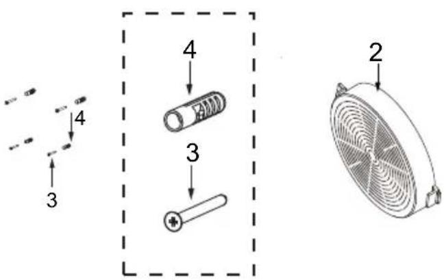
единица: mm
МЕТОД 1
natural_image
Technical line drawing of a mechanical assembly with two components and mounting brackets (no text or symbols)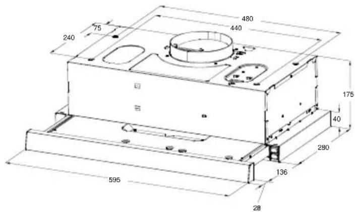
natural_image
Technical line drawing of a mechanical housing or enclosure with mounting base and cylindrical top (no text or symbols)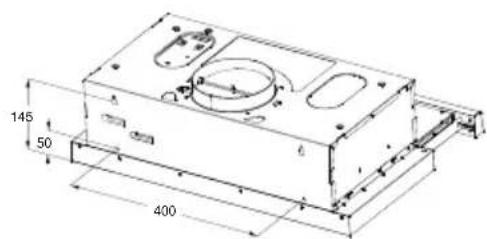
natural_image
Pure technical line drawing of a mechanical part with no text or symbols
natural_image
Simple line drawing of a rectangular frame with a vertical axis and a small rectangle on top (no text or symbols)Правилно Неправилно

Информация
natural_image
Technical diagram of a mechanical ventilation system with airflow arrows and fan components (no text or labels)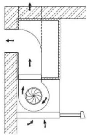
natural_image
Technical diagram of a mechanical ventilation system with airflow arrows and component labels (no readable text or symbols)natural_image
Two rectangular electronic devices with icons, no text or symbols presentФИЛТРИ ЗА МАЗНИНА
ПОЧИСТВАНЕ НА МЕТАЛНИТЕ ФИЛТРИ ЗА МАЗНИНА
natural_image
Illustration of a hand inserting a tablet into a device (no text or symbols visible)natural_image
Technical line drawing of a mechanical fan assembly (no text or symbols)СМЯНА НА ЛАМПА
natural_image
Technical line drawings of a device interior showing internal components and exploded views (no text or symbols)natural_image
Technical line drawing of a rectangular housing with a circular top component and base support (no text or symbols)ΑΠΟΡΡΟΦΗΤΗΡΑΣ
ΕΓΧΕΙΡΙΔΙΟ ΧΡΗΣΗΣ
natural_image
Simple line drawing of a house with a stove and a person standing on a platform, no text or symbols present.
natural_image
Technical line drawing of a mechanical component with a circular top and base, showing a cross-section view (no text or symbols)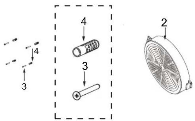
ΜΕΘΟΔΟΣ 1
natural_image
Technical line drawing of a mechanical assembly with two components and mounting brackets (no text or symbols)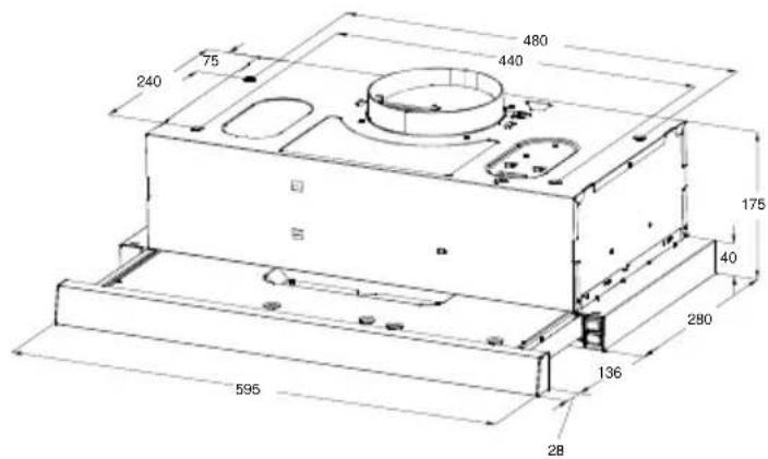
natural_image
Technical line drawing of a mechanical housing or enclosure with mounting base and cylindrical top (no text or symbols)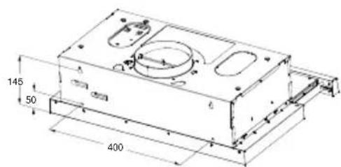
natural_image
Pure mechanical diagram showing a rectangular block with a central vertical bar and base, no text or symbols present.Σωστό
natural_image
Simple line drawing of a rectangular frame with a vertical centerline and horizontal base (no text or symbols)Λάθος

Πληροφορίες
natural_image
Technical diagram of a mechanical ventilation system with airflow arrows and fan components (no text or labels)natural_image
Technical diagram of a mechanical ventilation system with airflow arrows and component layout (no text or labels)natural_image
Two identical rectangular icons with sun, circle, and double vertical bars inside, no text or symbols present.ΦΙΛΤΡΑ ΛΙΠΟΥΣ
natural_image
Illustration of a hand holding a tablet with a finger pointing at it, showing a download icon (no text or symbols present)natural_image
Technical line drawing of a mechanical fan assembly (no text or symbols)ΑΝΤΙΚΑΤΑΣΤΑΣΗ ΦΩΤΟΣ
Αλλαγή φωτός
natural_image
Technical line drawings of an electronic device interior showing internal components and exploded views (no text or labels)natural_image
Technical line drawing of a rectangular housing with a circular top component and base support (no text or symbols)CAMPANA EXTRACTORA
natural_image
Simple line drawing of a laboratory setup with a conical flask, thermometer, and gas stove (no text or symbols)USO
natural_image
Simple line drawing of a house with a stove and fire, no text or symbols presentnatural_image
Technical line drawing of a mechanical component with a circular top and base, showing a cross-section view (no text or symbols)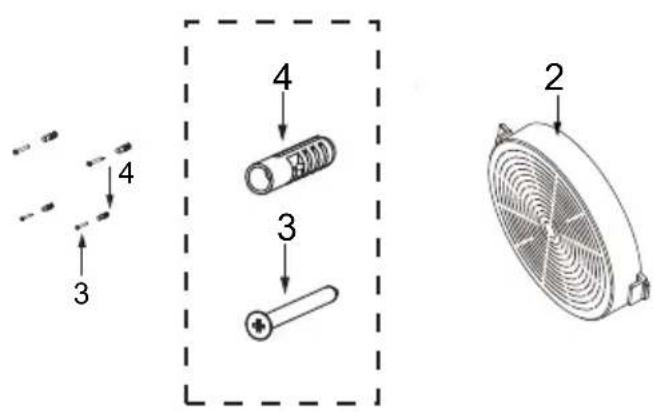
METODO 1
natural_image
Technical line drawing of a mechanical assembly with two components and mounting brackets (no text or symbols)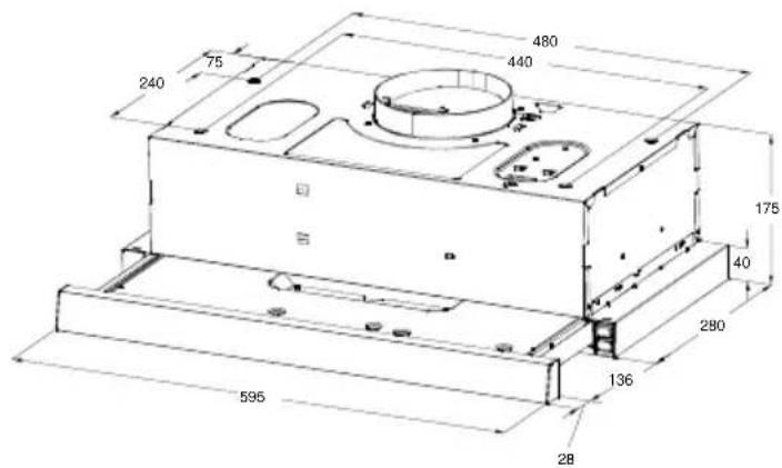
natural_image
Technical line drawing of a mechanical housing or enclosure with mounting base and cylindrical top (no text or symbols)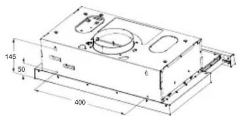
natural_image
Pure mechanical diagram showing a rectangular block with a central vertical bar and base, no text or symbols present.Correcto
natural_image
Simple line drawing of a rectangular frame with a vertical centerline and a small rectangle on top (no text or symbols)Incorrecto

Información
natural_image
Technical diagram of a mechanical ventilation system with airflow arrows and fan components (no text or labels)natural_image
Cross-sectional diagram of a mechanical ventilation system with fan and airflow indicators (no text or labels)natural_image
Two identical rectangular electronic devices with icons, no text or symbols presentFILTROS DE GRASA
LIMPIEZA DE FILTROS DE GRASA METÁLICOS AUTOSOPORTANTES.
natural_image
Illustration of a hand inserting a tablet into a device, showing a download icon (no text or symbols present)natural_image
Technical line drawing of a mechanical fan assembly (no text or symbols)REEMPLAZO DE LUZ
Cambiar la luz
natural_image
Technical line drawing of an open refrigerator internal compartments and casing (no text or labels)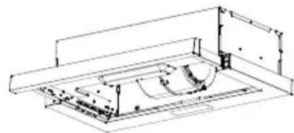
natural_image
Technical line drawing of a mechanical assembly or enclosure with no visible text or symbols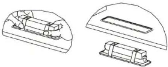
natural_image
Technical line drawings of two mechanical components with internal cavities (no text or symbols)- COOKER HOOD
- INSTRUCT ON MANUALI
- INSTALLATION
- USE
- MAINTENANCE
- COMPONENTS
- METHOD 1
- Information
- METHOD 2
- Right Wrong
- Operation
- Light Operation
- Motor Operation
- GREASE FILTERS
- ACTIVATED CHARCOAL FILTER (RECIRCULATION VERSION)
- REPLACING THE ACTIVATED CHARCOAL FILTER
- Changing the light
- To replace the LED light, proceed as follows:
- DISPOSAL OF OLD ELECTRICAL APPLIANCES
- ASPIRATOR
- UPUTSTVO ZA UPOTREBU
- UPOTREBA
- ODRŽAVANJE
- GLAVNI PARAMETRI
- KOMPONENTE
- NAČIN 1
- Informacija
- NAČIN 2
- Informacije
- FILTERI ZA MASNOĆU
- AKTIVNI UGLJENI FILTER (VERZIJA SA RECIRKULACIJOM)
- Zamena sijalice
- ODLAGANJE ELEKTRIČNIH UREĐAJA
- NAVODILA ZA UPORABO
- MAŠČOBNI FILTRI
- AKTIVIRANI OGLENI FILTER (RAZLIČICA S PONOVNIM KROŽENJEM)
- RAVNANJE Z ODSLUŽENIMI ELEKTRIČNIMI NAPRAVAMI
- KUHINJSKA NAPA
- UPUTE ZA UPORABU
- FILTAR S AKTIVNIM UGLJENOM (VERZIJA S CIRKULIRANJEM ZRAKA)
- ZAMJENA FILTRA S AKTIVNIM UGLJENOM
- Mijenjanje svjetla
- ODLAGANJE STARIH ELEKTRIČNIH UREĐAJA
- МЕТОД 1
- Информација
- ФИЛТРИ ЗА МАСНОТИИ
- ФИЛТЕР СО АКТИВНИОТ ЈАГЛЕН (ВЕРЗИЈА СО КРУЖЕЊЕ)
- MANUAL DE INSTRUÇÕES
- UTILIZAÇÃO
- MÉTODO 1
- Informações
- FILTROS DE GORDURA
- РЪКОВОДСТВО ЗА УПОТРЕБА
- УПОТРЕБА
- Правилно Неправилно
- Информация
- ФИЛТРИ ЗА МАЗНИНА
- СМЯНА НА ЛАМПА
- ΕΓΧΕΙΡΙΔΙΟ ΧΡΗΣΗΣ
- ΜΕΘΟΔΟΣ 1
- Πληροφορίες
- ΦΙΛΤΡΑ ΛΙΠΟΥΣ
- ΑΝΤΙΚΑΤΑΣΤΑΣΗ ΦΩΤΟΣ
- Αλλαγή φωτός
- CAMPANA EXTRACTORA
- USO
- METODO 1
- Información
- FILTROS DE GRASA
- REEMPLAZO DE LUZ
- Cambiar la luz
Brand : VOX
Model : PIO6L03IX
Category : Range hood