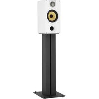
686 S2 - Loudspeaker B&W - Free user manual and instructions
Find the device manual for free 686 S2 B&W in PDF.


| Brand | B&W (Bowers & Wilkins) |
| Model | 686 S2 |
| Category | Bookshelf speaker |
| Product type | Passive speaker |
| Dimensions (approx.) | Not specified in the manual – typically 30 x 18 x 25 cm (H x W x D) |
| Weight (approx.) | Approximately 5.5 kg each |
| Power | Passive – requires an external amplifier |
| Impedance | Not specified – standard 8 Ω |
| Connectors | 2 pairs of terminals (bi-wiring possible) |
| Wall mounting | Yes, with keyhole bracket or ball joint mount (not supplied) |
| Application | Stereo or Home Cinema |
| Bass adjustment | Foam plugs supplied for attenuation |
| Break-in | 15 hours of normal use for mechanical components |
| Maintenance | Dusting, water and mild soap, avoid abrasive products |
| Safety | Keep away from devices sensitive to magnetic fields (≥50 cm) |
| Included parts | 2 foam plugs, 8 self-adhesive feet, 4 self-adhesive spacers |
| General information | Compliant with RoHS, REACH, WEEE |
Frequently Asked Questions - 686 S2 B&W
User questions about 686 S2 B&W
0 question about this device. Answer the ones you know or ask your own.
Ask a new question about this device
Download the instructions for your Loudspeaker in PDF format for free! Find your manual 686 S2 - B&W and take your electronic device back in hand. On this page are published all the documents necessary for the use of your device. 686 S2 by B&W.
USER MANUAL 686 S2 B&W
Welcome and thank you for choosing Bowers & Wilkins.
Our founder, John Bowers, believed that imaginative design, innovative engineering and advanced technology were keys that could unlock the enjoyment of audio in the home. His belief is one that we continue to share and inspires every product we design.
This is a high performance product that rewards thoughtful installation, so we suggest that you take some time to read this manual before you begin. Continue on page 4 →

- Unpacking
| 2 | |
| 8 | |
| 4 |
Carton Contents
Check in the carton for:
2 Two-part foam plugs
8 Self-adhesive plastic pads
4 Self-adhesive plastic stand-offs for 686 S2 only
Environmental Information
This product complies with international directives, including but not limited to:
i. the Restriction of Hazardous Substances (RoHS) in electrical and electronic equipment,
II. the Registration, Evaluation, Authorisation and restriction of CHemicals (REACH)
iii. the disposal of Waste Electrical and Electronic Equipment (WEEE).
Consult your local waste disposal authority for guidance on how properly to recycle or dispose of this product.
2. Positioning

natural_image
Mechanical assembly diagram showing a bracket with arrows indicating motion (no text or symbols)
natural_image
Technical line drawing of a mechanical assembly with a bolt and nut (no text or symbols)
natural_image
Mechanical assembly diagram showing a lever mechanism with arrows indicating motion direction (no text or symbols)Speaker Installation
The speaker is primarily designed to be mounted on a dedicated floor stand, but may be placed on a shelf, although this offers less flexibility to optimise the speaker's performance. In both cases, the tweeter should be approximately at ear height.
Note: If using a shelf, ensure that it is strong enough to properly support the weight and fit the 4 self-adhesive plastic feet to the underside of the speaker.
The 686 S2 speaker can be mounted on a wall using the bracket already attached to the back panel. The simplest method is to use a single screw into the wall and hook the bracket over it, in which case you should stick one of the supplied plastic stand-offs close to each of the bottom corners of the back panel to make the speaker sit parallel to the wall and avoid rattles. Make sure that the screw, any wall plug and the amount of insertion into the wall are sufficient to support the weight of the speaker. The slot in the bracket is 10mm wide, so you may use a woodscrew up to No. 24. We suggest a minimum size of No.14 or 6mm diameter.
If you wish to angle the speaker to the wall, you may use a third-party ball joint type bracket attached to the bracket already fixed to the speaker. You should ensure that the ball-joint bracket is capable of supporting the weight of the speaker. Your dealer or local Bowers & Wilkins distributor will be able to advise you on the selection of appropriate ball-joint brackets.
To attach a ball-joint style mount to a 686 S2 speaker, remove the bracket from the back panel of the speaker and securely attach the ball component through the central slot. Reattach the bracket and ball assembly to the back panel (see above).
Once the ball joint component is attached to the speaker, the assembly may be connected to the socket component attached to the wall. Ensure that the Manufacturer's instructions for attaching the bracket to the wall are followed correctly.
B&W Group Ltd. can accept no liability for any failure of wall fixings.
Speaker Positioning
Adjustment of speaker position following initial installation will probably further improve the sound quality and is usually worthwhile.
In either stereo or home theatre installations, try to ensure that the immediate surroundings of each speaker are similar in acoustic character. For example, if one speaker is adjacent to bare walls while the other is adjacent to soft furnishings and curtains, both the overall sound quality and the stereo image are likely to be compromised.
Conventional Stereo Systems
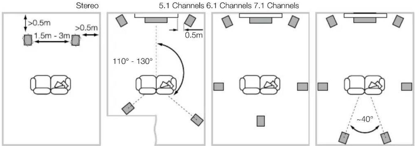
To begin with, the speakers should be positioned between 1.5m and 3m apart at two corners of an equilateral triangle completed by the listening area at the third corner. The speakers should be approximately 0.5m away from the back wall, and at least 0.5m away from any side walls (above).
Home Theatre Systems
If the speakers are to be used for the front channels in a home theatre system, they should be placed closer together than for 2-channel audio, because the surround channels tend to widen the image. Positioning the speakers within approximately 0.5m of the sides of the screen will also help keep the sound image in scale with the visual image. As with conventional stereo positioning, the speakers should ideally be at least 0.5m away from any side walls. If the speakers are preferred placed against the back wall and this location results in over emphasised bass, see the Fine Tuning section of this manual for information on using the foam plugs.
Stray Magnetic Fields
The speaker drive units create stray magnetic fields that extend beyond the boundaries of the cabinet. We recommend you keep magnetically sensitive articles (CRT television and computer screens, computer discs, audio and video tapes, swipe cards and the like) at least 0.5m from the speaker. LCD, OLED and plasma screens are not affected by magnetic fields.
- Connections

All connections should be made with the audio equipment switched off.
There are 2 linked pairs of terminals on the back of the speaker. For conventional connection (above left), the terminal links should remain in place (as delivered) and just one pair of terminals connected to the amplifier. For bi-wire connection (above right), the terminal links should be removed and each pair of terminals connected to the amplifier independently. Bi-wiring can improve the resolution of low-level detail.
Ensure that the positive terminals on the speaker (marked + and coloured red) are connected to the positive output terminal on the amplifier and the negative terminals on the speaker (marked – and coloured black) are connected to the negative output terminal on the amplifier. Incorrect connection can result in poor imaging and loss of bass.
Ask your dealer for advice when selecting speaker cable. Keep its total impedance below the maximum recommended in the speaker specification and use a low inductance cable to avoid attenuation of high frequencies.
- Fine Tuning

Before fine tuning, make sure that all the connections in the installation are correct and secure.
Moving the speakers further from the walls will generally reduce the volume of bass. Space behind the speakers will also help to create an aural impression of depth. Conversely, moving the speakers closer to the walls will increase the volume of bass. If you want to reduce the volume of bass without moving the speakers further from the wall, fit the foam plugs or, for less severe bass reduction, the foam rings in the port tubes (above).
If the bass seems uneven with frequency this will most probably be due to resonance modes in the listening room. Even small changes in the position of the speakers or the listening position can have a profound effect on how these resonances affect the sound. Try moving the listening position or locating the speakers along a different wall. The presence and position of large pieces of furniture can also influence resonance modes.
If the central image lacks focus, try moving the speakers closer together or angling them inward so that they point at a location just in front of the listening position.
If the sound is too bright, increasing the amount of soft furnishing in the room (heavier curtains for example) may help balance the sound. Conversely, reducing the amount of soft furnishing may help brighten a dull sound.
If using floor stands to support the speakers, ensure that they rest firmly on the floor. Use carpet piercing spikes if appropriate and adjust them to take up any unevenness.
- Running In 6. Aftercare
The performance of the speaker will change subtly during the initial listening period. If the speaker has been stored in a cold environment, the damping compounds and suspension materials of the drive units will take some time to recover their correct mechanical properties. The drive unit suspensions will also loosen up during the first hours of use. The time taken for the speaker to achieve its intended performance will vary depending on previous storage conditions and how it is used. As a guide, allow up to a week for the temperature effects to stabilise and 15 hours of average use for the mechanical parts to attain their intended design characteristics.
However, longer run-in periods (as long as a month) have been reported and there is evidence to suggest that this has little to do with the speaker changing and more to do with the listener getting used to the new sound. This is especially so with highly revealing speakers such as these, where there may be a significant increase in the amount of detail compared with what the listener has previously been used to; the sound may at first appear too “up front” and perhaps a little hard. After an extended period of time, the sound will seem to mellow, but without losing clarity and detail.
The cabinet surfaces will usually only require dusting. If you wish to use an aerosol or other cleaner, apply the cleaner onto the cloth, not directly onto the product and test a small area first, as some cleaning products may damage some of the surfaces. Avoid products that are abrasive, or contain acid, alkali or antibacterial agents. Marks on the paint surface may be removed with a dilute perfume-free soap solution. Remove any remaining streak marks by spraying with a proprietary glass cleaner and lightly wiping dry with a microfibre cloth. Do not use cleaning agents on the drive units and avoid touching them as damage may result.
- Déballage
| 2 | |
| 8 | |
| 4 |
natural_image
Mechanical assembly diagram showing a bracket with arrows indicating motion (no text or symbols)
natural_image
Technical line drawing of a mechanical assembly with a bolt and nut (no text or symbols)
natural_image
Mechanical assembly diagram showing a lever mechanism with arrows indicating motion direction (no text or symbols)natural_image
Mechanical assembly diagram showing a bracket with arrows indicating motion (no text or symbols)
natural_image
Technical line drawing of a mechanical assembly with a bolt and nut (no text or symbols)
natural_image
Mechanical assembly diagram showing a lever mechanism with arrows indicating motion direction (no text or symbols)natural_image
Mechanical assembly diagram showing a bracket with arrows indicating motion (no text or symbols)
natural_image
Technical line drawing of a mechanical assembly with a bolt and nut (no text or symbols)
natural_image
Mechanical assembly diagram showing a lever mechanism with arrows indicating motion direction (no text or symbols)natural_image
Mechanical assembly diagram showing a bracket with arrows indicating motion (no text or symbols)
natural_image
Technical line drawing of a mechanical assembly with a bolt and nut (no text or symbols)
natural_image
Mechanical assembly diagram showing a lever mechanism with arrows indicating motion direction (no text or symbols)Installazione
Sistemi Home Theatre
natural_image
Mechanical assembly diagram showing a bracket with arrows indicating motion (no text or symbols)
natural_image
Technical line drawing of a mechanical assembly with a bolt and nut (no text or symbols)
natural_image
Mechanical assembly diagram showing a lever mechanism with arrows indicating motion direction (no text or symbols)Luidspreker Installeren
Luidsprekeropstelling
natural_image
Mechanical assembly diagram showing a bracket with arrows indicating motion (no text or symbols)
natural_image
Technical line drawing of a mechanical assembly with a bolt and nut (no text or symbols)
natural_image
Mechanical assembly diagram showing a lever mechanism with arrows indicating motion direction (no text or symbols)Установка колонок
natural_image
Mechanical assembly diagram showing a bracket with arrows indicating motion (no text or symbols)
natural_image
Technical line drawing of a mechanical assembly with a bolt and nut (no text or symbols)
natural_image
Mechanical assembly diagram showing a lever mechanism with arrows indicating motion direction (no text or symbols)扬声器的安装
natural_image
Mechanical assembly diagram showing a bracket with arrows indicating motion (no text or symbols)
natural_image
Technical line drawing of a mechanical assembly with a bolt and nut (no text or symbols)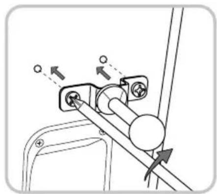
natural_image
Mechanical assembly diagram showing a lever mechanism with arrows indicating motion direction (no text or symbols)スピーカーの設置
EU DECLARATION OF CONFORMITY
We,
B&W Group Ltd.
whose registered office is situated at
Dale Road, Worthing, West Sussex, BN11 2BH, United Kingdom
declare under our sole responsibility that the products:
685 S2 and 686 S2
comply with the EU Electro-Magnetic Compatibility (EMC) Directive 89/336/EEC, in pursuance of which the following standards have been applied:
EN 61000-6-1 : 2007
EN 61000-6-3 : 2007
EN 55020 : 2007
EN 55013 : 2001
and comply with the EU General Product Safety 2001/95/EC, in pursuance of which the following standard has been applied:
EN 60065 : 2011
This declaration attests that the manufacturing process quality control and product documentation accord with the need to assure continued compliance.
The attention of the user is drawn to any special measures regarding the use of this equipment that may be detailed in the owner's manual.
Signed:

G Edwards
Executive Vice President, Operations
B&W Group Ltd.
Bowers & Wilkins
B&W Group Ltd
Dale Road
Worthing West Sussex
BN11 2BH England
T +44 (0) 1903 221 800
F +44 (0) 1903 221 801
info@bwgroup.com
www.bowers-wilkins.com
B&W Group (UK Sales)
T +44 (0) 1903 221 500
E uksales@bwgroup.com
B&W Group North America
T +1 978 664 2870
E marketing@bwgroupusa.com
B&W Group Asia Ltd
T+852 3 472 9300
E info@bwgroup.hk
Copyright © B&W Group Ltd. E&OE
Printed in China


- Welcome and thank you for choosing Bowers & Wilkins.
- Carton Contents
- Check in the carton for:
- Environmental Information
- Positioning
- Speaker Installation
- Speaker Positioning
- Conventional Stereo Systems
- Home Theatre Systems
- Stray Magnetic Fields
- Installazione
- Sistemi Home Theatre
- Luidspreker Installeren
- Luidsprekeropstelling
- Установка колонок
- 扬声器的安装
- スピーカーの設置
- B&W Group Ltd.
- Dale Road, Worthing, West Sussex, BN11 2BH, United Kingdom
- S2 and 686 S2
- Bowers & Wilkins
Brand : B&W
Model : 686 S2
Category : Loudspeaker