
CPE610 - Access Point TP-LINK - Free user manual and instructions
Find the device manual for free CPE610 TP-LINK in PDF.


| Product Type | Outdoor Access Point (CPE) |
| Brand | TP-Link |
| Model | CPE610 |
| Dimensions | Approximately 140 x 80 x 30 mm |
| Weight | Approximately 0.4 kg |
| Power Supply | Passive PoE 24 V or compatible PoE injector |
| Frequency | 5 GHz |
| Maximum Data Rate | Up to 300 Mbps |
| Antenna | Integrated directional antenna (high gain) |
| Ports | 1 Ethernet port 10/100 Mbps with PoE |
| Operating Mode | Access point, client, repeater (bridge mode) |
| Management | Web interface, Omada centralized software, hardware controller |
| Installation | Pole or wall mounting (mounting kit included) |
| Weatherproofing | Waterproof seal for weather protection |
| Maintenance and Cleaning | Clean with a soft dry cloth. Do not use chemicals. |
| Security | WPA/WPA2 encryption, MAC filtering, wireless isolation |
| Spare Parts and Repairability | Not user repairable. Spare parts not provided. |
| General Information | Outdoor use, compliant with CE, FCC standards. Warranty depends on retailer. |
Frequently Asked Questions - CPE610 TP-LINK
User questions about CPE610 TP-LINK
0 question about this device. Answer the ones you know or ask your own.
Ask a new question about this device
Download the instructions for your Access Point in PDF format for free! Find your manual CPE610 - TP-LINK and take your electronic device back in hand. On this page are published all the documents necessary for the use of your device. CPE610 by TP-LINK.
USER MANUAL CPE610 TP-LINK
Hardwareinstallation
natural_image
Pure mechanical diagram showing a lever mechanism with no text or symbolsNote: The image may differ from the actual product.
Typical Network Topology
■ Managed Mode
Via Centralized Management Software
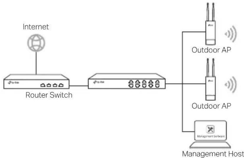
flowchart
graph LR
    A["Internet"] --> B["Router Switch"]
    B --> C["Network Switch"]
    C --> D["Outdoor AP"]
    C --> E["Outdoor AP"]
    C --> F["Management Host"]
A computer running the centralized management software, which can be in the same or different subnet with the APs, is used to centrally manage the APs.
You can get the corresponding software from our website http://www.tp-link.com
Via Hardware Controller (for Omada APs)

flowchart
graph LR
    A["Internet"] --> B["Router Switch"]
    B --> C["Outdoor AP"]
    B --> D["Outdoor AP"]
    B --> E["Hardware Controller"]
    B --> F["Host"]
The hardware controller can be in the same or different subnet with the APs. The management host is used to log in to the hardware controller to centrally manage the APs
■ Standalone Mode

flowchart
graph LR
    A["Internet"] --> B["Router"]
    B --> C["Switch"]
    C --> D["Outdoor AP"]
    D --> E["Host"]
Hardware Connection
Choose a method to connect your device according to the accessories.
■ Via PoE Switch
Some APs can be powered via the PSE device (such as a PoE switch) which complies with Power Source Class 2 (PS2) or Limited Power Source (LPS) of IEC 62368-1 Note: Availability depends on the actual product. Please refer to the product specifications.

■ Via PoE Adapter
Some APs can be powered via the PoE adapter Note: Availability depends on the actual product. Please refer to the product specifications.

Or

Hardware Installation
1 Choose a method to mount the device
■ Mounting the Device on a Pole
At the selected site, attach the device to a suitable point of the pole and then approximately align the device to the direction that you have oriented.

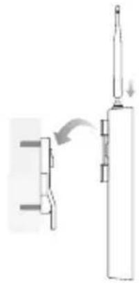
■ Mounting the Device on the Wall (for the product with mounting brackets)
Mount the mounting bracket to the preferred position in the wall Push and slide the device to lock it into place Then connect the antennas to the device
natural_image
Diagram showing a mechanical assembly with a cylindrical component and a vertical rod, no text or symbols present.2 Install the waterproof seal (For certain devices)
Before installing, fit the Ethernet cable through the spiral cover, bracket, and O-ring Then follow the steps as shown in the picture:
(1) Connect the Ethernet cable to the port
(2) Fit the O-Ring to the head of the bracket, and screw the bracket to the body of the device.
(3) Fit the Ethernet cable through the seal's slit with the thicker side towards the bracket
(4) Plug the seal to the bracket
(5) Screw the spiral cover to the bracket

Software Configurations
■ Managed Mode
To configure mass devices via a centralized management software or a wireless controller, please refer to the corresponding User Guide You can download the User Guide from our website http://www.tp-link.com
■ Standalone Mode
To configure a device through a web-based management system, please follow the steps below
- Launch a web browser and enter the IP address of your device in the address bar and press Enter
Note:
- For Omada APs, you can check the IP address through the product label.
-
For other products, the default IP address is 192.168.0.254 and the IP address of your computer should be set as 192.168.0.x ("x" is any number from 1 to 253).
-
Enter admin for both User Name and Password for login
- Change the default User Name and Password to protect your device, then start configuring the device.
natural_image
Technical diagram showing two mechanical assembly configurations with labeled components and directional arrows (no text or symbols present)natural_image
Diagram showing a mechanical assembly with a tool and a vertical component, no text or symbols presentnatural_image
Technical diagram showing two mechanical assembly configurations with labeled components and motion indicators (no text or symbols present)natural_image
Pure mechanical diagram showing a lever and shaft assembly without any text, numbers, or symbolsnatural_image
Pure mechanical diagram showing a lever and shaft assembly without any text, numbers, or symbolsnatural_image
Diagram of a mechanical device with a lever and handle, showing motion direction (no text or symbols)natural_image
Diagram showing a mechanical assembly with a lever and a cylindrical component, no text or symbols present.natural_image
Diagram showing a mechanical assembly with a lever and pin, no text or symbols presentnatural_image
Diagram showing a mechanical assembly with a piston and connecting rod (no text or symbols)natural_image
Diagram showing a mechanical assembly with a lever and a cylindrical component, no text or symbols presentnatural_image
Diagram showing a mechanical assembly with a tool and a vertical component, no text or symbols presentnatural_image
Diagram showing a mechanical assembly with a piston and lever mechanism (no text or symbols)- Keep the device away from fire or hot environments. DO NOT immerse in water or any other liquid.
- Do not attempt to disassemble, repair, or modify the device. If you need service, please contact us
- Do not use damaged charger or USB cable to charge the device
- Do not use any other chargers than those recommended.
- Do not use the device where wireless devices are not allowed
- Adapter shall be installed near the equipment and shall be easily accessible.
- Adapter should be used indoors where the ambient temperature is lower than or equal to 40 °C
- The plug on the power supply cord is used as the disconnect device, the socket-outlet shall be easily accessible.
Please read and follow the above safety information when operating the device. We cannot guarantee that no accidents or damage will occur due to improper use of device. Please use this product with care and operate at your own risk.
Español
TP-Link hereby declares that the device is in compliance with the essential requirements and other relevant provisions of directives 2014/53/EU, 2009/125/EC, 2011/65/EU, (EU) 2015/863
The original EU declaration of conformity may be found at https://www tp-link com/support/ce/
Español
https://www tp-link com/support/ce/
Ελληνικό
https://www tp-link com/support/ce/
Italiano
https://www tp-link com/support/ce/
Português
https://www tp-link com/support/ce/
Suomi
https://www tp-link com/support/ce/
Nederlands
https://www tp-link com/support/ce/
Svenska
https://www tp-link com/support/ce/
Norsk
https://www tp-link com/support/ce/
Dansk
For TP-Link Branded Products Only. For the information about warranty period, policy and procedures, please visit https://www.tp-link.com/en/support
THIS WARRANTY GIVES YOU SPECIFIC LEGAL RIGHTS, AND YOU MAY HAVE OTHER RIGHTS THAT VARY FROM STATE TO STATE (OR BY COUNTRY OR PROVINCE)
TO THE EXTENT ALLOWED BY LOCAL LAW, THIS WARRANTY AND THE REMEDIES SET FORTH ARE EXCLUSIVE AND IN LIEU OF ALL OTHER WARRANTIES, REMEDIES AND CONDITIONS
TP-Link warrants the TP-Link branded hardware product contained in the original packaging against defects in materials and workmanship when used normally in according with TP-Link's guidelines for some period which depends on the local service from the date of original retail purchase by the end-user purchaser.
Español
For technical support, the user guide and other information, please visit https://www tp-link com/support/, or simply scan the QR code.


- Hardwareinstallation
- Typical Network Topology
- ■ Managed Mode
- Via Centralized Management Software
- Via Hardware Controller (for Omada APs)
- ■ Standalone Mode
- Hardware Connection
- ■ Via PoE Switch
- ■ Via PoE Adapter
- Hardware Installation
- Choose a method to mount the device
- Install the waterproof seal (For certain devices)
- Software Configurations
- Note:
- Español
- Ελληνικό
- Italiano
- Português
- Suomi
- Nederlands
- Svenska
- Norsk
- Dansk
Brand : TP-LINK
Model : CPE610
Category : Access Point