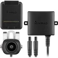
BC 20 - Rear Camera GARMIN - Free user manual and instructions
Find the device manual for free BC 20 GARMIN in PDF.


| Product type | Backup camera |
| Brand | Garmin |
| Model | BC 20 |
| Dimensions (approx.) | 60 x 40 x 30 mm |
| Weight (approx.) | 50 g |
| Power supply | 12-24 V DC via cable |
| Main functions | Wide-angle rear view, night vision, parking guide |
| Viewing angle | 120° (approx.) |
| Resolution | 640 x 480 pixels (approx.) |
| Waterproof rating | IPX7 (protection against temporary immersion) |
| Operating temperature | -20°C to 60°C |
| Compatibility | Garmin Drive series models, some touchscreen models |
| Mounting | Mounting bracket included (screw or adhesive attachment) |
| Connection | Coaxial cable with proprietary connector |
| Care and cleaning | Clean with a soft, dry cloth. Do not use abrasive products. |
| Safety | Electrical installation by a professional recommended. Do not expose to strong shocks. |
| Spare parts and repairability | Connection cable and bracket available. Repair by authorized center. |
| Warranty | 1 year (depending on country) |
Frequently Asked Questions - BC 20 GARMIN
User questions about BC 20 GARMIN
0 question about this device. Answer the ones you know or ask your own.
Ask a new question about this device
Download the instructions for your Rear Camera in PDF format for free! Find your manual BC 20 - GARMIN and take your electronic device back in hand. On this page are published all the documents necessary for the use of your device. BC 20 by GARMIN.
USER MANUAL BC 20 GARMIN
BC™ 20 Wireless Backup Camera Installation Instructions.... 2
BC™ 20 Wireless Backup Camera Installation Instructions....4
BC™ 20 Wireless Backup Camera Installation Instructions....7
BC™ 20 Wireless Backup Camera Installation Instructions.... 10
BC™ 20 Wireless Backup Camera Installation Instructions.... 13
BC™ 20 Wireless Backup Camera Installation Instructions.... 16
BC™ 20 Wireless Backup Camera Installation Instructions.... 19
BC™ 20 Wireless Backup Camera Installation Instructions.... 22
BC™ 20 Wireless Backup Camera Installation Instructions.... 25
BC™ 20 Wireless Backup Camera Installation Instructions.... 28
BC™ 20 Wireless Backup Camera Installation Instructions.... 31
BC™ 20 Wireless Backup Camera Installation Instructions.... 34
Garmin International, Inc.
1200 East 151st Street
Olathe, Kansas 66062, USA
Garmin (Europe) Ltd.
Liberty House, Houndown Business Park
Southampton, Hampshire, SO40 9LR UK
Garmin Corporation
No. 68, Zhangshu 2nd Road, Xizhi Dist.
New Taipei City, 221, Taiwan (R.O.C.)
Garmin ^® and the Garmin logo are trademarks of Garmin Ltd. or its subsidiaries, registered in the USA and other countries. BCTM is a trademark of Garmin Ltd. or its subsidiaries. These trademarks may not be used without the express permission of Garmin.
BC™ 20 Wireless Backup Camera Installation Instructions
WARNING
See the Important Safety and Product Information guide in the GPS device product box for product warnings and other important information.
Garmin ^® strongly recommends having an experienced installer with the proper knowledge of electrical systems install the device. Incorrectly wiring the power cable can result in damage to the vehicle or the battery and can cause bodily injury.
When connecting the power cable, do not remove the in-line fuse holder. To prevent the possibility of injury or product damage caused by fire or overheating, the appropriate fuse must be in place as indicated in the product specifications. In addition, connecting the power cable without the appropriate fuse in place will void the product warranty.
CAUTION
Always wear safety goggles, ear protection, and a dust mask when drilling, cutting, or sanding.
NOTICE
When drilling or cutting, always check what is on the opposite side of the surface.
These installation instructions do not apply to a specific vehicle type, and are meant as a guide when installing this product on your vehicle. For questions specific to your vehicle, you should contact the vehicle manufacturer.
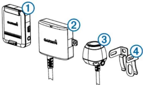
Item Description
| 1 | Wireless camera PND mountThe PND device must be powered through this mount to communicate with the camera. |
| 2 | Transmitter |
| 3 | Camera |
| 4 | Camera mounting bracket |
Tools Needed
- Drill and 0.36 in. (9.09 mm, or size T) drill bit
• #2 Phillips screwdriver - Screws, bolts, or cable ties (to secure the transmitter)
- Solderless wire-splice connector or solder and heat-shrink tubing
• RV sealant (optional)
Camera Mounting Considerations
When selecting a location to mount the camera, observe these considerations.
- You should test a mounting location before you permanently mount the camera.
- Installing the camera higher on the back of the vehicle provides a better viewing angle.
- The included bracket can be clipped onto a license plate or other similar surface, or it can be fastened to the back of the vehicle using the included self-tapping, panhead screws.
Transmitter Location and Wiring Considerations
When selecting a location to install the wireless transmitter, observe these considerations.
- You should test a proposed installation location before you permanently install the transmitter.
- Although the transmitter can reliably transmit the video signal over approximately 45 ft. (13.5 m), the location of the transmitter can affect this range.
- The closer you install the transmitter to the wireless camera PND mount, the more reliable the signal.
• The transmitter provides the best signal when either flat surface ① is pointing toward the wireless camera PND mount.
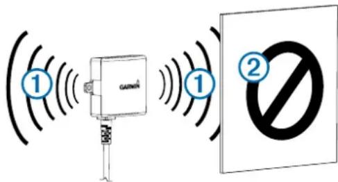
- Dense metal or appliances ② in the path of the transmitter greatly reduce the transmission distance.
- The fewer solid objects that exist between the path of the transmitter and the device, the more reliable the signal.
- If the distance between the camera and the transmitter exceeds the length of the included cable, additional extension cables can be used. A 50 ft. (15 m) extension cable can be purchased, and more than one extension cable can be installed. See your Garmin dealer or go to www.garmin.com for more information.
- The fuse holder located near the transmitter is not waterproof. Installing the fuse holder in a location that is exposed to the elements is not recommended.
- The connector between the camera and the transmitter is not waterproof. If you make this connection in a location exposed to the elements, you must make sure that the connection is waterproof.
Testing the Camera and Transmitter Location
1 Temporarily secure the camera in the preferred mounting location.
2 Temporarily place the transmitter in the preferred installation location, and connect it to power and to the camera.
TIP: If you do not want to splice into the wiring of your vehicle for this test, you can connect the transmitter and camera to a 12 Vdc battery.
3 Test the transmitter for correct operation by applying power to the PND device using the wireless camera PND mount. If you do not see video on the device at the preferred installation location, move the transmitter to another location and test it again.
4 Repeat steps 2–3 until the transmitter operates correctly.
5 Test the camera view by observing the video on the device.
6 If the camera does not provide the optimal view for your vehicle, move it to another location and test it again.
7 Repeat steps 5–6 until the camera mounting location provides the optimal view for your vehicle.
TIP: Make note of which direction is up when you are testing the camera view to ensure correct permanent installation.
Mounting the Camera
Before you permanently mount the camera, you should test the mounting location for the optimal view for your vehicle (Testing the Camera and Transmitter Location).
If you have already connected the camera to the bracket, you must first disassemble it.
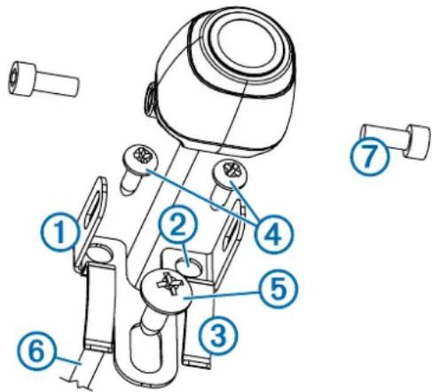
1 Place the bracket ① in the mounting location.
2 Select an option:
- If you are mounting the bracket directly on the surface of your vehicle, mark the locations of the two holes on the bracket ②.
- If you are installing the bracket on a license plate, remove one of the license plate screws and clip the bracket in place so the hole on the bracket ③ lines up with the hole on the license plate.
3 Secure the bracket to the vehicle using either the included self-tapping screws ④ or the license-plate screw you removed in step 2 ⑤.
4 Place the camera in the bracket, and determine the best place for the camera cable ⑥ to enter the vehicle.
5 Using an appropriate drill bit, drill a hole for the camera cable to enter the vehicle.
6 Feed the camera cable through the hole and route it to the transmitter location.
15 m (50 ft.) extension cables can be purchased separately, if needed.
7 Secure the camera in the bracket using the included hex bolts ⑦.
8 Adjust the angle of the camera and tighten the hex bolts using the included hex key.
9 Apply RV sealant around the cable where it enters the vehicle (optional).
Installing the Transmitter
Before you permanently install the transmitter, you must test the installation location for correct operation (Testing the Camera and Transmitter Location).
1 Secure the transmitter to the installation location using hardware appropriate for the location, such as screws, bolts, or cable ties.
The fuse holder located near the transmitter is not waterproof. Installing the fuse holder in a location that is exposed to the elements is not recommended.
2 Connect the camera and transmitter cables.
The connector between the camera and the transmitter is not waterproof. If you make this connection in a location exposed to the elements, you must make sure that the connection is waterproof.
3 Connect the power cable ① from the transmitter to a 12–24 VDC power source, preferably a reverse lamp ②, using a solderless wire-splice connector (not included).
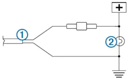
NOTE: Connecting the transmitter to an always-on 12-24 VDC source (such as a running lamp) instead of a reverse lamp requires you to manually switch power to the transmitter. The transmitter may drain your vehicle battery if it is left on.
4 If you did not use a solderless wire-splice connector, solder and heat-shrink the electrical connections to protect them from the elements.
Using the Camera
The camera shows video on the device in different ways, depending on how you connected the power to the transmitter.
1 Select an option to show video:
- If you connected the transmitter to a reverse lamp (recommended), place the vehicle into reverse. The device automatically shows video from the backup camera.
- If you connected the transmitter to a running lamp or other steady 12 VDC source, select the camera icon on the device to show video from the backup camera.
2 Select an option to resume normal device operation:
- If you connected the transmitter to a reverse lamp (recommended), take the vehicle out of reverse. The device automatically resumes normal operation.
- If you connected the transmitter to a running lamp or other steady 12 VDC source, select the camera icon on the device to resume normal operation.
Aligning the Guidance Lines
Guidance lines provide a visual representation of the vehicle's path when in reverse. For best reference, they should be aligned to reflect the outside edges of the vehicle.
1 Position the vehicle with one side closely aligned to a curb, driveway, or parking stall lines.
You may want to position the vehicle in the center of a parking stall, and then pull forward into the next stall. This allows you to use the parking stall lines in the rear of the vehicle as reference points for alignment.
The curb, driveway, or parking stall lines should be clearly visible on the device.
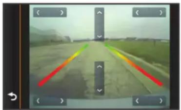
2 From the camera view, select ≧ Adjust.
3 Use the arrows in the corners of the screen to move the guidance lines to match the angle and position of the curb, driveway, or parking stall lines.
The guidance lines should appear directly on top of your reference points.
natural_image
Street view from a vehicle showing a road with colored lane markings (no readable text or symbols)4 Use the arrows in the center of the screen to move the guidance lines up or down.
The red section of the guidance lines should be aligned with the rear of your vehicle.
5 If necessary, reposition the vehicle with the other side closely aligned to a curb, driveway, or parking stall lines, and repeat the alignment process.
You should attempt to keep the guidance lines symmetrical, even if your vehicle is not in perfect alignment with the curb, driveway, or parking stall lines.
6 Select when alignment is complete.
Showing or Hiding Guidance Lines
1 Select
2 Select an option:
- To show the guidance lines on the screen, select Show Lines.
- To hide the guidance lines on the screen, select Hide Lines.
Restoring Alignment
You can reset the guidance lines to their default settings.
1 Select ≈ Restore.
2 Select Yes.
Pairing the Transmitter and Device Mount
The transmitter and wireless camera PND mount come paired from the factory. If the transmitter and the PND mount are properly installed and you are not receiving video, you can try to re-pair the transmitter and the PND mount.
1 Verify there is no power to the transmitter by placing the vehicle in park or turning off the applicable steady power source.
2 Turn on the PND device connected to the wireless camera PND mount.
3 On the wireless camera PND mount, hold PAIR until Start Pairing appears on the PND device.
If Start Pairing does not appear on the PND device, make sure the wireless camera PND mount is correctly connected to power.
4 Apply power to the transmitter by placing the vehicle in reverse or turning on the applicable steady power source.
After approximately five seconds, Pairing OK appears on the PND device.
5 Power cycle both the wireless camera PND mount and the transmitter by turning them both off and then back on again.
6 If the transmitter and wireless camera PND device mount do not pair successfully, repeat steps 1–4.
Specifications
| Specification Value | |
| Camera sensor 1/3.7-type CMOS | |
| Camera resolution 640 × 480 | |
| Camera angle (vertical) 115° | |
| Camera angle (horizontal) 140° | |
| Camera and transmitter input voltage 9–28 | VDC |
| Fuse 500 mA, fast-blow | |
| Camera and transmitter current usage 150 | mA @ 12 VDC |
| Camera and transmitter waterproof rating I | EC 60529 IPX7 |
| Camera temperature range -40° to 185°F (-40° to 85°C) | |
| Transmitter and PND mount temperature range | -4° to 158°F (-20° to 70°C) |
| Wireless transmission type 2.4 GHz ISM radio band | |
| Wireless transmission distance 45 ft. (13.5 m) | |
BC™ 20 Wireless Backup Camera Installation Instructions
AVERTISSEMENT
natural_image
Street view from a vehicle camera showing a painted road with colored directional arrows (no text or symbols)BC™ 20 Wireless Backup Camera Installation Instructions
ATTENZIONE
natural_image
Grayscale photo of a road with colored directional arrows indicating traffic flow (no text or symbols)BC™ 20 Wireless Backup Camera Installation Instructions
WARNING
natural_image
Street view from a vehicle showing a painted road with red and green lane markings (no text or symbols visible)BC™ 20 Wireless Backup Camera Installation Instructions
AVISO
natural_image
Grayscale photo of a road with colored directional arrows indicating traffic flow (no text or symbols)BC™ 20 Wireless Backup Camera Installation Instructions
AVISO
natural_image
Road scene with colored lane markings and directional arrows, no visible text or symbolsBC™ 20 Wireless Backup Camera Installation Instructions
WAARSCHUWING
natural_image
Grayscale photo of a road with visible lane markings and directional arrows, no readable text or symbolsBC™ 20 Wireless Backup Camera Installation Instructions
ADVARSEL
2 Vælg en funktion:
natural_image
Aerial view of a highway with colored directional arrows indicating traffic flow (no text or symbols visible)BC™ 20 Wireless Backup Camera Installation Instructions
VAROITUS
Kohde Kuvaus
natural_image
Road view from a vehicle camera interface showing lane markings and directional arrows (no readable text or symbols)BC™ 20 Wireless Backup Camera Installation Instructions
ADVARSEL
natural_image
Road view with colored lane markings and directional arrows, no readable text or symbolsBC™ 20 Wireless Backup Camera Installation Instructions
WARNING
natural_image
Street view with visible road and directional arrows (no readable text or symbols)BC™ 20 Wireless Backup Camera Installation Instructions
OSTRZEŻENIE
2 Wybierz opcję:
natural_image
Grayscale photo of a road with colored directional arrows indicating navigation or movement (no text or symbols visible)
- BC™ 20 Wireless Backup Camera Installation Instructions
- WARNING
- CAUTION
- NOTICE
- Tools Needed
- Camera Mounting Considerations
- Transmitter Location and Wiring Considerations
- Testing the Camera and Transmitter Location
- Mounting the Camera
- Installing the Transmitter
- Using the Camera
- Aligning the Guidance Lines
- Showing or Hiding Guidance Lines
- Restoring Alignment
- Pairing the Transmitter and Device Mount
- AVERTISSEMENT
- ATTENZIONE
- AVISO
- WAARSCHUWING
- ADVARSEL
- VAROITUS
- OSTRZEŻENIE
Brand : GARMIN
Model : BC 20
Category : Rear Camera