
PTK 2000 A1 - Service après-vente PARKSIDE - Free user manual and instructions
Find the device manual for free PTK 2000 A1 PARKSIDE in PDF.


| Product type | Circular table saw |
| Brand | Parkside |
| Model | PTK 2000 A1 |
| Table dimensions | 580 x 545 mm (without extensions); 580 x 1010 mm (with extensions) |
| Weight | Approx. 22 kg |
| Power supply | 230-240 V~, 50 Hz |
| Power consumption | 1,800 W (S1) / 2,000 W (S6 40%) |
| No-load speed | 3,200 min⁻¹ or 5,000 min⁻¹ (2-speed switch) |
| Maximum cutting depth | 85 mm (at 90°); 63 mm (at 45°) |
| Cutting angle | 0° to 45° (left tilt) |
| Saw blade (diameter / bore) | 254 mm / 30 mm |
| Number of teeth supplied | 24 teeth (pre-installed) + 48 teeth (additional) |
| Laser guide | Class 2 laser, 650 nm, < 1 mW, powered by 2 AAA batteries |
| Dust extraction port | Diameter 34 mm |
| Main functions | Rip cuts, cross cuts (with fence), miter cuts, laser guide, height and angle adjustment |
| Safety | Blade guard, riving knife, emergency stop, overload protection, residual current device recommended |
| Maintenance | Regular cleaning, oiling of rotating parts, replace blade if dull |
| Spare parts | Available at www.grizzlytools.shop (e.g., blade guard, blades, fence, laser) |
| Warranty | 3 years (France and Belgium) – private use only |
| Intended use | Longitudinal and cross cutting of wood (no round wood, no metal) |
| Sound level (LpA) | 97 dB(A) with uncertainty KpA = 3 dB |
| Protection class | II (double insulation) |
Frequently Asked Questions - PTK 2000 A1 PARKSIDE
User questions about PTK 2000 A1 PARKSIDE
0 question about this device. Answer the ones you know or ask your own.
Ask a new question about this device
Download the instructions for your Service après-vente in PDF format for free! Find your manual PTK 2000 A1 - PARKSIDE and take your electronic device back in hand. On this page are published all the documents necessary for the use of your device. PTK 2000 A1 by PARKSIDE.
USER MANUAL PTK 2000 A1 PARKSIDE
natural_image
Black industrial machine with a flat workbench and metal frame, no visible text or symbols

Tischkreissäge / Table Saw / Scie circulaire de table PTKS 2000 H5
DE AT CH
Tischkreissäge
Translation of the original instructions
NL BE
Tafel cirkelzaag
Before reading, unfold the page containing the illustrations and familiarise yourself with all functions of the device.
FR BE
GB / MT Translation of the original instructions Page
Service-Center....19
Importeur 19
(k) Ringschlüssel SW 10/22
(i) Gabelschlüssel SW 8/10

Intended purpose....20
General description......21
Extent of the delivery 21
Overview....21
Functional description....21
Technical data....21
Safety instructions....22
Symbols and icons 22
General safety instructions for power tools 22
Safety information for circular table saws 23
Safety Instructions for Handling the Laser 25
Safety Instructions for Handling Batteries 25
Residual Risks 25
Electrical Connection 26
Important Instructions....26
Faulty Electrical Connection Cable 26
Alternating Current Motor 26
Assembly....26
Assembly, Replacement of Parts and Adjustments....26
Assembling the frame and tablewidth extender....26
Mount/adjust the riving knife....27
Attaching/removing the laser; inserting the battery.....27
Mounting / dismounting the saw blade guard 27
Connect the suction device....27
Replacing the Table Insert....27
Attaching/changing the saw blade 27
Before putting into operation 28
Operation 28
Switching on and off 28
Changing the speed....28
Adjusting the Cutting Depth 28
Working with the Parallel Stop 28
Adjusting the cutting width 28
Attaching/removing the stop rail on the parallel guide/cross stop....28
Adjusting the scale of the parallel stop....29
Transverse stop 29
Angle Adjustment....29
Using the Laser 29
Adjusting the Laser 29
Use 29
Working Instructions....29
Performing Longitudinal Cuts 29
Cutting narrow Workpieces....29
Cutting very narrow Workpieces....30
Performing Bevel Cuts 30
Performing Transverse Cuts 30
Cutting Chipboard 30
Transport....30
Overload protection 30
Cleaning and Servicing.... 30
Cleaning....30
General maintenance work 31
Storage....31
Waste disposal and environmental protection ..... 31
Spare parts/Accessories 31
Trouble shooting 31
Guarantee 32
Repair Service....32
Service-Center 32
Importer 32
Translation of the original EC declaration of conformity....171
Introduction
Congratulations on the purchase of your new device. With it, you have chosen a high quality product.
During production, this equipment has been checked for quality and subjected to a fi nal inspection. The functionality of your equipment is therefore guaranteed.

The operating instructions constitute part of this product.
They contain important information on safety, use and disposal. Before using the product, familiarise yourself with all of the operating and safety instructions. Use the product only as described and for the applications specified. Keep this manual safely and in the event that the product is passed on, hand over all documents to the third party.
Intended purpose
The table circular saw is used for cutting all types of wood lengthwise and crosswise (only with the transverse stop), depending on the machine size. All types of round timbers must not be cut with it. The machine may be used only for its prescribed purpose.
Any other use beyond that is considered to be not in accordance with the designated purpose. The user/operator is liable for all types of resulting damage or injury and not the manufacturer. The only saw blades which may be used are those which are suitable for the machine (HM or CV saw blades).
The use of any type of HSS saw blades and cutting discs is prohibited. Use in accordance with the designated purpose is also deemed to include observance of the safety instructions, as well as the assembly and operating instructions in the operating manual. Individuals who operate and maintain the machine must be familiar with it and must have been instructed in possible hazards. Moreover, the latest accident prevention regulations must be strictly observed. Other general rules in the fi elds of occupational health and safety technology must be complied with.
Caution! When using equipment, certain safety precautions must be complied with in order to avoid injuries and damage. You should therefore read these operating instructions / safety instructions carefully. Keep these in a safe place so that the information is available to you at all times. Should you give the device to anyone else, please give them these operating instructions / safety instructions as well. We assume no liability for accidents or damage caused by failure to observe these instructions or the safety instructions. Changes to the machine will cause the manufacturer's liability with respect to any resulting damage to be completely excluded. Even when the device is used in accordance with the designated purpose, it is nevertheless not possible to completely eliminate certain residual risk factors. Due to the design and structure of the machine, the following risks may occur:
- Touching the saw blade in the area of the saw which is not covered;
- Reaching into the running saw blade (cuts)
- Kickback of workpieces and workpiece parts.
- Saw blade breaks.
- Ejection of faulty hard metal parts of the saw blade.
• Hearing damage if the necessary hearing protection is not used. - Emissions of wood dust which are harmful to the health when used in closed rooms.
Please note that the use of our devices in accordance with the designated purpose does not include commercial, handicraft or industrial applications. We assume no warranty if the device is used in commercial, handicraft or industrial businesses or for equivalent purposes.
General description
The illustrations are on the fold-out pages.
Extent of the delivery
Carefully unpack the appliance and check that it is complete:
1x Saw table with pre-assembled carbide-tipped saw blade with 24 teeth
1x carbide-tipped saw blade with 48 teeth (additionally enclosed)
1x Blade guard with mounting material + 2x nuts
1x Laser + 2x screws
2x Batteries 1.5V AAA
1x Guide rail
1x Parallel stop
1x Transverse stop + Stop rail
2x Table width extender
1x Push stick
4x Legs
2x Central struts, short
2x Central struts, long
4x Rubber feet
2x Stand brackets
4x Table supports, short
1x Instruction for use
Mounting Material
(a) Hexagonal bolt with collar, 16 pieces;
(b) Carriage bolt, 28 pieces;
(c) Washer, 8 pieces;
(d) Spring washer, 8 pieces;
(e) Nuts, 16 pieces;
(f) Self-securing nuts, 20 pieces;
Tools
- (h) Hexagon socket wrench HX 6
- (k) Ring spanner AF 10/22
- (i) Open-ended spanner AF 8/10

Additional tools required
- Phillips screwdriver
Overview
1 Saw table aw blade guard
3 Riving knife (not visible)
4 Saw blade (not visible)
5 Table insert
6 Table width extender
7 Guide rail
8 Scale
9 Handwheel
10 Base frame
11 Clamping screw
12 Crank handle
13 On/off switch
14 Speed switch
15 Cam lever
16 Parallel stop
2 17 Suction adapter push stick
4 19 Legs (4x) Central struts, short (2x)
21 Central struts, long (2x)
22 Rubber feet (4x)
23 Stand brackets (2x)
5 24 Table brackets, short
9 25 Attachment points
14 26 Countersunk screws of the table insert
15 27 Fixing screws of the riving knife
17 28 Laser laser switch 30 Laser aperture
31 Battery cover
19 32 Screw with knurled nut and locknut
25 33 Groove tnurled screw
35 Stop rail 36 Transverse stop
35 37 Overload protection switch
Functional description
The table circular saw is used for cutting all types of wood lengthwise and crosswise (only with the transverse stop), depending on the machine size. All types of round timbers must not be cut with it.
Technical data
Bench circular saw....PTKS 2000 H5
AC motor....230-240 V\~ 50 Hz
Idle speed n_1 5000 min ^-1
Power consumption 1800 W (S1)**
Power consumption 2000 W (S6 40%)*
Idle speed n_2 3200 min ^-1
Power consumption 500 W (S1)**
Operating mode ....S6 40%*, S1**
Safety class .... □ II
Protection category.... IPXO
Saw blade
Hard metal blade (dimensions to be used)
HW 24....∅ 254 × ∅ 30 × 2.8 mm
HW 48......or ∅ 254 × ∅ 30 × 2.6 mm
Thickness of saw blade's main blade 1,8 mm
Idling speed saw blade, n max. 7000 min ^-1
Number of teeth....24 / 48
Saw blade, swivelling....90 - 45°
Thickness riving knife....2.5 mm
min. Workpiece size WxLxH 10x50x1 mm
Table size....580 x 545 mm
Table size with all extensions 580 x 1010 mm
Cutting height max. 90°....85 mm
Cutting height max. 45°....63 mm
Height adjustment 0 - 85 mm
Extraction connection....ø 34 mm
Weight 22 kg
Laser
Laser class....2
Laser wavelength 650 nm
GB MT
Laser power .... < 1 mW Laser module power supply .... 2 x 1.5 V Micro (AAA) Sound pressure level ( L_RA ) .... 97 dB(A); K_pA = 3 dB Sound power level ( L_WA ) measured .... 110 dB(A); K_WA = 3 dB
* Operating mode S6 40%: Continuous operation with intermittent load (cycle time 10 min). In order not to heat the motor more than permitted, the motor may only be operated for 40% of the cycle time with the stated nominal power and must then continue running for 60% of the cycle time without a load.
**Operating mode S1: Continuous operation with constant load
This appliance is intended to be operated using a mains supply network with a system impedance (internal resistance of the mains) Zmax on the transfer point (house connection) of maximum 0.369 Ohm. The user must ensure that the appliance is only operated using a mains supply network meeting the requirements. If necessary, local power supply companies can be consulted with regards to the system impedance.
- The specified total vibration value and the stated noise emission value have been measured according to a standardised test method and can be used to compare one power tool with another.
- The specified total vibration value and the stated specified noise emission value can also be used for a provisional assessment of the load.

Warning:
The vibration and noise emissions may deviate from the specified values during actual use of the power tool, depending on how the power tool is being used and, in particular, what kind of material is being worked on. Safety measures for the protection of the operator are to be determined that are based on an estimate of the actual vibration load under the real operating conditions (for this, all parts of the operating cycle are to be taken into account, for example, times in which the electric tool is turned off, and those during which it is turned on but running without a load).
Safety instructions
CAUTION! The following basic safety precautions must be observed while using electric tools to protect against electric shock, injury and risk of fi re. Please read all instructions before using this electric tool and keep the safety instructions in a safe place.
Symbols and icons
Symbols on the appliance:

Carefully read these Operating Instructions.

Wear eye protection.

Wear ear protection.

Wear breathing protection.

Caution - Risk of injury.
Never reach into the running blade.

Do not expose the unit to rain. The device must not be wet, nor should it be operated in a moist environment.

Caution! - Laser radiation. Do not look into the beam. Laser class 2
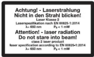
This label is attached to the saw blade guard.

Safety class II (Double Isolated)

Electrical appliances must not be disposed of with the domestic waste.

Speed 3200 min -1

Speed 5000 min ^-1

Max. diameter, saw blade: ø 254 mm
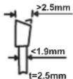
The saw blade should be wider than 2.5 mm at the saw teeth
The saw blade should be no thicker than 1.9 mm. The riving knife is 2.5 mm thick
Graphical symbol additionally on the saw blades

Caution - a damaged blade must not be used under any circumstances. Replace the saw blade immediately.

Specifi ed rotation direction of the saw blade
Symbols in the manual

Warning symbols with information on damage and injury prevention.

Instruction symbols with information on preventing damage.

Help symbols with information on improving tool handling.

Hazard symbol with information on the prevention of personal injury caused by electric shock.

Warning! Electric shock hazard. Always unplug the device before working on it.
General safety instructions for power tools

WARNING! Read all safety directions and instructions. Omissions in the compliance with safety directions and instructions can cause electrical shock, fire and/or severe injuries.
Retain all safety directions and instructions for future use.
The term "Power Tools" used in the safety instructions refers to mains-operated power tools (with power cord) and to battery-operated power tools (without power cord).
1) WORK AREA SAFETY
a) Keep work area clean and well lit. Cluttered or dark areas invite accidents.
b) Do not operate power tools in explosive atmospheres, such as in the presence of fl ammable liquids, gases or dust. Power tools create sparks which may ignite the dust or fumes.
c) Keep children and bystanders away while operating a power tool. Distractions can cause you to lose control.
2) ELECTRICAL SAFETY
a) Power tool plugs must match the outlet. Never modify the plug in any way. Do not use any adapter plugs with earthed (grounded) power tools. Unmodified plugs and matching outlets will reduce risk of electric shock.
b) Avoid body contact with earthed or grounded surfaces, such as pipes, radiators, ranges and refrigerators. There is an increased risk of electric shock if your body is earthed or grounded.
c) Do not expose power tools to rain or wet conditions. Water entering a power tool will increase the risk of electric shock.
d) Do not abuse the cord. Never use the cord for carrying, pulling or unplugging the power tool. Keep cord away from heat, oil, sharp edges or moving parts. Damaged or entangled cords increase the risk of electric shock.
e) When operating a power tool outdoors, use an extension cord suitable for outdoor use. Use of a cord suitable for outdoor use reduces the risk of electric shock.
f) If operating a power tool in a damp location is unavoidable, use a residual current device protected supply. Use of an RCD reduces the risk of electric shock.
3) PERSONAL SAFETY
a) Stay alert, watch what you are doing and use common sense when operating a power tool. Do not use a power tool while you are tired or under the influence of drugs, alcohol or medication. A moment of inattention white operating power tools may result in serious personal injury.
b) Use personal protective equipment. Always wear eye protection. Protective equipment such as dust mask, non-skid safety shoes, hard hat, or hearing protection used for appropriate conditions will reduce personal injuries.
c) Prevent unintentional starting. Ensure the switch is in the off-position before connecting to power source and/or battery pack, picking up or carrying the tool. Carrying power tools with your fi nger on the switch or energising power tools that have the switch on invites accidents.
d) Remove any adjusting key or wrench before turning the power tool on. A wrench or a key left attached to a rotating part of the power tool may result in personal injury.
e) Do not overreach. Keep proper footing and balance at all times. This applies especially when working on slopes. This enables better control of the power tool in unexpected situations.
f) Dress properly. Do not wear loose clothing or jewellery. Keep your hair, clothing and gloves away
from moving parts. Loose clothes, jewellery or long hair can be caught in moving parts.
g) If devices are provided for the connection of dust extraction and collection facilities, ensure these are connected and properly used. Use of dust collection can reduce dust-related hazards.
h) Walk when holding the device in your hand. Do not run.
i) Do not touch any of the dangerous moving parts before you have removed the battery and all moving parts have come to a complete standstill. There is a risk of injury.
a) Do not force the power tool. Use the correct power tool for your application. The correct power tool will do the job better and safer at the rate for which it was designed.
b) Do not use the power tool if the switch does not turn it on and off. Any power tool that cannot be controlled with the switch is dangerous and must be repaired.
c) Disconnect the plug from the power source and/or the battery pack from the power tool before making any adjust -ments, changing accessories, or storing power tools. Such preventive safety measures reduce the risk of starting the power tool accidentally.
d) Store idle power tools out of the reach of children and do not allow persons unfamiliar with the power tool or these instructions to operate the power tool. Power tools are dangerous in the hands of untrained users.
e) Maintain power tools. Check for misalignment or binding of moving parts, breakage of parts and any other condition that may affect the power tool's operation. If damaged, have the power tool repaired before use. Many accidents are caused by poorly maintained power tools.
f) Keep cutting tools sharp and clean. Properly maintained cutting tools with sharp cutting edges are less likely to bind and are easier to control.
g) Use the power tool, accessories and tool bits etc. in accordance with these instructions, taking into account the working conditions and the work to be performed. Use of the power tool for operations different from those intended could result in a hazardous situation.
4) POWER TOOL USE AND CARE
5) SERVICE
a) Have your power tool serviced by a qualified repair person using only identical replacement parts. This will ensure that the safety of the power tool is maintained.
Safety information for circular table saws
1) Safety instructions for protective cover
a) Have protective covers installed. Protective covers must be in good working order and correctly installed. Protective covers that are loose, damaged or not working correctly must be repaired or replaced.
b) Before switching on the power tool, make sure that the saw blade is not touching the protective cover, the riving knife or the workpiece. Accidental contact of these components with the saw blade can lead to danger.
c) Adjust the riving knife as described in this instruc-
tion manual. Incorrect spacing, position and alignment can be the reason why the riving knife does not effectively prevent kickback.
d) For the riving knife to work, it must be able to engage with the workpiece. If the workpiece is too short, the riving knife will not be able to engage and will be ineffective. Under these conditions, the riving knife cannot prevent kickback.
e) Use the appropriate saw blade for the riving knife. For the riving knife to work properly, the saw blade diameter must match the corresponding riving knife, the saw blade's main blade must be thinner than the riving knife and the tooth width must be greater than the thickness of the riving knife.
2) Safety instructions for sawing procedures
a)
DANGER! Do not put your fingers or hands near the saw blade or in the sawing area. A moment of inattention or slipping could direct your hand towards the saw blade and cause serious injury.
b) Only feed the workpiece into the saw blade against the direction of rotation. Feeding the workpiece in the same direction as the saw blade's direction of rotation above the table can result in the workpiece and your hand being pulled into the saw blade.
c) When making longitudinal cuts, never use the mitre fence to feed the workpiece. When making cross cuts with the mitre fence, never use the rip fence in addition to the mitre fence to adjust the length. Simultaneously guiding the workpiece with the rip fence and the mitre fence increases the likelihood of the saw blade jamming and kickback.
d) For longitudinal cuts, always apply the feed force to the workpiece between the stop rail and the saw blade. Use a push stick if the distance between the stop rail and the saw blade is less than 150 mm, and a sliding block if the distance is less than 50 mm. Work aids such as these ensure that your hand remains at a safe distance from the saw blade.
e) Only use the push stick supplied by the manufacturer or one that has been made according to instructions. The push stick ensures there is sufficient distance between the hands and the saw blade.
f) Never use a damaged or sawn push stick. A damaged push stick can break and cause your hand to get caught in the saw blade.
g) Do not operate the tool "freehand". Always use the rip fence or the mitre fence to set up and guide the workpiece. "Freehand" means supporting or guiding the workpiece with the hands instead of using a rip fence or mitre fence. Free-hand sawing leads to misalignment, jamming and kickback.
h) Never reach around or over a rotating saw blade. Reaching for a workpiece can lead to unintentional contact with the rotating saw blade.
i) Support long and/or wide workpieces behind and/or to the side of the saw table so that they remain horizontal. Long and/or wide workpieces tend to tip off the edge of the saw table; this leads to loss of control, jamming of the saw blade and kickback.
i) Feed the workpiece evenly. Do not bend or twist the workpiece. If the saw blade jams, switch off the power tool immediately, disconnect the mains plug and rectify the cause of the jamming. Jamming of the saw blade by the workpiece can lead to kickback or blocking of the motor.
k) Do not remove sawn-off material while the saw is running. Sawn-off material can get stuck between the saw blade and the stop rail or in the protective cover. Your fingers can be pulled into the saw blade if you attempt to remove the sawn-off material. Switch the saw off and wait for the saw blade to come to a standstill before removing the material.
1) For longitudinal cuts on workpieces thinner than 2 mm, use an additional rip fence that is in contact with the table surface. Thin workpieces can get wedged under the rip fence and cause kickback.
3) Spring-back - causes and corresponding safety instructions
Kickback is the sudden reaction of the workpiece when the saw blade becomes hooked or jammed or the workpiece is cut at an angle to the saw blade. Kickback also occurs when part of the workpiece is caught between the saw blade and rip fence or another stationary object.
In most cases, when a kickback occurs, the workpiece is caught by the rear part of the saw blade, lifted off the saw table and thrown towards the operator.
Kickback is caused by wrongly or incorrectly operating the circular table saw. It can be avoided by suitable precautionary measures, such as those described below.
a) Never stand in direct line with the saw blade. Always keep to the side of the saw blade on which the stop rail is also located. In the event of a kickback, the workpiece can be thrown at high speed at people standing in front of and in line with the saw blade.
b) Never reach over or behind the saw blade to pull or support the workpiece. Accidental contact with the saw blade may occur or kickback may cause your fingers to be pulled into the saw blade.
c) Never hold or press the workpiece against the rotating saw blade. Pressing the workpiece against the saw blade causes jamming and kickback.
d) Align the stop rail parallel to the saw blade. An un-aligned stop rail presses the workpiece against the saw blade and causes kickback.
e) Support large plates to reduce the risk of kickback due to a jammed saw blade. Large plates can bend under their own weight. Plates must be supported wherever they overhang the table surface.
f) When sawing workpieces that are twisted, knotted, warped or do not have a straight edge, take special care to guide them with a mitre fence or along a stop rail. A warped, knotted or twisted workpiece is unstable and will cause the kerf to misalign with the saw blade, causing jamming and kickback.
g) Never saw several workpieces stacked on top of each other or one behind the other. The saw blade could catch one or more parts and cause a kickback.
h) If you want to restart a saw whose saw blade is stuck in the workpiece, centre the saw blade in the sawing gap so that the teeth are not jammed in the workpiece. If the saw blade jams, it can lift the workpiece and cause a kickback when the saw is restarted.
i) Keep saw blades clean, sharp and suffi ciently set. Never use warped saw blades or saw blades with cracked or broken teeth. Sharp and properly set saw blades minimise jamming, blocking and kickback.
4) Safety information for operating circular table saws
a) Switch off the circular table saw and disconnect it from the mains before removing the table insert, changing the saw blade, making adjustments to the riving knife or the saw blade's protective cover and when the machine is left unattended. Taking precautionary measures prevents accidents.
b) Never leave the circular table saw running unattended. Switch the power tool off and never leave it before it has come to a complete standstill. A running saw that is left unattended is an uncontrolled hazard.
c) Set up the circular table saw in a place that is level, well lit and where you can stand and balance safely. The installation site must offer enough space to handle the size of your workpieces. Untidy, unlit work areas and uneven, slippery floors can lead to accidents.
d) Regularly remove shavings and sawdust from under the saw table and/or from the dust extraction system. Accumulated sawdust is fl ammable and can self-ignite.
e) Secure the circular table saw. A circular table saw that is not properly secured can move or tip over.
f) Remove adjustment tools, wood residues, etc. from the circular table saw before switching it on. Distraction or possible entrapment can be dangerous.
g) Always use the right size saw blades with the appropriate locating holes (e.g. diamond or round). Saw blades that do not fit in the saw's assembly parts run unevenly and lead to a loss of control.
h) Never use damaged or incorrect saw blade assembly materials such as fl anges, washers, screws or nuts. The saw blade assembly materials were designed specifically for your saw to ensure optimal performance and dependability.
i) Never stand on the circular table saw and do not use the circular table saw as a step stool. Serious injury can occur if the power tool tips over or if you accidentally come into contact with the saw blade.
i) Make sure that the saw blade is mounted in the correct direction of rotation. Do not use grinding discs or wire brushes with the circular table saw. Improper installation of the saw blade or the use of non-recommended accessories can lead to serious injuries.
Safety Instructions for Handling the Laser
- Caution: Laser radiation - Do not look into the beam - Laser class 2
- The label is attached to the saw blade guard (2) near the laser (28).
Safety Instructions for Handling Batteries
1 Ensure at all times that the batteries are inserted with the correct polarity (+ and -), as shown on the battery itself.
2 Do not short-circuit the batteries.
3 Do not charge non-rechargeable batteries.
4 Do not overcharge the battery!
5 Do not mix old and new batteries or batteries of a different type or from different manufacturers! Replace all batteries of a set at the same time.
6 Remove used batteries immediately out of the device and dispose of them correctly!
7 Do not heat the batteries!
8 Do not carry out any welding or soldering work directly to the batteries!
9 Do not take the batteries apart!
10 Do not deform the batteries!
11 Do not throw the batteries into the fire!
12 Store the batteries out of the reach of children.
13 Do not allow children to replace the batteries without supervision!
14 Do not store the batteries close to a fire, cookers or other sources of heat. Do not place the battery in direct sunlight and do not use or store it in motor vehicles in hot weather.
15 Store used batteries in the original packaging and keep them away from metal objects. Do not mix (up) unpacked batteries! Otherwise this may cause the battery to short-circuit, resulting in damage, burns or even the danger of fire.
16 Remove batteries from the device if this is not going to be used for a prolonged period, unless it is to be used in emergencies!
17 NEVER touch batteries which have leaked without appropriate protection. If the leaked liquid comes into contact with the skin, you should rinse off this area of the skin immediately under running water. Make sure at all events that your eyes and mouth do not come into contact with the liquid. If they do, seek medical advice immediately.
18 Clean the battery contacts and the equivalent contacts in the device before inserting the batteries.
Residual Risks
This power tool has been constructed in accordance with the latest technology and the generally recognised safety regulations. Nevertheless, it is possible that individual residual risks may occur during operation.
- Electrical hazard if improper electrical connection cables are used.
- In addition, concealed residual risks may be present in spite of all the precautions that have been taken.
- Residual risks can be minimised by observing the „Safety instructions“ and „Use in accordance with the designated purpose“, as well as the operating instructions.
- Do not put any unnecessary stresses on the machine: excessive pressure during sawing will quickly damage the saw blade. This may result in a reduction in the performance of the machine, as well as a reduction in the cutting accuracy.
- Avoid switching the machine on by accident: when inserting the plug into the socket, the power button must not be pressed.
- Use the tool which is recommended in this manual. This will ensure the optimal performance of your saw.
- Keep your hands away from the working area when the machine is in operation.
- Before you carry out any adjustments or servicing work, turn the device off and remove the mains plug.
Electrical Connection
The installed electric motor is connected ready for operation. The connection complies with the relevant BS standards. The customer's network connection and any extension cable used must comply with these regulations.
- The product meets the requirements of EN 61000-3-11 and is subject to special connection conditions. This means that its use at freely selectable connection points is not permitted.
- If the network conditions are unfavourable, the device may result in temporary voltage fluctuations.
- The maximum permitted mains impedance at the electrical connection point of 0.369 ohm must not be exceeded.
- As the user, you must ensure – in consultation with your electricity supply company if necessary – that the continuous current carrying capacity of the network at the connection point to the public mains is sufficient for the connection of the product.
Important Instructions
If the motor is overloaded, it switches itself off automatically. After cooling down (times vary), the motor can be switched on again.
Faulty Electrical Connection Cable
Insulation damage often occurs to electrical connection cables. The causes of this may be as follows:
- Pressure points if connection cables are routed through windows or door gaps.
- Kinks caused by improper attachment or routing of the connection cable.
- Cut surfaces caused by vehicles driving over the connection cable.
• Insulation damage caused by tearing out of the wall socket.
- Cracks resulting from the insulation becoming old.
Such faulty electrical connections must not be used and may endanger life due to the damage to the insulation.
Electrical connection cables should be checked regularly for damage. Ensure that during such checks, the connection cable is not connected to the mains.
Electrical connection cables must comply with the relevant BS standards. Only use connection cables with the marking H05VV-F.
It is stipulated by law that the type of connection cable must be printed on it.
- If replacement of the connecting cable becomes necessary, this is to be carried out by the manufacturer or its agent in order to avoid safety risks.
Alternating Current Motor
- The mains voltage must be 230-240 V\~.
- Extension cables up to 25 m in length must have a cross-section of 2.5 mm ^2 .
Connections and repairs to the electrical equipment may only be performed by a qualified electrician. If you have any queries, please provide the following information:
• Current type of the engine
• Data from the machine type plate
• Data from the motor type plate
Assembly

Prior to first use, check the tightness of the outer fl ange of the saw blade.
Assembly, Replacement of Parts and Adjustments
Caution! The mains plug must be removed before all servicing, retooling and assembly work.
Place all of the parts supplied on a fl at surface. Form groups of the parts which are similar.
Insert the bolts from the outside to the inside in each case, securing the connections with nuts from the inside.
Note: Tighten the nuts and bolts during assembly only to the extent that they cannot fall off. If you tighten the nuts and bolts any further before final assembly, it is not possible for final assembly to be carried out.
Assembling the frame and tablewidth extender (Fig. 6 - 9)
- Place the circular table saw with saw table (1) onto the ground. If the saw table (1) does not lie flat on the ground, correct the position of the riving knife (2 - 3) and saw blade (2 - 4) using the crank handle (12).
- Align the table width extensions (6) fl ush with the saw table. The short side of the table width extender (6) with two holes must be turned onto the side with the crank handle (12).
- Loosely tighten the table width extensions (6) on the saw table (1). Use the hexagon bolts with collar (a), spring washers (d), washers (c) and nuts (e).
- Insert the four legs (19) into the housing.
Screw the four legs (19) and the table supports (24) onto the housing.
Loosely tighten the table supports (24) on the housing of the circular table saw along with the four legs (19). Use the hexagon bolts with collar (a). To fasten the table supports (24) to the table width extender (6), use the hexagon bolts with collar (a), spring washers (d), washers (c) and nuts (e). Fasten the four legs (19) at the four remaining positions using a hexagon bolt with collar (a). - Now loosely screw the central struts (20/21) onto the legs (19). Use the carriage bolts (b) and the self-securing nuts (f). The shorter central struts (20) are marked with Ⓑ and are fitted between the feet on the side of the table width extender (6). The longer central struts (21) are marked with Ⓐ and are fitted between the other two feet.
- Retighten all the screws of the legs (19) and the table width extender (6).
- Now attach the rubber feet (22) to the legs (19).
- Place the circular table saw onto the base frame (1 - 10).
Attention! Both stand brackets must be attached to the rear of the machine at the attachment points (25)!
- Screw the stand brackets (23) into the rear legs (19) at the attachment points (25). Assembly material: 2 carriage bolts (b) each and the self-securing nuts (f).
Mounting a guide rail with scale (Fig. 10 - 13)
- Loosely attach the eight carriage bolts (b) to the saw table (1) and table width extender (6) on the side of the crank handle (12) and the other operating elements with nuts (e). The bolt heads must point outwards.
- Thread both parts of the guide rail (7) onto the carriage bolts on the saw table and table width extender. Assemble the two parts of the guide rail.
- Place the parallel guide (16) onto the guide rail (7) (Fig. 12). Using the crank handle (12), crank the saw blade (4) out of the saw table (1). Set it to position 0^ on the scale (8) on the front of the device.
Align the guide rail (7). Push the parallel guide (16) onto the saw blade (4). Slide the guide rail (7) to the left or right until the zero marking on the blue scale lines up with the sight glass display (p) of the parallel guide (16).
i If you have installed the parallel guide (16) and stop rail (35), align based on the black scale.
- Once the scale is aligned, tightly fasten the eight nuts of the carriage bolts to fix the guide rail in place.

Check the position of the riving knife before initial start-up. The riving knife is set to the lowest position for transporting.
Mount/adjust the riving knife (Fig. 14 - 16)

Attention! Remove the mains plug! The setting of the saw blade (4) must be checked whenever a blade has been replaced.
- Adjust the saw blade (4) to a max. cutting depth, move to the 0^ position and lock in place.
- Remove the saw blade guard (2) (not during initial assembly).
- Remove the laser (28) by loosening the screws (z). i This step is omitted during initial assembly.
- Loosen the two countersunk screws of the table insert (26) and take out the table insert (5).
- Loosen the mounting screw (27) using the enclosed open-ended spanner (k), 8 across flats.
- Slide the riving knife (3) all the way up. The distance between the riveting knife and saw blade should be 3-5 mm.
- Retighten the mounting screw (27).
- Reattach the table insert (5).
- Attach the laser (28) and the saw blade guard (2) if necessary. See chapters "Attaching/removing the laser; inserting the battery" and "Attaching/removing the saw blade guard". When attaching the laser, also observe the chapter "Adjusting the laser".
Attaching/removing the laser; inserting the battery
(Fig. 17 + 18)
Attaching the laser
- As seen front the front, attach the laser (28) on the right on the riveting knife (3) by fastening it with the screws (z). Observe the chapter "Adjusting the laser".
Removing the laser
- Remove the laser (28) by loosening the screws (z).
Inserting the batteries
-
Move the On/Off switch of the laser (29) to the "0" position (laser off).
-
Remove the battery compartment cover (31).
- Insert the batteries supplied (type AAA), ensuring the correct polarity (see Fig. 18).
- Insert the battery compartment cover (31). Notes concerning the batteries:
If you are not going to use the laser for a prolonged period, remove the batteries from the battery compartment. Otherwise, the leaking of battery fluid might damage the device.
Do not place the batteries on radiators or expose them for a prolonged period to strong sunlight; temperatures above 45^ could damage the device.
Mounting / dismounting the saw blade guard (Fig. 19)
- Remove the screw with knurled nut and locknut (32) from the saw blade guard (2). Place the saw blade guard (2) onto the riving knife (3) from above.
- Tighten the screw with knurled nut and locknut (32) as shown and tighten the two nuts one after another. The saw blade guard must be able to move freely.
- Dismantling is carried out in reverse order. Caution! Before you start sawing, the saw blade guard (2) has to be lowered onto the item being sawn.
Connect the suction device (Fig. 20)
- Attach a suction hose to the suction adapter (17). If necessary, secure the suction hose with a hose clamp to prevent it from slipping off the suction adapter (17).
A household vacuum cleaner is not suitable as a suction device. Use a multi-purpose vacuum cleaner or a swarf extraction machine.
Replacing the Table Insert (Fig. 14)
- If it is worn or damaged, the table insert (5) has to be replaced, as otherwise there is an increased risk of injury.
- Remove the 2 countersunk screws (26).
- Slightly raise the table insert (5) at the back and slide backwards in the direction of the arrow. Take out the table insert (5). The left-hand side of the central part of the table insert (5) may require slight adjustment to release the nose of the table insert (5).
- The new table insert is mounted in reverse order.
Attaching/changing the saw blade (Fig. 21)
-
Attention! Remove the mains plug and wear protective gloves.
-
Remove the saw blade guard (19-2).
- Remove the laser (17 - 28), by loosening the screws (z).
- Remove the table insert (14 - 5) (see "Replacing the Table Insert")
- Loosen the clamping screw (3 - 11). Tilt the saw blade (4) by turning the handwheel (3 - 9) in order to attach the Allen key (h) and ring spanner (k) more easily.
- Place the Allen key (h) (HX 6) on the bolt and use the ring spanner (k) (AF 22) to stop the motor schaff from turning.
- Attention! Turn the bolt in the direction of rotation of the saw blade. Remove the loosened screw.
- Remove the outer fl ange and take the old saw blade off the inner fl ange by pulling downwards and diagonally.
GB MT
- Clean the saw blade fl anges carefully with a wire brush before attaching the new saw blade.
- Insert and tighten the new saw blade in reverse order. Attention! Note the direction of motion; the slope of the cutting edge of the teeth must face the direction of motion, i.e. forwards.
- Reattach the laser (17 - 28). Observe the chapter "Adjusting the Laser".
- Reattach and adjust the table insert (14 - 5) and the saw blade guard (19 - 2).
- Before you work with the saw again, a check must be carried out to ensure that the protective devices are working properly.

Follow the instructions below when assembling saw blades:
- Saw blades must be tightened in such a way that they cannot become loose during operation.
- Make sure that assembly is performed only on the tool hubs or the tightening surface of the saw blades, and that the cutting edges do not come into contact with the tightening elements.
- Tighten the mounting screw using only a suitable spanner and a torque of 2.25 - 2.75 Nm.
- Extending the spanner or tightening with the help of hammer blows is not permitted.
- Clean the tightening surfaces to remove any dirt, grease, oil and water.
- Tighten the tensioning bolts only in accordance with the manufacturer's instructions.
Before putting into operation
- The machine must be set up on a stable surface, i.e. tightly screwed onto the base frame.
- Before the machine is put into operation, all covers and safety devices must be properly attached.
• The saw blade must be able to move freely. - In the case of wood which has already been worked with, check for foreign bodies such as nails or screws etc.
- Before pressing the on/off switch, make sure that the saw blade is correctly attached and that moving parts are free-running.
- Before connecting the machine, check that the data on the type plate matches those of the mains system.
- The machine must only be connected to a properly installed safety socket which is protected by a fuse of at least 16 A.
- The device must only be connected to a mains socket via a residual-current circuit breaker (RCD) with a rated leakage current of not more than 30 mA.

Prior to first use, check the tightness of the outer flange of the saw blade.
Operation
Switching on and off (Fig. 3)
- The saw can be switched on by pressing the green pushbutton „l” (13). Before you start sawing, wait until the saw blade has reached its maximum speed.
- In order to switch the saw off again, the red pushbutton „0" (13) has to be pressed.
Changing the speed (Fig. 3)
The motor has two speeds which you can switch between on the speed switch:

3200 min ^-1

5000 min ^-1
Adjusting the Cutting Depth (Fig. 3)
By turning the crank handle (12), the saw blade can be set to the desired cutting depth (continuous).
- Clockwise: increases the cutting depth
- Anticlockwise: reduces the cutting depth
Adjust the saw blade so that it protrudes approximately 5 mm above the material to be cut. Check the adjustment by means of a test cut.
Working with the Parallel Stop
Adjusting the cutting width (Fig. 13; 22 + 23)
- When wooden pieces are being cut lengthwise, the rip fence (16) must be used.
- There are 2 scales (o/n) on the guide rail (7) (Fig. 13). These show the distance between the parallel guide (16) and saw blade (4).
Select the appropriate scale depending on the thickness of the workpiece to be cut:
Only parallel guide (16): blue numbers, scale (o) Thin material:
Parallel guide (16) + stop rail (35): black numbers, scale (n) - Adjust the parallel guide (16) to the desired level on the sight glass (p) and fi x in place with the cam lever (15). The cam lever (15) must fi t the stop rail in such a way that i can be fi xed with medium force.
If this fails, continue to turn the cam lever clockwise, or loosen it by turning counter-clockwise.
Thick material:
Attaching/removing the stop rail on the parallel guide/cross stop
The stop rail (35) can either be attached to the parallel guide (16) or the cross stop (36).
Attaching the stop rail (35) to the parallel guide (16) (Fig. 23 and 27)
- Loosen the two knurled nuts (r) on the parallel guide (16).
- Slide the stop rail (35) onto the two carriage bolts on the opposite side of the parallel guide (16) and position it.
- Fix the stop rail (35) by tightening the two knurled nuts (r).
- Removal is carried out in reverse order.

The knurled nuts (r) can also be loosened completely to install the stop rail (35) on the opposite side of the parallel guide (16). Switch the position of the knurled nuts (r) and the carriage bolts.
Attaching the stop rail (35) to the cross stop (36) (Fig. 25)
- Loosen the two knurled nuts (r) on the cross stop (36).
-
Slide the stop rail (35) onto the two carriage bolts on the opposite side of the cross stop (36) and position it.
-
Fix the stop rail (35) by tightening the two knurled nuts (r).
- Removal is carried out in reverse order.
Adjusting the scale of the parallel stop (Fig. 24)
Check whether the display on the sight glass (p) of the parallel stop (16) shows the correct values with respect to the cutting line. If this is not the case, please proceed as follows:
- Release the screw (q) with which the display on the sight glass (p) of the parallel stop (16) is attached. The sight glass (p) display can now be set to the correct position.
- Now, retighten screw (q) on the sight glass (p).
Transverse stop (Fig. 25)
- Push the transverse stop (36) into a groove (33) of the saw table.
- Loosen the knurled screw (34).
- Turn the transverse stop (36) until the desired angle is set. The notch on the guide bar shows the angle that has been set.
- Retighten the knurled screw (34).
Caution!
- Do not push the stop rail (35) too far in the direction of the saw blade.
- The distance between the stop rail (35) and saw blade (4) should be approximately 2 cm.
Angle Adjustment (Fig. 25 + 3)
With the table circular saw it is possible to make bevel cuts to the left at an angle of 0^ to 45^ to the stop rail. Before each cut, make sure that no collision is possible between the stop rail (35), cross-cutting gauge and the saw blade (4).
- Release the clamping screw (11)
- Turn the handwheel (9) to set the desired angle on the scale (8).
- Lock the clamping screw (11) in the desired angular position.
Using the Laser (Fig. 17 + 26)
- The laser (28) enables you to carry out precision cuts with your circular saw.
- The laser light is produced by a laser diode supplied by two batteries. The laser light is expanded to form a line and is emitted through the laser aperture (30). You can then use the line as an optical marking for the cutting line of the precision cut. Please note the laser safety information.
- Switch on the laser: turn the laser on/off switch (29) to 1. When the saw blade guard (2) is mounted, the laser on/off switch (29) is accessible through a recess in the guard (Fig. 26). A red laser beam is now projected out of the laser exit aperture (30). If you guide the laser beam along the cutting line mark while sawing, you will achieve clean cuts.
- Switch the laser off: turn the laser on/off switch (29) to 0. The laser beam goes off. Please always turn the laser off when it is not required in order to save the batteries.
- The laser beam may be blocked by dust deposits and chips. You should therefore remove these particles from the laser exit aperture after every use (with the device switched off).
Adjusting the Laser (Fig. 17)
If the laser (28) no longer shows the correct cutting line, this can be readjusted.
- To do this, open the screws (z).
- Adjust the laser so that the laser beam hits the cutting teeth of the saw blade (4).
- Retighten the screws (z) alternately and evenly.
Use
Working Instructions
After each new adjustment, we recommend a trial cut in order to check the set dimensions. After the saw has been switched on, wait until the saw blade has reached its maximum speed before you carry out the cut.
Secure long workpieces against tilting at the end of the cutting process (e.g. unwinding stand etc.)
Only use saw blades with a rotational speed that is equal to or higher than the rotational speed indicated on the power tool.
Caution with incision cutting.
Operate the device only with a suction system. Check and clean the suction channels regularly.
Suitability of the saw blades:
- 24 teeth: soft materials, high chip removal, rough cut image
- 48 teeth: hard materials, lower chip removal, fi ner cut image
Performing Longitudinal Cuts (Fig. 28)
Here, a workpiece is cut in its longitudinal direction. One edge of the workpiece is pressed against the parallel stop (16) while the fl at side lies on the saw table (1). The saw blade guard (2) must always be lowered onto the workpiece. The working position during longitudinal cutting must never be in a straight line with the cutting line.
- Adjust the parallel stop (16) according to the workpiece height and the desired width.
- Switch on the saw.
- Place your hands with the fingers closed together fl at on the workpiece and push the workpiece along the parallel stop (16) into the saw blade (4).
- Guide from the side with your left or right hand (depending on the position of the parallel stop) only up to the front edge of the saw blade guard (2).
- Always push the workpiece through to the end of the riving knife (3).
- The cutting waste remains on the saw table (1) until the saw blade (4) is back in its resting position.
- Secure long workpieces against tilting at the end of the cutting process! (e.g. unwinding stand etc.)
Cutting narrow Workpieces (Fig. 29)
Longitudinal cuts of workpieces with a width of less than 120 mm always have to be cut with the help of a push stick (18). The push stick is included in the scope of delivery. Replace a worn or damaged push immediately.
- Adjust the parallel stop (16) according to the planned workpiece width.
GB MT
- Advance the workpiece with both hands, making sure that you use a push stick (18) as a pushing aid in the vicinity of the saw blade.
• Always push the workpiece through to the end of the riving knife.
Caution! In the case of short workpieces, the push stick should be used from the beginning of the cutting process.
Cutting very narrow Workpieces
(Fig. 30)
For longitudinal cuts of very narrow workpieces with a width of 30 mm and less, a push block must be used without fail.
- The parallel stop should be adjusted to the cutting width of the workpiece.
- Press the workpiece with the push block against the stop rail and push the workpiece with the push stick (18) through to the end of the riving knife.

- The scope of delivery does not include a push block. You can purchase a push block from specialist shops.
- Replace any worn push blocks in good time.
Performing Bevel Cuts
(Fig. 31)
All bevel cuts are made using the parallel stop (16).
- Adjust the saw blade (4) to the desired angle.
- Adjust the parallel stop (16) according to the workpiece width and height.
- Perform the cut according to the workpiece width
Performing Transverse Cuts
(Fig. 25 + 32)
- Push the transverse stop (36) into one of the two grooves (33) of the saw table. Adjust to the desired angle. The left groove (33) is to be used if the saw blade (4) also has to be positioned at an oblique angle. This will prevent your hand and the transverse stop from coming into contact with the saw blade guard.
- Press the workpiece firmly against the stop rail (35) on the cross stop (36).
- Switch on the saw.
- Push the transverse stop (36) and workpiece in the direction of the saw blade in order to perform the cut.
- Caution: Always hold the guided workpiece firmly and never the free workpiece which is cut off.
- Always push the transverse stop (36) so far forwards until the workpiece is completely cut through.
- Switch the saw off again. Only remove sawing waste when the saw blade has come to a standstill.
Cutting Chipboard
In order to prevent the cut edges chipping when the chipboard is cut, the saw blade (4) should be adjusted so that it is not more than 5 mm above the thickness of the workpiece.
Transport
(Fig. 33 + 34)
- Turn the power tool off before it is transported and disconnect it from the power supply.
-
Pull off any suction hose, that may be connected, from the suction adapter (17).
-
Insert the saw blade with the help of the crank handle (12). By turning the saw blade (11 - 4) anticlockwise, it moves downwards.
- At least two people should carry the power tool. Do not hold the power tool by the table width extensions. Please only use the points as shown in Fig. 33 + 34 to transport the machine.
- Protect the power tool against knocks, jolts and strong vibrations, e.g. when it is transported in motor vehicles.
- Secure the power tool against tilting and sliding.
- Never use the protective devices for handling or transport.
Overload protection
(Fig. 35)
If the motor is overloaded, it switches off automatically.
After cooling down, the motor can be switched on again.
Allow the motor to cool down
- Press the overload protection switch (37).
- Start the device as described under "Switching on and off".
Cleaning and Servicing

Remove the mains plug before carrying out any adjustments, maintenance or repair work.

You should have any repair and maintenance work that is not described in these instructions carried out by our Service Centre. Only use original parts.
If replacement of the connecting cable becomes necessary, this is to be carried out by the manufacturer or its agent in order to avoid safety risks.
Perform the following cleaning and maintenance work regularly. This guarantees reliable use for a long time.
Cleaning

The device must not be sprayed with water or placed in water. Otherwise there is a risk of electric shock.
- Keep the safety devices, air vents and motor housing as free of dust and dirt as possible. Wipe the device off with a clean cloth or blow it out with compressed air at a low pressure.
- We recommend that you clean the device immediately after every use.
- Clean the saw blades regularly.
- Remove any dirt, such as resin, from the saw blades using only solvents that do not impair the mechanical properties of the saw blades.
- Try to clean resinous surfaces with a damp, lukewarm cloth that has been wrung out well. Make sure that no liquids can get into the interior of the housing! Alternatively, you can use a special cleaner (resin solvent) or multispray. Please take notice of the safety information and instructions provided by the manufacturer of the special cleaner/multispray.
- Do not use any detergents or solvents; these might attack the plastic parts of the device.
- Oil the moving parts once a month in order to extend the tool life. Do not oil the motor.
General maintenance work
- Check the appliance and accessories before each use for obvious defects such as loose, worn or damaged parts. Replace these if necessary.
- Replace a blunt or bent blade or one which has been damaged in some other way.
- When performing maintenance work on the saw blades, such as repair or regrinding, always follow the manufacturer's instructions.

Maintenance work and modifications to circular saw blades should only be performed by a professional, i.e. a person with specialist training and experience who is familiar with the design requirements and the necessary safety steps.
Storage
- Store the appliance in a dry place well out of reach of children.
Waste disposal and environmental protection
Take the batteries out of the device and recycle the device, batteries, accessories and packaging in an environmentally friendly manner.

Electrical machines do not belong with domestic waste.
Directive 2012/19/EU on waste electrical and electronic equipment: Used electrical devices must be collected separately for disposal and recycled in an environmentally sound manner. Depending on the implementation in national law, you may have the following options:
- Return to a shop,
- Hand over to an official collection point,
- Return to the manufacturer/distributor. We will dispose of any defective devices that you send to us free of charge.
This does not affect accessories enclosed with the old devices or tools without any electrical components.
Take the device to a recycling plant. The plastic and metal parts used on your device can be properly sorted according to materials and grades and efficiently recycled. Please contact our service centre for more information.
Defective or used batteries must be recycled in accordance with Directive 2006/66/EC.
Dispose of batteries in a discharged state. We recommend covering the contacts with an adhesive strip to protect against short circuits. Do not open the battery.
Dispose of the batteries according to local standards. Hand in the batteries at a used battery collection point where they are recycled in an environmentally friendly manner. For more information, please contact your local waste management provider or our service centre.
Spare parts/Accessories
Spare parts and accessories can be obtained at www.grizzlytools.shop
If you have issues ordering, please use the contact form. If you have any other questions, contact the "Service-Center" (see page 32).
(2) Blade guard, complete .... Order-No. 91106125
(4) Saw blade 24 Teeth .... Order-No. 13800400
(4) Saw blade 48 Teeth .... Order-No. 13800409
(6) Table width extender, complete....Order-No. 91106128
(7) Guide rail....Order-No. 91106122
(8) Scale....Order-No. 91106124
(9) Handwheel, complete....Order-No. 91106129
(10) Base frame....Order-No. 91106127
(16) Parallel stop ....Order-No. 91106121
(18) Push stick....Order-No. 91104950
(28) Laser....Order-No. 91106126
(36) Transverse stop ....Order-No. 91106120
(h+i+k) Tool set....Order-No. 91106131
Hexagon socket wrench HX 6
Ring spanner AF 10/22
Open-ended spanner AF 8/10
Trouble shooting
| Problem Possible cause | Fault correction | |
| 1. Blade dissolves after switching off the engine | To slightly tightened fastening nut | Tighten the right hand thread nut |
| 2. Engine will not start | a) Failure mains fuse | a) Check mains fuse |
| b) Defective extension cable | b) Replace extension cord | |
| c) Connections on motor or switch not in order | c) Repair by electrical specialist | |
| d) Motor or switch faulty | d) Repair by electrical specialist | |
| 3. Motor wrong direction of rotation | Capacitor faulty | Repair by electrical specialist |
| 4. Motor will not work, the fuse is activ | a) Cross section of the extension cable does not suffi ciently | a) see „Electrical connection” |
| b) Overload by a blunt saw blade | b) Change saw blade | |
| 5. Fire marks on the cutting surface | a) blunt saw blade | a) Sharpen or change saw blade |
| b) wrong saw blade | b) Change saw blade |
Guarantee
Dear Customer,
This equipment is provided with a 3-year guarantee from the date of purchase.
In case of defects, you have statutory rights against the seller of the product. These statutory rights are not restricted by our guarantee presented below.
Terms of Guarantee
The term of the guarantee begins on the date of purchase. Please retain the original receipt. This document is required as proof of purchase.
If a material or manufacturing defect occurs within three years of the date of purchase of this product, we will repair or replace – at our choice – the product for you free of charge. This guarantee requires the defective equipment and proof of purchase to be presented within the three-year period with a brief written description of what constitutes the defect and when it occurred.
If the defect is covered by our guarantee, you will receive either the repaired product or a new product. No new guarantee period begins on repair or replacement of the product.
Guarantee Period and Statutory Claims for Defects
The guarantee period is not extended by the guarantee service. This also applies for replaced or repaired parts. Any damages and defects already present at the time of purchase must be reported immediately after unpacking. Repairs arising after expiry of the guarantee period are chargeable.
Guarantee Cover
The equipment has been carefully produced in accordance with strict quality guidelines and conscientiously checked prior to delivery.
The guarantee applies for all material and manufacturing defects. This guarantee does not extend to cover product parts that are subject to normal wear and may therefore be considered as wearing parts (e.g. filters or attachments) or to cover damage to breakable parts (e.g. switches, batteries, or parts made of glass). This guarantee shall be invalid if the product has been damaged, used incorrectly or not maintained. Precise adherence to all of the instructions specified in the operating manual is required for proper use of the product. Intended uses and actions against which the operating manual advises or warns must be categorically avoided.
The product is designed only for private and not commercial use. The guarantee will be invalidated in case of misuse or improper handling, use of force, or interventions not undertaken by our authorised service branch.
Processing in Case of Guarantee
To ensure efficient handling of your query, please follow the directions below:
- Please have the receipt and identification number (IAN 382534_2110) ready as proof of purchase for all enquiries.
- Please find the item number on the rating plate.
- Should functional errors or other defects occur, please initially contact the service department specified below by telephone or by e-mail. You will then receive further information on the processing of your complaint.
- After consultation with our customer service, a product recorded as defective can be sent postage paid to the service address communicated to you, with the proof of purchase (receipt) and specification of what constitutes the defect and
when it occurred. In order to avoid acceptance problems and additional costs, please be sure to use only the address communicated to you. Ensure that the consignment is not sent carriage forward or by bulky goods, express or other special freight. Please send the equipment inc. all accessories supplied at the time of purchase and ensure adequate, safe transport packaging.
Repair Service
For a charge, repairs not covered by the guarantee can be carried out by our service branch, which will be happy to issue a cost estimate for you.
We can handle only equipment that has been sent with adequate packaging and postage.
Attention: Please send your equipment to our service branch in clean condition and with an indication of the defect.
Equipment sent carriage forward or by bulky goods, express or other special freight will not be accepted.
We will dispose of your defective devices free of charge when you send them to us.
Service-Center
GB Service Great Britain
Tel.: 0800 404 7657
E-Mail: grizzly@lidl.co.uk
IAN 382534_2110
MT Service Malta
Tel.: 80062230
E-Mail: grizzly@lidl.com.mt
IAN 382534_2110
Importer
Please note that the following address is not a service address. Please initially contact the service centre specified above.
Service Réparations ....47
Service-Center 47
Importateur ....47
5 24 Supports de table, courts
9 25 Points de fixation
(e) Matice, 16 kusov
(f) samopoistné matice, 20 kusov
Náradie
Demontering of laser
- Demontér laseren (28), idet du løsner skruerne (z).
(k) Llave poligonal SW 10/22
(i) Llave de boca SW 8/10

(e) matice, 16 kosov
(f) samovarovalne matice, 20 kosov
Orodje
(h) Šesterorobi ključ HX 6
(k) Očesni ključ dim. 10/22
(i) Viličasti ključ dim. 8/10

Dodaten potreben pribor
- Križni izvijač
Pregled

IAN 382534_2110

8=
- Tischkreissäge / Table Saw / Scie circulaire de table PTKS 2000 H5
- Tischkreissäge
- Tafel cirkelzaag
- Introduction
- Intended purpose
- General description
- Extent of the delivery
- Mounting Material
- Tools
- Additional tools required
- Overview
- Functional description
- Technical data
- GB MT
- Warning:
- Safety instructions
- Symbols and icons
- Symbols on the appliance:
- Graphical symbol additionally on the saw blades
- Symbols in the manual
- General safety instructions for power tools
- Retain all safety directions and instructions for future use.
- 1) WORK AREA SAFETY
- 2) ELECTRICAL SAFETY
- 3) PERSONAL SAFETY
- 4) POWER TOOL USE AND CARE
- 5) SERVICE
- Safety information for circular table saws
- 1) Safety instructions for protective cover
- Safety Instructions for Handling the Laser
- Safety Instructions for Handling Batteries
- Residual Risks
- This power tool has been constructed in accordance with the latest technology and the generally recognised safety regulations. Nevertheless, it is possible that individual residual risks may occur during operation.
- Electrical Connection
- Important Instructions
- Faulty Electrical Connection Cable
- Alternating Current Motor
- Assembly
- Assembly, Replacement of Parts and Adjustments
- Assembling the frame and tablewidth extender (Fig. 6 - 9)
- Attention! Both stand brackets must be attached to the rear of the machine at the attachment points (25)!
- Mounting a guide rail with scale (Fig. 10 - 13)
- Check the position of the riving knife before initial start-up. The riving knife is set to the lowest position for transporting.
- Mount/adjust the riving knife (Fig. 14 - 16)
- Attention! Remove the mains plug! The setting of the saw blade (4) must be checked whenever a blade has been replaced.
- Attaching/removing the laser; inserting the battery
- Attaching the laser
- Removing the laser
- Inserting the batteries
- Mounting / dismounting the saw blade guard (Fig. 19)
- Connect the suction device (Fig. 20)
- Replacing the Table Insert (Fig. 14)
- Attaching/changing the saw blade (Fig. 21)
- Follow the instructions below when assembling saw blades:
- Before putting into operation
- Prior to first use, check the tightness of the outer flange of the saw blade.
- Operation
- Switching on and off (Fig. 3)
- Changing the speed (Fig. 3)
- Adjusting the Cutting Depth (Fig. 3)
- Working with the Parallel Stop
- Adjusting the cutting width (Fig. 13; 22 + 23)
- Thick material:
- Attaching/removing the stop rail on the parallel guide/cross stop
- Attaching the stop rail (35) to the parallel guide (16) (Fig. 23 and 27)
- Attaching the stop rail (35) to the cross stop (36) (Fig. 25)
- Adjusting the scale of the parallel stop (Fig. 24)
- Transverse stop (Fig. 25)
- Caution!
- Angle Adjustment (Fig. 25 + 3)
- Using the Laser (Fig. 17 + 26)
- Adjusting the Laser (Fig. 17)
- Use
- Working Instructions
- Caution with incision cutting.
- Performing Longitudinal Cuts (Fig. 28)
- Cutting narrow Workpieces (Fig. 29)
- Cutting very narrow Workpieces
- Performing Bevel Cuts
- Performing Transverse Cuts
- Cutting Chipboard
- Transport
- Overload protection
- Cleaning and Servicing
- Cleaning
- The device must not be sprayed with water or placed in water. Otherwise there is a risk of electric shock.
- General maintenance work
- Storage
- Waste disposal and environmental protection
- Spare parts/Accessories
- Spare parts and accessories can be obtained at www.grizzlytools.shop
- Guarantee
- Terms of Guarantee
- Guarantee Period and Statutory Claims for Defects
- Guarantee Cover
- Processing in Case of Guarantee
- Repair Service
- Service-Center
- Importer
- 24 Supports de table, courts
- 25 Points de fixation
- Náradie
- Demontering of laser
- Orodje
- Dodaten potreben pribor
- Pregled
Brand : PARKSIDE
Model : PTK 2000 A1
Category : Service après-vente