
WARRIOR 255 - Compressor Prebena - Free user manual and instructions
Find the device manual for free WARRIOR 255 Prebena in PDF.


| Product type | Piston air compressor |
| Brand | Prebena |
| Model | WARRIOR 255 |
| Dimensions (L × W × H) | 50 × 40 × 40 cm |
| Weight | 20 kg |
| Power supply | 230 V, 50 Hz |
| Power consumption | 1.5 kW |
| Maximum pressure | 8 bar |
| Tank capacity | 25 L |
| Air flow rate | 255 L/min |
| Noise level | 85 dB(A) |
| Oil type | Special compressor oil SAE 20 |
| Main functions | Air compression for pneumatic tools, inflation, painting |
| Maintenance and cleaning | Drain oil every 100 h, purge the tank daily, clean the intake filter |
| Safety | Safety valve, automatic shutdown on overpressure, thermal protection |
| Spare parts and repairability | Filters, valves, seals, belt available from the manufacturer |
| General information | Professional use and intensive DIY, 2-year warranty |
Frequently Asked Questions - WARRIOR 255 Prebena
User questions about WARRIOR 255 Prebena
0 question about this device. Answer the ones you know or ask your own.
Ask a new question about this device
Download the instructions for your Compressor in PDF format for free! Find your manual WARRIOR 255 - Prebena and take your electronic device back in hand. On this page are published all the documents necessary for the use of your device. WARRIOR 255 by Prebena.
USER MANUAL WARRIOR 255 Prebena
Original instructions Compressor
natural_image
Line drawing of a Vigon air compressor with attached hoses and control panel (no text or symbols)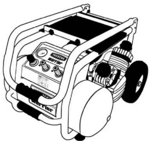
natural_image
Line drawing of a portable air compressor with control panel and wheels (no text or symbols)PREBENA
AEROTAINER 245
VIGON 120
VIGON 240
VIGON 300
WARRIOR 255
WARRIOR 435
PREBENA
Vorwort
EIN-/AUS-Schalter
natural_image
Two identical line drawings of a person handling boxes and documents, no text or symbols present.VIGON 120:
AEROTAINER 245

WARRIOR 255 und WARRIOR 435

WARRIOR 255 WARRIOR 435
natural_image
Line drawings of hands using tools to adjust a mechanical component (no text or symbols present)Ölstand prüfen
natural_image
Illustration of a hand holding a tool next to a car engine cylinder (no text or symbols)This manual will help to ensure
- correct,
- reliable and
- efficient
operation of following compressors:
- AEROTAINER 245
• VIGON 120
• VIGON 240
• VIGON 300 - WARRIOR 255
- WARRIOR 435
In this manual all of them briefly named as "compressors".
We suppose that each compressor's user has knowledges and experience in the use of air compressor plants. The staff which does not have such knowledges before starting work with compressor should be trained under the guidance of skilled user.
This operating manual is intended for those who:
• operate these compressors,
• make cleaning of these compressors,
• utilize these compressors.
Each of these persons should carefully review the content of this manual and fully understand all its provisions.
This operating manual is part of the product. Keep it always near the compressor. Give this manual to the next user in the event that you sell compressor or pass it in any other way for use to another persons.
Contents
Introduction ...... 2
Contents....3
Symbols 4
General symbols....4
Symbols-signs of danger 4
Symbols-signs on possible property damage or environmental damage 4
Safety 5
Intended use....5
Misuse....5
Safety rules to avoid the injury possibility ....5
Safety rules to avoid the explosion possibility....6
Safety rules to avoid the fire possibility....6
Safety rules to avoid the compressor failure....6
Description 7
VIGON 120 Device overview with specifications ....7
VIGON 240 Device overview with specifications ....8
VIGON 300 Device overview with specifications 9
AEROTAINER 245 Device overview with specifications....10
WARRIOR 255 Device overview with specifications....11
WARRIOR 435 Device overview with specifications....12
Delivery set....13
Protective equipment....14
Plates with guidelines on the compressor....14
Data are on the plate with characteristics 15
Preparation of the compressor to start operation....15
Compressor unpacking....15
Compressor gathering....16
Checkup....16
Functional check of the compressor without edge device....17
Control elements: 18
Compressor control....19
After operation....20
Transportation and storage of compressor 21
Transportation 21
Storage....21
Maintenance of compressor 22
The first maintenance in 50 working hours 22
Check the oil level 22
Oil change 22
Drain of condensate moisture....23
Cleaning the casing and external surfaces 24
Cleaning the air filter....24
Compressor test....25
Maintenance intervals....25
Malfunctions 26
Malfunctions 26
Malfunctions overview 26
Ordering of components....27
Disposal of the compressor 27
Address of the manufacturer....28
Warranty....28
Index 29
Notes 32
Symbols
General symbols
Various provisions of operating manual are marked by specific symbols. Hereby you can easily distinguish rather this is normal
text or
- enumeration or
▶ stage of action.

Advices contain additional information, such as for example, specific data, relating to the efficient operation of the compressor.
Symbols-signs of danger
All signs of danger in this operating manual are made on the same model. On the left you will find a symbol that reflects the type of danger. To the right of it you see a signal word indicating the degree of danger. Below there is a description of source of danger and instructions on its prevention.

DANGER
Instructions with the word DANGER warn about threats that directly lead to serious or fatal injuries.

WARNING
Instructions with the word WARNING warn about threats that can lead to serious or fatal injuries.

CAUTION
Instructions with the word CAUTION warn about threats that can lead to injuries of mild and moderate severity.
Symbols-signs on possible property damage or environmental damage
ATTENTION!
These instructions warn about threats that lead to property damage or to environmental damage.
Safety
When you work with compressor pay attention to all warnings and notes in this manual and on compressor and strictly follow all instructions. The attached list of spare parts is a component part of this operating manual.
Intended use
Compressors are used to compressed air supply of following pneumatic equipment:
- edge devices for blasting and cleaning
• edge devices for painting
• hammering devices (for nailing) - other pneumatic equipment for professional and personal use.
Intended use also includes observance of safety rules and working in the field of legal regulations and standards. Any other use is considered as misuse and can lead to property damage or even to injury.
Misuse
Misuse is considered in particular use:
- by persons without knowledge of compressors and their use
• with bridges replacing fuses
• compressors were willfully made any inconsistent changes
• for medical purposes
• as a pulmonary ventilation apparatus.
Limited Company Ltd PREBENA Wilfried Bornemann GmbH & Co. is not be liable for any damage arising from the misuse of the equipment.
Safety rules to avoid the injury possibility
▶ The compressor should be out of reach of children and unqualified staff
▶ Before any movement of the compressor it is necessary to relieve pressure from receiver.
▶ Before any movement of the compressor disconnect the compressor from the voltage source.
▶ Place the compressor so that during operation it could not roll away or tip over.
▶ Switch on the compressor only provided that it is securely placed.
▶ Do not switch on the compressor if connection cable is damaged or connecting to voltage source is unreliable.
▶ Never work in not aired rooms.
Do not touch cylinder head, cooling fins and lines with compressed air, because during the compressor's work these components are heated and remained hot for a long time after switching-off.
▶ Never direct compressed air blast coming out from your edge device on people and animals.
▶ Compressed air hose by opening of quick-split coupling should be kept tight.
By prolonged operation of the compressor, situating in the immediate vicinity from the compressor, wear protective antinoise headphones.
Safety rules to avoid the explosion possibility
▶ Never switch on the compressor with defective safety valve.
▶ Do not expose the compressor to high temperatures, above 100 °C.
▶ Do not operate the compressor in explosion hazard areas and rooms.
▶ Make sure that the compressor is not absorbed flammable, corrosive or toxic gases.
If the pressure in receiver exceeds the maximum rate (see "Technical data" starting from page 7), and the compressor does not switch off automatically:
Switch off the compressor.
▶ Remove the power plug to avoid unpremeditated switching on.
▶ Relieve pressure from receiver.
Safety rules to avoid the fire possibility
▶ Do not operate the compressor close to open fire.
▶ Do not allow piceous items and materials presence close to the compressor.
▶ Make sure that the compressor is not absorbed flammable, corrosive or toxic gases.
Safety rules to avoid the compressor failure
▶ The compressor should never operate without air filter.
▶ Do not hit with metal or sharp items on the working or indicator elements. This can lead to breakage.
▶ Never open the casing of the compressor. Leave all repairs only to qualified service personnel.
▶ Do not use the compressor if it is faulty. Invite qualified maintenance workers to check and repair before restart the compressor.
▶ Make sure that the compressor is not absorbed flammable, corrosive or toxic gases.
▶ Switch off the compressor before pull out the power plug.
▶ Check whether the line voltage correspond to characteristics on the plate.
▶ Never open the casing of the compressor. Leave all repairs only to qualified service personnel of the company PREBENA.
Description
VIGON 120 Device overview with specifications

| No | Explanation |
| 1 | Cylinder head |
| 2 | Compressor screen |
| 3 | Carrying handle |
| 4 | Switch |
| 5 | Pressure relay casing |
| 6 | Pressure reducer |
| 7 | Connection for edge device; quick-split coupling; union nipple (adjustable) |
| 8 | Manometer for pressure measurement in the air receiver |
| 9 | Manometer for operating pressure measurement of edge device |
| 10 | Safety valve |
| 11 | Air receiver |
| 12 | Rubber feet |
| 13 | Water outlet valve (under air receiver) |
| 14 | Air duct |
| 15 | Vent pipe |
| 16 | Plate with characteristics |
| - | Air filter (without picture; behind cylinder head – pos. No 1) |
Specifications of VIGON 120
| Compressor dimensions (L × W × H): | 510 × 240 × 480 mm |
| Compressor weight: | 18 kg |
| Packing box dimensions (L × W × H): | 540 × 260 × 510 mm |
| Weight of the packaging box with contents: | 20 kg |
| Suction power: | 120 l/min |
| Filling speed: | 85 l/min |
| Rated voltage: | 230 – 240 V ~ |
| Power frequency: | 50/60 Hz |
| Electric fuse (inertial): | 16 A |
| Power consumption: | 1100 W |
| Maximum number of revolutions: | 2850/min |
| Tank capacity: | 12 l |
| Oil amount: | 0,13 l |
| Compression pressure: | 8 bar |
| Noise level in accordance with DIN EN ISO 3744 (2000/14/EC): | LWA,1s = 93 dB (A)LPA= 79 dB (A) |
| Ratio: operating time – downtime: | 65:35 |
| Ambient temperature: | From +5 °C to +40 °C |
| Minimum distance from wall: | 50 cm |
| Recommended lubricant: | Special compressor oil PREBENARreference number: 200.40 and Z 200.60 |
VIGON 240 Device overview with specifications

| No | Explanation |
| 1 | Cylinder head |
| 2 | Compressor screen |
| 3 | Compressor casing |
| 4 | Switch |
| 5 | Pressure relay |
| 6 | Manometer for pressure measurement in the air receiver |
| 7 | Carrying handle |
| 8 | Pressure reducer |
| 9 | Manometer for operating pressure measurement of edge device |
| 10 | Safety valve (behind pressure reducer) |
| 11 | Connection for edge device; quick-split coupling; union nipple (adjustable) |
| 12 | Air receiver |
| 13 | Rubber feet |
| 14 | Water outlet valve (under air receiver) |
| 15 | Running wheel |
| 16 | Air duct |
| 17 | Vent pipe |
| 18 | Plate with characteristics |
| - | Air filter (without picture; behind cylinder head – pos. No 1) |
Specifications of VIGON 240
| Compressor dimensions (L × W × H): | 600 × 340 × 570 mm |
| Compressor weight: | 26 kg |
| Packing box dimensions (L × W × H): | 620 × 360 × 590 mm |
| Weight of the packaging box with contents: | 28 kg |
| Suction power: | 240 l/min |
| Filling speed: | 160 l/min |
| Rated voltage: | 230 – 240 V ~ |
| Power frequency: | 50/60 Hz |
| Electric fuse (inertial): | 16 A |
| Power consumption: | 1500 W |
| Maximum number of revolutions: | 2850/ min |
| Tank capacity: | 24 l |
| Oil amount: | 0,25 l |
| Compression pressure: | 8 bar |
| Noise level in accordance with DIN EN ISO 3744 (2000/14/EC): | LWA,1s = 93 dB (A)LPA= 79 dB (A) |
| Ratio: operating time – downtime: | 65:35 |
| Ambient temperature: | From +5 °C to +40 °C |
| Minimum distance from wall: | 50 cm |
| Recommended lubricant: | Special compressor oil PREBENARreference number: 200.40 and Z 200.60 |
VIGON 300 Device overview with specifications

| No | Explanation |
| 1 | Cylinder head |
| 2 | Compressor screen |
| 3 | Compressor casing |
| 4 | Switch |
| 5 | Pressure relay |
| 6 | Manometer for pressure measurement in the air receiver |
| 7 | Carrying handle |
| 8 | Pressure reducer |
| 9 | Manometer for operating pressure measurement of edge device |
| 10 | Safety valve (behind pressure reducer) |
| 11 | Connection for edge device; quick-split coupling; union nipple (adjustable) |
| 12 | Air receiver |
| 13 | Rubber feet |
| 14 | Water outlet valve (under air receiver) |
| 15 | Running wheel |
| 16 | Air duct |
| 17 | Vent pipe |
| 18 | Plate with characteristics |
| - | Air filter (without picture; behind cylinder head – pos. No 1) |
Specifications of VIGON 300
| Compressor dimensions (L × W × H): | 750 × 400 × 700 mm |
| Compressor weight: | 57 kg |
| Packing box dimensions (L × W × H): | 770 × 450 × 700 mm |
| Weight of the packaging box with contents: | 38 kg |
| Suction power: | 300 l/min |
| Filling speed: | 190 l/min |
| Rated voltage: | 230 – 240 V ~ |
| Power frequency: | 50/60 Hz |
| Electric fuse (inertial): | 16 A |
| Power consumption: | 1800 W |
| Maximum number of revolutions: | 2850/ min |
| Tank capacity: | 50 l |
| Oil amount: | 0,50 l |
| Compression pressure: | 9 bar |
| Noise level in accordance with DIN EN ISO 3744 (2000/14/EC): | LWA1s = 95 dB (A) LPA = 85 dB (A) |
| Ratio: operating time – downtime: | 65:35 |
| Ambient temperature: | From +5 °C to +40 °C |
| Minimum distance from wall: | 50 cm |
| Recommended lubricant: | Special compressor oil PREBENAReference number: 200.40 and Z 200.60 |
AEROTAINER 245 Device overview with specifications
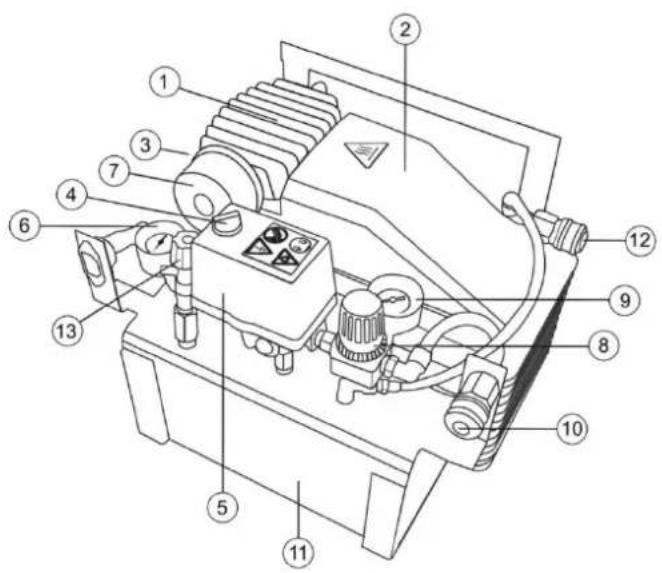
| No | Explanation |
| 1 | Cylinder head |
| 2 | Compressor screen |
| 3 | Compressor casing |
| 4 | Switch |
| 5 | Pressure relay |
| 6 | Manometer for pressure measurement in the air receiver |
| 7 | Air filter |
| 8 | Pressure reducer |
| 9 | Manometer for operating pressure measurement of edge device |
| 10 | Connection for edge device; quick-split coupling; union nipple (adjustable) |
| 11 | Air receiver |
| 12 | Connection for edge device; quick-split coupling; union nipple ( pressure in boiler ) |
| 13 | Water outlet valve (lifting pipe) |
| 14 | Water outlet valve (lifting pipe) |
| - | Air filter ( without picture; behind pressure relay – pos. No 5) |
Specifications of AEROTAINER 245
| Compressor dimensions (L × W × H): | 395 × 295 × 320 mm |
| Compressor weight: | 23,5 kg |
| Packing box dimensions (L × W × H): | 400 × 300 × 325 mm |
| Weight of the packaging box with contents: | 25 kg |
| Suction power: | 200 l/min |
| Filling speed: | 100 l/min |
| Rated voltage: | 230 – 240 V ~ |
| Power frequency: | 50/60 Hz |
| Electric fuse (inertial): | 16 A |
| Power consumption: | 1500 W |
| Maximum number of revolutions: | 2800/ min |
| Tank capacity: | 2 l |
| Oil amount: | 0,25 l |
| Compression pressure: | 8 bar |
| Noise level in accordance with DIN EN ISO 3744 (2000/14/EC): | LWA,1s = 95 dB (A)LPA= 75 dB (A) |
| Ratio: operating time – downtime: | 65:35 |
| Ambient temperature: | From +5 °C to +40 °C |
| Minimum distance from wall: | 50 cm |
| Recommended lubricant: | Special compressor oil PREBENARreference number: 200.40 and Z 200.60 |
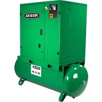
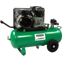
WARRIOR 255 Device overview with specifications

| No | Explanation |
| 1 | Holder |
| 2 | Holder - handle for transportation |
| 3 | Air filter |
| 4 | Cylinder head |
| 5 | Running wheel |
| 6 | Oil filler cap |
| 7 | Oil sight glass |
| 8 | Circuit braker |
| 9 | Air receiver |
| 10 | Rubber feet |
| 11 | Drain cock (under air receiver) |
| 12 | Carrying handle |
| 13 | Lock - handle for transportation |
| 14 | Manometer for pressure measurement in the air receiver |
| 15 | Manometer for operating pressure measurement of edge device |
| 16 | Connection for edge device; quick-split coupling; union nipple (adjustable) |
| 17 | Plate with characteristics |
| 18 | Pressure reducer |
| 19 | Safety valve |
| 20 | Pressure switch |
| 21 | Switch |
Specifications of WARRIOR 255
| Compressor dimensions (L × W × H): | 770 × 530 × 580 mm |
| Compressor weight: | 45 kg |
| Packing box dimensions (L × W × H): | 790 × 550 × 600 mm |
| Weight of the packaging box with contents: | 48 kg |
| Suction power: | 256 l/min |
| Filling speed: | 150 l/min |
| Rated voltage: | 230 – 240 V ~ |
| Power frequency: | 50/60 Hz |
| Electric fuse (inertial): | 16 A |
| Power consumption: | 1840 W |
| Maximum number of revolutions: | 2840/ min |
| Tank capacity: | 20 l |
| Oil amount: | 0,30 l |
| Compression pressure: | 10 bar |
| Noise level in accordance with DIN EN ISO 3744 (2000/14/EC): | LWA,1s = 80 dB (A)LPA= 76 dB (A) |
| Ratio: operating time – downtime: | 65:35 |
| Ambient temperature: | From +5 °C to +40 °C |
| Minimum distance from wall: | 50 cm |
| Recommended lubricant: | Special compressor oil PREBENARreference number: 200.40 and Z 200.60 |
WARRIOR 435 Device overview with specifications
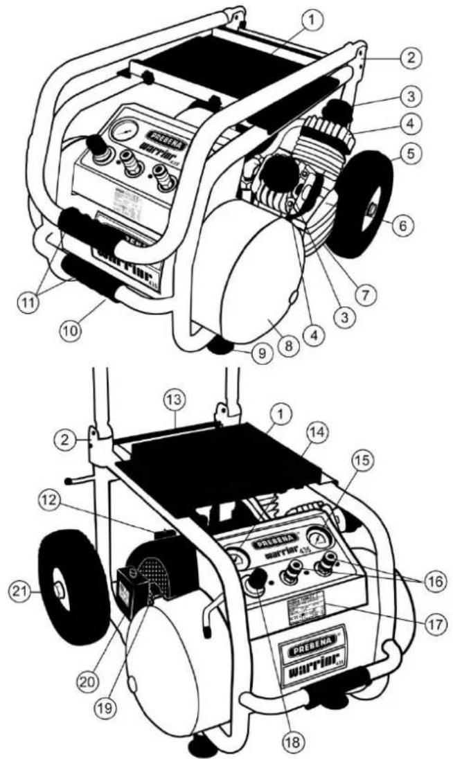
| No | Explanation |
| 1 | Holder |
| 2 | Holder - handle for transportation |
| 3 | Air filter |
| 4 | Cylinder head |
| 5 | Running wheel |
| 6 | Oil filler cap |
| 7 | Oil sight glass |
| 8 | Air receiver |
| 9 | Rubber feet |
| 10 | Drain cock (under air receiver) |
| 11 | Carrying handle |
| 12 | Circuit braker |
| 13 | Lock - handle for transportation |
| 14 | Manometer for pressure measurement in the air receiver |
| 15 | Manometer for operating pressure measurement of edge device |
| 16 | Connection for edge device; quick-split coupling; union nipple (adjustable) |
| 17 | Plate with characteristics |
| 18 | Pressure reducer |
| 19 | Safety valve |
| 20 | Pressure switch |
| 21 | Switch |
Specifications of WARRIOR 435
| Compressor dimensions (L × W × H): | 790 × 630 × 580 mm |
| Compressor weight: | 58 kg |
| Packing box dimensions (L × W × H): | 810 × 650 × 600 mm |
| Weight of the packaging box with contents: | 61 kg |
| Suction power: | 433 l/min |
| Filling speed: | 210 l/min |
| Rated voltage: | 230 – 240 V ~ |
| Power frequency: | 50/60 Hz |
| Electric fuse (inertial): | 16 A |
| Power consumption: | 2200 W |
| Maximum number of revolutions: | 2840 U/min |
| Tank capacity: | 25 l |
| Oil amount: | 0,32 l |
| Compression pressure: | 10 bar |
| Noise level in accordance with DIN EN ISO 3744 (2000/14/EC): | LWA.1s = 80 dB (A)LPA= 75 dB (A) |
| Ratio: operating time – downtime: | 65:35 |
| Ambient temperature: | +5 °C bis +40 °C |
| Minimum distance from wall: | 50 cm |
| Recommended lubricant: | Special compressor oil PREBENARreference number: 200.40 and Z 200.60 |
Delivery set
VIGON 120
- compressor
- 1 air filter
• 1 oil-filling hole plug - operating manual
- conformance certificate
VIGON 240 and VIGON 300
- compressor
- 2 running wheels with bolts and mounting screws
- 1 air filter
• 1 oil-filling hole plug - operating manual
- conformance certificate
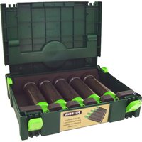
AEROTAINER 245, WARRIOR 255 und WARRIOR 435
- compressor
- operating manual
• conformance certificate
Principle of operation
Compressors are reciprocating compressors with oil lubricant and are used for the generation of compressed air and accumulation of compressed air to the corresponding maximum pressure. Excess pressure is discharged through the safety valve. Compressed air is used to supply pneumatic equipment running on compressed air, for professional and personal use.
Distinguishing characters of compressors:
Compressors have the following common features:
• Electric-driven compressors for professional and personal use
- Safety valve
• Automatic starting and shutdown system of pressure relay
• Automatic motor breaker
• Power supply 230 V
Types of compressors differ in the following parameters:
VIGON 120
• Air receiver with volume 12 l
- Total weight 18 kg
- Carrying handle
• Max. pressure 8 bar
VIGON 240
• Air receiver with volume 24 l
- Total weight 26 kg
- Runners
- Dragging handle
• Max. pressure 8 bar
VIGON 300
• Air receiver with volume 50 l
• Total weight 35 kg
- Pneumatic wheels
- Dragging handle
• Max. pressure 9 bar
AEROTAINER 240
• Air receiver with volume 2 l
• Total weight 23,5 kg
• In container Systainer Max. pressure 8 bar
WARRIOR 255
• Air receiver with volume 20 l
• Total weight 45 kg
- Pneumatic wheels
- Carrying handle
• Max. pressure 10 bar
- Holder for drum
WARRIOR 435
• Air receiver with volume 25 l
• Total weight 58 kg
- Pneumatic wheels
- Carrying handle
• Max. pressure 10 bar
- Holder for drum
Protective equipment
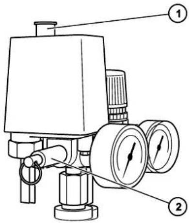
Switch
Compressors are equipped with a switch (1), which can also be used as an emergency switch.
- Position I: ON.
- Position 0: OFF.
Safety valve
Safety valve (2) is activated when the maximum allowable pressure in the air receiver is exceeded by 10%.
Automatic motor breaker
Compressors serially have an internal automatic motor breaker. Compressors WARRIOR 255 and WARRIOR 435 are equipped with external automatic motor breaker. Positioning an external automatic motor breaker marked with special plate. When faults appear (e.g, by overheating, etc.) motor protection is activated and stops the power supply. In this case see malfunctions overview on page 26, p.G.
Plates with guidelines on the compressor
There is sticker with four icons on pressure relay. They have the following meanings:
Sticker

Meaning
Positions picture of pressure relay:
• I = ON
- 0 = OFF

Warning on possibility of electric shock
Sticker

Meaning
Inhibition: do not pull the plug until the compressor is switched off.

Warning on rotating components by automatic startup.
There are more icons near or at the compressor casing. They have the following meanings:
Sticker

Meaning
Before compressor commissioning it is necessary to be familiar with operating manual.
Sticker

Meaning
Warning on hot surfaces.

Guaranteed sound-power level data for this machine.
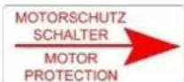
Indicates the position of an external automatic motor breaker.
Data are on the plate with characteristics
Plate with characteristics is pasted on compressor casing. It contains the following data:
Plate with compressor characteristics
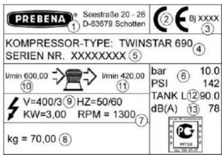
| No | Explanation |
| 1 | Company name, address and country of origin |
| 2 | The CE mark (product meets regulatory requirements specified in the attached conformance certificate). |
| 3 | Year of production |
| 4 | Type designation / motor type designation |
| 5 | Serial number |
| 6 | Maximum pressure [bar] and [ihp] |
| 7 | Number of unit revolutions / number of motor revolutions |
| 8 | Total weight |
| 9 | Power characteristics |
| 10 | Suction power |
| 11 | Filling speed |
| 12 | Volume of air receiver |
| 13 | Acoustic noise release |
Preparation of the compressor to start operation
Compressor unpacking
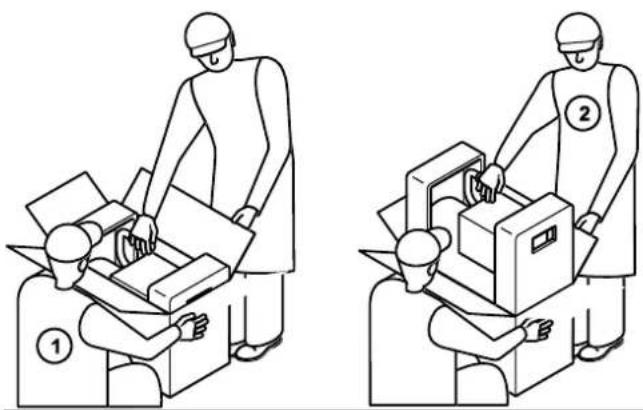
Compressor unpacking is carried out by two workers.
natural_image
Two identical line drawings of a person operating a cart, labeled ① and ② (no text or symbols on the figures themselves)▶ Place the box in front of you.
▶ Open the top cover of the box.
▶ Hold tight the box by carrying holes (1).
▶ Carefully remove the compressor from package (2) and place it in front of you.
▶ Remove all packaging material from compressor.

WARNING
Do not allow children to play with the packaging film, there is a danger of suffocation.
▶ Do not allow children to play with the packaging film.
▶ Packing material keep out of children's reach.
Save the packing material.
Compressor gathering
Some components are supplied separately in package and they are not installed on the compressor.
VIGON 120:
- oil-filling hole plug (2)
• air filter (3)
VIGON 240:
- running wheels with axes and screw nuts (1)
- oil-filling hole plug (2)
• air filter (3)
VIGON 300:
- running wheels with ax-es and screw nuts (1)
- air filter (3)

VIGON 120:
▶ Fix air filter (3), screw it manually on the cylinder head.
▶ Remove transport plug of oil-filling hole.
▶ Set the plug (2) on the neck of oil tank by turning it.
VIGON 240:
▶ Put axes into holes on the smooth side of running wheels (1).
▶ Fix axes from the side of tail bearings (nut with the key 17).
▶ Fix air filter (3), screw it manually on the cylinder head.
▶ Remove transport plug of oil-filling hole.
▶ Set the plug (2) on the neck of oil tank by turning it.
VIGON 300:
▶ Put axes into holes on the smooth side of running wheels (1).
▶ Fix axes from the side of tail bearings (nut with the key 17).
▶ Fix air filter (3), screw it manually on the cylinder head.
Checkup

WARNING
Risk of accidents by using faulty compressor.
▶ Check condition of the compressor before each use.
▶ Make sure that the compressor is in perfect condition.
▶ In particular check the following:
- If the safety valve is faultless?
- If the air filter is set on the cylinder head?
- If running wheels are set on types VIGON 240 and VGON 300?
- If the oil level is enough?
- If the connection to power supply is in order?

Scratches on the casing are not a failure.
▶ Do not connect faulty compressor to the power supply.
Before starting the operation of the compressor refer to employees of company PREBENA so they carry out the repair.

WARILY
Damaged pressure lines can be broken, it lead to injury.
▶ Before connecting check the compressor and pressure lines on damages.
ATTENTION!
Damaged pressure lines can be broken and the stream of compressed air-out can inflict property damage.
▶ Before connecting check the compressor and pressure lines on damages.
Functional check of the compressor without edge device
To ensure a faultless work of the compressor by first starting proceed as follows:
▶ Operate the compressor only in cool, dust-free, dry and well ventilated rooms.
The ambient temperature should not be below 5 °C and above +40 °C.
The slope of bearing surface in across-track and longitudinal directions should not be greater than 15 degrees to avoid damages of the compressor.
▶ Make sure that the minimum distance is complied between the compressor and any possible obstacle to air flow is 50 cm.
Before starting make sure that voltage and supply frequency correspond to data on the plate with characteristics of the compressor.
ATTENTION!
Operation with power supply with out following above conditions can lead to compressor damage.
▶ Connect the compressor only to appropriate power supply.
ATTENTION!
▶ Pay attention to instructions about possible dangers in the chapter "Safety" beginning from page 5.
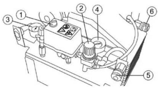
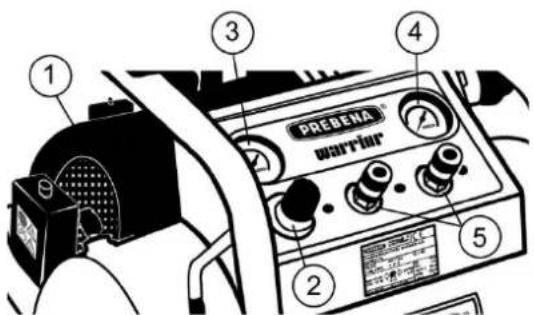
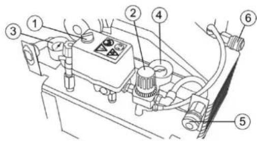
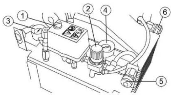
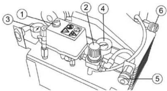
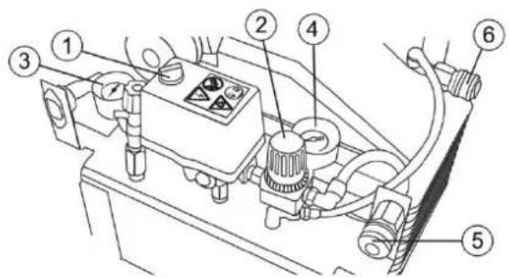
Control elements:
VIGON 100, VIGON 240, VIGON 300, ORKAN 215, PIONEER 282 and PIONEER 342

AEROTAINER 240

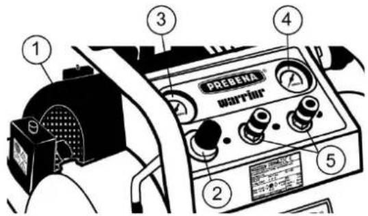
WARRIOR 255 and WARRIOR 435

No Explanation
1 Switch
2 Pressure reducer
3 Manometer for pressure measurement in the air receiver
4 Manometer for operating pressure measurement of edge device
5 Union nipple for edge device (adjustable)
No Explanation
1 Switch
2 Pressure reducer
3 Manometer for pressure measurement in the air receiver
4 Manometer for operating pressure measurement of edge device
5 Union nipple for edge device (adjustable)
6 Union nipple for edge device (pressure in boiler)
No Explanation
1 Switch
2 Pressure reducer
3 Manometer for pressure measurement in the air receiver
4 Manometer for operating pressure measurement of edge device
5 Union nipple for edge device (adjustable)
▶ Connect the compressor to the power supply.
Extension cables should have a cross section minimum 2.5 mm2 and can have length maximum 30 m.
Turn the pressure reducer (2) by turning it counterclockwise.
▶ Switch on the compressor using the switch (1) to start it.
▶ Let the compressor run for approximately 10 minutes without load.
▶ In this case check the following points:
- If pressure rises in the air receiver? You can see it on manometer (3)
- If the compressor switches off automatically by achievement of maximum pressure? (see technical specifications, starting from page 7)
Maximum allowable operating pressure produced by the compressor is limited automatically by the pressure relay. Safety valve limits additionally the pressure rise above 10% of maximum allowable.

WARNING
Explosion risk by excess of the maximum allowable operating pressure.
▶ Never make any actions with the safety valve.
When pressure is restored and the compressor is switched off by achievement of maximum pressure (see technical specifications, starting from page 7), the compressor is ready for operation.
▶ Switch off the compressor using the switch (1).
▶ Release condensate as described on page 23.
ATTENTION!
Condensate is a harmful substance that is hazardous to environment.
▶ Place an appropriate container under drainage hole.
▶ Spilled condensate to be immobilized by using a binder.
▶ Immobilized condensate remove with a rag.
▶ Utilize a rag in accordance with applicable legal requirements of the application place.
Compressor control
For compressor control, proceed as follows:
VIGON 120 VIGON 240
VIGON 300

AEROTAINER 245
WARRIOR 255 WARRIOR 435

▶ Prepare the compressor as described above, starting from page 15.
▶ Switch on pressure reducer (2) by turning it counterclockwise.
▶ Define allowable operating pressure of your edge device (pneumatic staple gun, painting gun, pneumatic device for nailing, etc.)

WARNING
Explosion risk by excess of the maximum allowable operating pressure.
▶ Define characteristics of your edge device before compressor connecting.
- Connect pressure hose of edge device to the union nipple (5) with reduced or (6) pressure of the boiler.
- Raise button (1) of pressure relay to start the compressor.
▶ Wait until manometer (3) will not show the maximum operating pressure of appropriate compressor. Set the allowable operating pressure of your edge device on pressure reducer (2).
- Turn clockwise increases pressure.
- Turn counterclockwise lowers pressure.

Turn of reducer on 90° changes operating pressure on about 0.5 bar
Operating pressure of edge device is reflected on the manometer (4).
The compressor starts automatically again as soon as pressure in the receiver falls after relief to starting pressure (6-7 bar). This process is controlled automatically by pressure relay.
ATTENTION!
In case of overload the compressor can be damaged.
Do not overload the compressor: Do not exceed the ratio of operating time and downtime! See the technical specifications, starting from page 7.
After operation
After operation or long break in operation proceed as follows.
To disconnect from compressed air supply proceed as follows:
▶ Switch off the compressor using the switch (1).
▶ Disconnect the compressor from power supply.
▶ Disconnect connected pressure hose from the quick-split coupling.

DANGER
In case of opening of union nipple a freely suspended pressure hose can cause severe or fatal injuries.
▶ Secure firmly pressure hose.
Proceed as follows:
▶ Press union nipple of pressure hose to the quick-split coupling
▶ Move the external O-ring of quick-split coupling backwards Quick-split connection is unlocked.
▶ Remove pressure hose from the quick-split coupling.
In this case you will hear leftover compressed air in the edge device goes out.
- Drain the remaining compressed air from receiver through the drain valve.
Transportation and storage of compressor
Packaging
Before shipment for storage or before transportation for a long-distance, pack compressor in the original packaging, especially when moving at a distance:
- More that 10 m
• over uneven surfaces.
To do this, perform the following preparatory actions:
▶ Follow the actions described on page 20 "After operation".
▶ Clean the connections for compressed air supply from foreign bodies and dirt.
▶ Pack compressor in the original packaging.
Transportation
Type of transportation varies depending on the compressor moves for short or long distances.
Transportation for short distances
Short distances it is maximum 10 m
▶ Follow the actions described on page 20 "After operation".
ATTENTION!
Shocks or strikes can damage the compressor.
▶ Avoid dropping the compressor.
▶ Avoid striking the compressor on the obstacles.
If it is a transferable compressor: when moving, then hold the compressor for the handle, so it does not tip over.
VIGON 120
AEROTAINER 245
Move the compressor taking it at the handle to a new place of work.
▶ Connect the edge device to the compressor only at the new place of work.
VIGON 240
VIGON 300
WARRIOR 255
WARRIOR 435
Move the compressor taking it at the handle to a new place of work.
▶ Connect the edge device to the compressor only at the new place of work.
Transportation for long distances
The following distances are long for the compressor transportation:
• distances more than 10 m,
• distances over uneven surfaces and
- moving in unusual position

Transportation of compressor over long distances is allowed only in the original box.
For transportation of compressor over long distances, proceed as follows:
▶ Follow the actions described on page 20 "After operation".
▶ Pack the compressor in the original box in which it was delivered.
▶ Move to the necessary place of work in its original packaging, holding the two holes for lifting.
▶ Place the original box just straight the lid up.
Storage
▶ Lubricate all metal parts of the compressor with a thin layer of special oil Prebena.
▶ Pack the compressor in the original box.
▶ Store the compressor at room temperature in a dry and dust-free place.
Maintenance of compressor
To maintain the compressor in perfect condition it is necessary to perform some periodic works on its maintenance.
i
Compressor maintenance should be carried out only by professionals with the necessary knowledge, skills and experience. All works witch are not described here can also be performed only by specialist of department of work with clients of the enterprise-manufacturer or of manufacturer service center.
Before performing any maintenance disconnect the compressor and bleed air from the receiver.
▶ Disconnect the compressor from the power supply to avoid unintended inclusion.
The first maintenance in 50 working hours

natural_image
Technical line drawing showing two hands operating a mechanical component (no text or symbols present)Check the oil level
The oil level can be checked through the viewing window of the oil tank (1) or by oil dipstick (4), which are located at the rear end of the compressor. The oil level should be in the interval (3) between the minimum and maximum value.

Oil change
i
Oil change should be made with a warm compressor. Then the oil tank is emptied quickly and completely.

CAUTION
Danger of fire of hot oil
▶ Wear appropriate protective gloves.
WARNING!
Spill of lubricating oil can cause a serious harm to the environment.
▶ To immobilize spilled oil using a binder.
▶ To collect immobilized oil with a rag.
▶ To utilize the rag in accordance with applicable legal requirements of the application site.
▶ Place a container to collect the oil under compressor.
Remove the plug of oil tank inspection opening (1) or the screw of oil discharge hole (5) so that the old oil run out.
▶ Tilt the compressor so that the old oil run out from the compressor without a trace.
▶ Check if it is necessary to replace the sealant on the oil tank inspection hole (1) or the screw of oil discharge hole (5).
▶ Again tight the plug of oil tank inspection opening (1) or the screw of oil discharge hole (5).
Remove the plug of oil discharge hole and oil dipstick and fill new oil with a suitable hopper (2).
When the compressor operates at a temperature of 10\ °C to 40\ °C use a special oil Prebena Z200.40, and at a temperature below 10\ °C use oil Prebena with good antifriction properties Z200.60.
▶ Check the oil level at the marking ring (3) or at the oil gage (4)
ATTENTION!
Compressor damage due to use of improper, contaminated or mixed lubricants.
When the compressor operates at a temperature below 10 ° C use only a special oil Prebena Z200.40 or the oil Prebena with good antifriction properties Z200.60.
▶ Do not use inappropriate or contaminated lubricating oil.
▶ Do not mix different varieties of oils.
▶ Dispose of used lubricating oil without damaging the environment.
Drain of condensate moisture
Drain of condensate moisture from the high-pressure receiver
Condensing moisture (condensate) is collecting on the bottom of the receiver. The volume of condensate depends on the load of compressor and on the temperature of environment around compressor.
▶ Drain condensate after each use:
In order to be able to drain the condensate, the pressure in the receiver must be 2-3 bar.
ATTANTION!
Condensate is a harmful substance. It represents a threat to the environment.
▶ Place a suitable container under the drain hole.
▶ To immobilize spilled condensate using a binder.
▶ To collect immobilized condensate with a rag.
▶ To utilize the rag in accordance with applicable legal requirements of the application site.
To drain condensate, proceed as follows:
▶ Place a suitable container under the drain hole.
▶ Open the drain hole for condensate drain, slightly turning its plug counter-clockwise on the lower side of the high pressure receiver.
After a successful condensate drain close the plug again.
Cleaning the casing and external surfaces
WARNING!
Damage of compressor or its components due to the use of unsuitable cleanser.
For cleaning use only dry, slightly dampened duster or the duster soaked in a mild soap solution.
Light contamination
▶ Clean the compressor casing with a dry duster.
▶ Lubricate all metal parts of the compressor with a thin layer of special oil Prebena.
Strong contamination
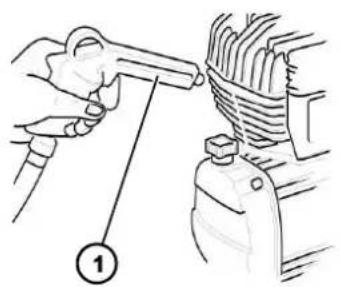
natural_image
Illustration of a hand using a tool to adjust or install a mechanical component, with no visible text or symbols.- Connect the air gun to the compressor (1) and clean all ribbed parts with compressed air.
▶ Clean the compressor casing using a duster slightly dampened in a mild soap solution.
▶ Finally wipe the casing using a duster slightly dampened in tap water.
▶ Completely wipe with a dry, soft duster.
▶ Lubricate all metal parts of the compressor with a thin layer of special oil Prebena.
Cleaning the air filter
Effective cleaning of absorbing air is one of the most important conditions for long compressor life.
WARNING!
Compressor damage due to ingress foreign objects into the suction hole.
▶ The compressor must not be running without the air filter.
▶ Do not blow the suction hole using the air gun. Foreign objects can come into the hole.
VIGON 120, VIGON 240, VIGON 300, WARRIOR 255 und WARRIOR 435
To clean the air filter, proceed as follows:
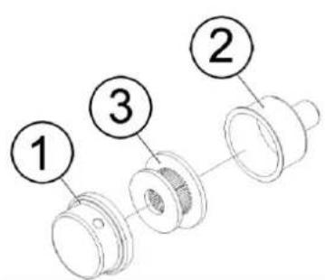
▶ Turn the cover (1) of air filter counter-clockwise. The cover is unlocked.
▶ Remove the cover (1) from the air filter casing (2).
▶ Remove the filter bush (3) and clean it using an air gun. If necessary, replace the filter bush.
▶ Insert the filter bush (3).
▶ Put the cover (1) on the air filter casing (2).
▶ Block the cover by turning it clockwise.
AEROTAINER 245
To clean the air filter, proceed as follows:

▶ Remove the air filter (1) from the connecting thread of the cylinder head (2).
▶ Replace used air filter (1) by a new one.
▶ With an arm effort tighten the new air filter (1) in the connecting thread of the cylinder head (2).
Compressor test
The prototype test was made for this compressor or this is not required if before the commissioning an expert monitoring is not required. We recommend checking receiver under pressure, depending on the load of compressor, after 10 operating years, with the assistance of a qualified worker. A qualified worker is competent to carry out works in accordance with the Regulation on Safety at Work place (formerly - the competent specialist). Please refer to our authorized partners providing the services. They can provide workers who have passed the expert examination.
i
These requirements apply only to the Federal Republic of Germany. The relevant national guidelines are applicable for all other countries. The supplied documentation (= documents for admission) is needed to be kept during the whole period of the receiver life.
Maintenance intervals
| Service work | Every week | Every month | Every 6 month | Every two years |
| Check oil level and add oil if necessary | X | |||
| Drain the condensate water from the high pressure receiver | X | |||
| Clean the air filter | X | |||
| General cleaning of compressor | X | |||
| Oil change | X | |||
| Check the operation of reverse pneumatic valve | X |
Malfunctions

WARNING
Operation of damaged or defective compressor can cause serious or fatal injuries.
▶ When a malfunction occurs immediately disconnect the compressor from the power supply.
▶ Use the compressor only after fault removal.
WARNING!
Implementation of repair by unskilled workers can damage the compressor.
▶ Ensure the repair of compressor is realized only by representatives of the manufacturer.
Malfunctions
When malfunction of compressor appear that you can not eliminate by lubricating and cleaning, you should contact the Service Center of company Prebena.
▶ Do not perform any repair works with compressor on your own.
▶ Ensure removal of any faults of compressor by workers the Service Center of company Prebena.
Malfunctions overview
The following overview shows possible malfunctions and the necessary measures to eliminate them.
| Malfunction | Possible reason | Solution | |
| A | Pressure drop in the receiver | Air outflow through the pipeline and receiver connections | ► Bring the compressor to maximum pressure.► Turn off the compressor.► Disconnect from the mains.► All connections to be greased with a brush dampened in soap solution.Air bubbles will show the place of the air outflow.► These connections to be firmly tightened.► If the air continues to enter, contact the service department (see page 28). |
| B | Air outlet from the pressure relay valve when the compressor does not operate | Leakage of reverse pneumatic valve | ► Relieve air from the receiver.► Remove the cap of reverse pneumatic valve.► Thoroughly clean the valve seat.► If necessary, replace the sealing element.► Set everything back. |
| C | Air outlet from the pressure relay valve if the compressor is running more than 1 minute | Faulty idle running valve | ► Change idle running valve. |
| D | The compressor is turned off and does not run anymore | The motor protective breaker is activated due to a malfunction (overheating, low voltage, an extension cable is too long or has the wrong section) | ► Interrupt flow of current through the pressure relay.► Let the compressor cool down.► In compressors with an external motor protective breaker: activate it.If with a new start the motor protective breaker is activated again: E► Contact the service department (see page 28). |
| E | After the maximum pressure is reached and the compressor is not turned off, the safety valve does not work. | Disturbance of function or faulty pressure relay. | ► Turn off the compressor.► Contact the service department (see page 28). |
| F | The compressor is turned off and does not run anymore | The motor winding is burned out. | ► Contact the service department (see page 28). |
Ordering of components
You can order components from the manufacturer (see page 28). Use only original components Prebena or components of enterprises witch have access to Prebena for use with these compressors.
Ordering of additional components
All Types
| Артикул No | Components |
| Z 200.40 | Special oil PREBENA |
| Z 200.60 | Lubricating oil with good antifriction properties PREBENAI |
| Z200.25 | Set of hoses 6 x 3 mm (10 m) |
| Z200.20 | Set of hoses 9 x 3 mm (10 m) |
| Z180.00 | Drum for winding the hose for compressed air, 30 m, hose for compressed air 8 x 12 mm |
| Z160.11 | Spiral hose 6 x 9 mm |
| Z160.12 | Spiral hose 9 x 12 mm |
| Z140.42B | Air distributor 2 branches |
| Z140.44B | Air distributor 3 branches |
| Z170.80B | Air gun from light alloy metal with a connecting nipple |
| Z175.80 | Gun for tyre pumping with kit of adapters |
Additional components you can find on www.prebena.de
Disposal of the compressor
ATTANTION
▶ Risk of harm to the environment when disposing of environmentally inappropriate way.
▶ Clean compressor before disposal.
▶ Adhere to existing regulations on the disposal of oil.


Under no circumstances throw the compressor or its components in the normal household refuse. If you want to recycle compressor, send it to the company Prebena. The company Prebena will carry out a proper disposal of the compressor. Contact details can be found on page 28.
Address of the manufacturer
Limited Company Ltd Prebena
For the described device company Prebena provides 1 year warranty from date of sale in accordance with the following warranty conditions. Prebena Company guarantees free removal of malfunctions associated with defects of materials or manufacture. Violations of function or malfunction associated with the incompetent use within the free warranty shall be disregarded.
In addition, you should use only original mounting technique of company Prebena, in case of non-compliance of this condition warranty from the manufacturer does not work, and thus warranty requirements are not possible. The warranty does not cover consumables, such as, for example, o-rings, etc. The company Prebena has the right in its sole discretion to decide the question of providing warranties in the form of replacement of defective components or the provision of other compressor. Submission of other claims is impossible.
For presentation of the claim to execute guarantees it is necessary to present a fully completed warranty card stamped by the seller and with the date of sale, or supporting document attached to a bill which contains the dates and details in accordance with the warranty card.
Shipping: defective device must be carefully packaged and sent to the address of company Prebena with postal charge prepaid.

The warranty card
| Model: | Date of purchase: |
| Seller: | (stamp) |
Index
A
Address of the manufacturer 28
C
CE-mark 15
Check
Functional check 17
Checkup 16
Cleaning
Air filter 24
Casing and external surfaces 24
Light contamination 24
Strong contamination 24
Compressor
Dispose 27
Gathering 16
Maintenance 22
Storage 21
Compressor control 19
Compressor test 25
Contamination
Light 24
Strong 24
Contents 3
Control
Distinguishing characters 13
Function 13
Description 7
Device overview
AEROTAINER 245 10
VIGON 120 7
VIGON 240 8
VIGON 300 9
WARRIOR 255 11
WARRIOR 435 12
Dispose 27
Drain of condensate moisture 23
F
Functional check 17
G
Gathering 16
|
Index 29
Injury
Avoid 5
Protective equipment 5
Intended use 5
Misuse 5
L
Long distances 21
M
Maintenance 22
Cleaning the air filter 24
Drain of condensate moisture from the high-
pressure receiver 23
intervals 25
Oil change 22
Malfunctions 26
Malfunctions overview 26
Malfunctions solution 26
motor breaker 14
N
Notes 32
0
Oil change 22
Operation
After operation 20
Malfunctions solution 26
Ordering of components 27
P
Plate with characteristics 15
Plates with guidelines 14
Preparation
Checkup 16
Preparation of the compressor 15
Principle of operation 13
s
Safety
Basic instructions 5
motor breaker 14
Plates with guidelines 14
Switch 14
Safety rules to avoid the explosion possibility 6
Safety rules to avoid the fire possibility 6
Service department 28
Short distances 21
Specifications
AEROTAINER 245 10
VIGON 120 7
VIGON 240 8
VIGON 300 9
WARRIOR 255 11
WARRIOR 435 12
Storage 21
Storage 21
Switch 14
Symbols 4
T
Transportation
Long distances 21
Short distances 21
Transportation 21
Troubleshooting 26
U
Unpacking 15
W
Warranty 28
Préface
Interrupteur
• I = BRANCHÉ
• 0 = DÉBRANCHÉ

VIGON 120:
AEROTAINER 245

WARRIOR 255 et WARRIOR 435


WARRIOR 255 WARRIOR 435

Transport aux longes distances
natural_image
Technical line drawings showing hands operating a mechanical component (no text or symbols present)natural_image
Illustration of a hand using a tool to adjust or install a vehicle engine component (no text or symbols present)Wyłącznik
• I = WL.
• 0 = WYŁAĆŻ.

natural_image
Two identical line drawings of a person operating a cart, labeled ① and ② (no text or symbols on the figures themselves)VIGON 120:
AEROTAINER 245

WARRIOR 255 i WARRIOR 435


WARRIOR 255 WARRIOR 435

natural_image
Line drawings of two hands operating a mechanical component, one holding a tool and the other adjusting a workpiece (no text or symbols present)natural_image
Illustration of a hand using a tool to adjust or install a mechanical component, with no visible text or symbols.
Interruptor
natural_image
Two identical line drawings of a person handling boxes and equipment, labeled 1 and 2 (no text or symbols on the figures themselves)VIGON 120:
AEROTAINER 245

WARRIOR 255 e WARRIOR 435

WARRIOR 255 e WARRIOR 435
natural_image
Line drawings showing hands using a wrench to adjust the engine component (no text or symbols present)Διακόπτης
natural_image
Line drawing of two people handling documents or files, one standing and one seated (no text or symbols)
natural_image
Illustration of a person handling a cardboard box with a numbered badge (no text or symbols present)VIGON 120:
AEROTAINER 245
WARRIOR 255 kai WARRIOR 435


WARRIOR 255 WARRIOR 435

natural_image
Technical line drawing showing two mechanical assembly steps: one with a tool and the other with a handle (no text or symbols)Spínač ZAP/VYP
natural_image
Two identical line drawings of a person handling boxes, no text or symbols presentVIGON 120:
AEROTAINER 245

WARRIOR 255 a WARRIOR 435

AEROTAINER 245
WARRIOR 255 WARRIOR 435

natural_image
Line drawings of hands operating a mechanical component, showing two different states (no text or symbols present)natural_image
Illustration of a hand using a tool to adjust or install a mechanical component, with no visible text or symbols.
- PREBENA
- Vorwort
- EIN-/AUS-Schalter
- VIGON 120:
- Ölstand prüfen
- Contents
- Symbols
- General symbols
- Symbols-signs of danger
- DANGER
- WARNING
- CAUTION
- Symbols-signs on possible property damage or environmental damage
- ATTENTION!
- Safety
- Intended use
- Misuse
- Safety rules to avoid the injury possibility
- Safety rules to avoid the explosion possibility
- Safety rules to avoid the fire possibility
- Safety rules to avoid the compressor failure
- Description
- VIGON 300 Device overview with specifications
- AEROTAINER 245 Device overview with specifications
- Delivery set
- VIGON 120
- VIGON 240 and VIGON 300
- AEROTAINER 245, WARRIOR 255 und WARRIOR 435
- Principle of operation
- Distinguishing characters of compressors:
- VIGON 240
- VIGON 300
- AEROTAINER 240
- WARRIOR 255
- WARRIOR 435
- Protective equipment
- Switch
- Safety valve
- Automatic motor breaker
- Plates with guidelines on the compressor
- Meaning
- Preparation of the compressor to start operation
- Compressor unpacking
- Compressor gathering
- VIGON 240:
- VIGON 300:
- Checkup
- WARILY
- Functional check of the compressor without edge device
- Control elements:
- No Explanation
- Compressor control
- After operation
- Proceed as follows:
- Transportation and storage of compressor
- Packaging
- Transportation
- Transportation for short distances
- AEROTAINER 245
- Transportation for long distances
- Storage
- Maintenance of compressor
- i
- The first maintenance in 50 working hours
- Check the oil level
- Oil change
- WARNING!
- Drain of condensate moisture
- Drain of condensate moisture from the high-pressure receiver
- ATTANTION!
- Cleaning the casing and external surfaces
- Light contamination
- Strong contamination
- Cleaning the air filter
- VIGON 120, VIGON 240, VIGON 300, WARRIOR 255 und WARRIOR 435
- Compressor test
- Malfunctions
- Malfunctions overview
- Ordering of components
- Ordering of additional components
- Disposal of the compressor
- ATTANTION
- Address of the manufacturer
- Limited Company Ltd Prebena
- Index
- A
- C
- F
- G
- |
- L
- M
- N
- 0
- P
- s
- Specifications
- T
- U
- W
- Préface
- Interrupteur
- Transport aux longes distances
- Wyłącznik
- Interruptor
- Διακόπτης
- Spínač ZAP/VYP
Brand : Prebena
Model : WARRIOR 255
Category : Compressor