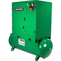
SK 15-10 - Compressor Prebena - Free user manual and instructions
Find the device manual for free SK 15-10 Prebena in PDF.


| Brand | Prebena |
| Model | SK 15-10 |
| Product type | Screw compressor |
| Delivery rate | 1900 l/min |
| Maximum working pressure | 10 bar (adjustable) |
| Mains voltage | 400 V three-phase |
| Mains frequency | 50 Hz |
| Recommended fuse | 29.3 A (time-delay) |
| Power consumption | 15000 W (15 kW) |
| Max speed | 6060 rpm |
| Tank capacity | 500 liters |
| Oil quantity | 5.5 liters |
| Noise level (LpA) | 77 dB(A) |
| Operating temperature | +5 °C to +40 °C |
| Minimum wall distance | 50 cm |
| Recommended lubricant | PREBENA Special synthetic oil (ref. Z200.80) |
| Control type | Electronic controller AirMaster P1 |
| Main functions | Compressed air production for pneumatic tools, automatic control with standby and idle modes, temperature and pressure monitoring |
| Routine maintenance | Oil change every 4000 h, air filter replacement every 500 h, oil filter and separator every 4000 h |
| Safety | Safety valve, emergency stop, thermal protection, phase relay, circuit breaker |
| Spare parts available | Filters, separator, belts, seals, oil, safety valve from Prebena |
Frequently Asked Questions - SK 15-10 Prebena
User questions about SK 15-10 Prebena
0 question about this device. Answer the ones you know or ask your own.
Ask a new question about this device
Download the instructions for your Compressor in PDF format for free! Find your manual SK 15-10 - Prebena and take your electronic device back in hand. On this page are published all the documents necessary for the use of your device. SK 15-10 by Prebena.
USER MANUAL SK 15-10 Prebena
ACHTUNG
Hochspannung
ACHTUNG
Hohe Temperatur
ACHTUNG
Unter Druck
ACHTUNG
natural_image
Simple line drawing of a mechanical component with motion arrows indicating direction (no text or symbols)Abbildung 5
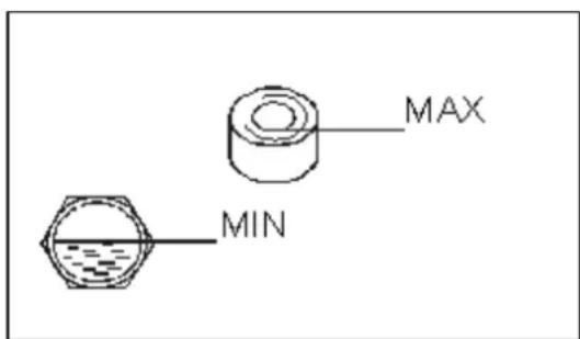
Abbildung 6
<= 15 KW

= 22 KW
Abbildung 7
EC-Declaration of Conformity
Fabricant: 63679 – Schotten, Germany
We hereby declare that the design and construction of the following described machines in their original factory configuration are in full conformity with the following list of EU guidelines, harmonized standards as well as other relevant technical standards:
Applied directives: 2004/108/EC, 2006/42/EC, 2006/95/EC, 2011/65/EC
Applied harmonized standards: EN 1012-1:1996, EN 60204-1:2006, EN 61000-6-2:2005, EN 61000-6-4-2007
Any unauthorised modifications to the machine nullify the validity of this declaration.
Description of machine: Compressor
Authorized person to compile the technical documentation :
63679 – Schotten, Germany
Schotten, Germany
Ort / Place / Lieu
Datum / Date / Date
Unterschrift / Signature / Signature CE-Officer
PREBENA
Description of machine: Compressor
Type of tool: SK-7,5-10
Type d'appareil:
TECHNISCHE DATEN
Füllleistung
1000 l/min
Supply voltage (input)
-400V\~
Line frequency
-50Hz
Electric protection, delayed-action
-15.6A
Power input
-7500W
Max. operating speed
- 5900 rpm
Vessel Capacity
-2701
Oil quantity'
-4.81
Dimensions L x W x H
- 1300 x 680 x 1585 mm
Weight
- 345 kg
Compression final pressure
- 10 bar
Noise characteristics
- LpA = 72 dB (A)
Implementation temperature
- + 5irc C to +40irc C
Min. distance to wall
- 50cm
1 Lubricant recommended
PREBENA Special- Synthetic -Oil
Order no.: Z200.80
DONNÉES TECHNIQUES
Dimensions L x L x H
- 1300 x 680 x 1585 mm
Poids
- 345 kg
Pression finale de compression
- 10 bar
Type of tool: SK-15-10
Type d'appareil:
TECHNISCHE DATEN
Füllleistung
- 1900 l/min
Supply voltage (input)
-400V\~
Line frequency
- 50 Hz
Electric protection, delayed-action
-29.3A
Power input
- 15000 W
Max. operating speed
- 6060 rpm
Vessel Capacity
-5001
Oil quantity 1
-5.51
Dimensions L x W x H
- 2015 x 680 x 1585 mm
Weight
- 490 kg
Compression final pressure
- 10 bar
Noise characteristics
- LpA = 77 dB (A)
Implementation temperature
-+5°C to +40°C
Min. distance to wall
- 50cm
1 Lubricant recommended
PREBENA Special- Synthetic -Oil
Order no.: Z200.80
DONNÉES TECHNIQUES
Dimensions L x L x H
- 2015 x 680 x 1585 mm
Poids
- 490 kg
Pression finale de compression
- 10 bar
Notizen – notes - notes:
Notizen – notes - notes:
Contents
1 General information .... 3
2 Scope 3
3 Safety information.... 3
4 Purpose 6
5 Specifications 6
6 Commissioning 6
7 Functions and operation 10
8 Maintenance 19
9 Troubleshooting and fault correction.... 29
10 Transport, storage and disposal 31
11 Guarantee 32
Appendix
A Declaration of conformity ....
B Tables ....
C General structure ....
D Exploded drawings / spare parts lists ....
E Schematic circuit diagrams ....
F Maintenance ....
1 General information
1.1 These operating instructions and the technical data sheet contain the technical specifications for the compressor as provided by the manufacturer, the precise operating instructions and maintenance instructions.
1.2 Before using the compressor, the operator must carefully read and follow the instructions in this manual to ensure safety and the proper operation of the compressor.
1.3 For additional components, consult the following manuals:
• ELECTRIC MOTOR
- AIR DRYER
• OIL / WATER SEPARATOR
- FILTER SYSTEMS
• AUTOMATIC CONDENSATE DRAIN
1.4 The manufacturer reserves the right to make changes in relation to the construction and design of the compressor in order to improve the performance and life of the compressor, without notice and without mentioning it specifically in this manual.

NOTE: THIS COMPRESSOR IS EQUIPPED WITH AN ELECTRONIC CONTROL, WHICH MONITORS IT AND SENDS MESSAGES REGARDING ITS OPERATION, MAINTENANCE AND ALARM STATUS.
2 Scope of delivery
The full scope of delivery for the compressor is provided in Appendix B.
2 Safety information
2.1 The safety information on the compressor must be kept in a legible condition.
2.2 The security requirements meet the EN1012 and IEC 60204-1 standards.
2.3 The notes have the following meanings:
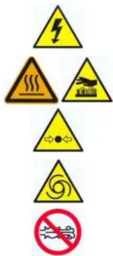
DANGER
High voltage
DANGER
High temperature
DANGER
Vacuum
DANGER
This unit operates automatically and without warning
Only open the valve only after connecting the pneumatic hose
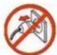



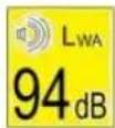
Do not remove the plug during operation
The operator must read the instructions
Ensure that all moving parts, protective equipment and covers are securely held in place
Start / Stop button
Noise characteristic value
2.4 Pay particular attention to all Notes with the following warning symbol.

2.5 Maintenance and operation of the compressor may only be performed by persons who are familiar with the construction and operation regulations and the safety and first aid instructions.
2.6 The compressor is used for the compression of atmospheric air. It must not be used to compress other types of gas.
2.7 Compressed air can be used for various purposes such as: Motor charging, pneumatic tools, dyeing, cleaning with water based agents, etc. It is important that, in all cases, the operating procedure and the applicable regulations are known and are adhered to.
2.8 During operation, make sure that the compressor is in perfect condition and all malfunctions are corrected immediately.
2.9 Adhere to current standards and fire regulations during operation.
2.10 Always wear protective goggles when operating the compressor to protect your eyes from foreign objects that may be present in the air stream.
2.11 If there is excessive noise, appropriate hearing protection must be worn.
2.12 Do not use compressor parts as a support or guide.
2.13 Safety regulations for the operation of the pressure vessel:
- Operate the pressure vessel correctly and within the pressure and temperature limits;
- Always pay attention to the condition of the protective devices and control units. Check that the pressure switch and safety valve, other valves and pressure gauge are working properly;
- Release the resulting condensate from the pressure vessel once daily.
• OPERATE THE COMPRESSOR WITH WET HANDS OR WITH WET SHOES;
- POINT THE COMPRESSED AIR FLOW TOWARDS A PART OF YOUR BODY OR ANOTHER PERSON IN THE AREA;
- GRANT UNAUTHORISED PERSONS, CHILDREN OR ANIMALS ACCESS TO THE WORK AREA;
- STORE KEROSENE, PETROLEUM OR OTHER FLAMMABLE LIQUIDS IN THE COMPRESSOR LOCATION;
- LEAVE THE COMPRESSOR CONNECTED TO THE POWER SUPPLY, WHEN NOT IN USE;
- CARRY OUT REPAIRS TO THE COMPRESSOR IF:
- IT IS CONNECTED TO THE POWER;
- IT IS PRESSURISED;
- NO MEASURES HAVE BEEN TAKEN TO PREVENT IT FROM BEING INADVERTENTLY TURNED ON: MOTOR START, COMPRESSED AIR SUPPLY;
• TRANSPORT THE COMPRESSOR UNDER PRESSURE.
4 Purpose
4.1 The compressor is used to generate compressed air for the supply of pneumatic equipment, devices and tools in industry and in the craft sector. Depending on the type, the compressor may not be equipped with a filter to remove moisture or aerosol (spray), liquid and vaporised oil particles. In order to produce particularly pure compressed air, the installation of an appropriate filter / dryer is required.
4.2 The compressed air produced by the unit may not be used for pharmaceutical, food processing or sanitary purposes without subsequent special filtering.
4.3 The compressors are designed for continuous operation.
5 Specifications
5.1 The compressor has been designed and manufactured in accordance with the general safety requirements and standards relating to this type of device and in accordance with applicable technical regulations.
5.2 The main technical specifications for the compressor are provided in Appendix B.
5.3 For the technical specifications of the drive belt for the compressor, please refer to Appendix B.
5.4 For the technical specifications of the electric motors, please refer to Appendix B.

NOTE: THE BUILT-IN ELECTRIC MOTOR HAS AN EFFICIENCY RATING OF IE2 FOR INSTALLATION IN A COMPRESSOR.
5.5 For the technical specifications of the screw unit, please refer to Appendix B.
5.6 The compressor must be connected to a three phase power source (400V). The voltage and nominal values for the power supply and the current frequency are provided in Appendix B of this user manual.
5.7 The pressure within the air / pressure vessel is automatically controlled by the electronic control unit and the compressor control unit.
5.8 The compressors operate reliably at ambient temperatures from +5 °C to +40 °C, and at a maximum relative humidity of no more than 90%.
6 Commissioning
6.1 General information
Unpack the compressor carefully and check that the delivery is complete. Make sure that there are no visible signs of shipping damage.
- Remove the housing panels of the compressor.
- Perform a visual inspection for oil or other leaks.
- Check the oil level through the inspection window of the oil indicator.
It is recommended that the oil be refilled or replaced as described in Point 8.3.3 of this manual. Spare parts (oil filter, air filter, oil separator and a series of belts) required for technical maintenance must be obtained from the dealer or manufacturer.
6.2 Commissioning of the pressure vessel
The operation and manufacturing processes of the pressure vessel are governed by local laws.
The documents for the pressure vessel and the associated compressor must be safely stored throughout the life of the pressure vessel.
6.3 Installation

DO NOT OPERATE THE COMPRESSOR IN LOCATIONS WITH RISK OF EXPLOSION OR FIRE!

DO NOT OPERATE THE COMPRESSOR IN RAIN!
6.3.1 The overall dimensions of the compressor are stated in Appendix B.
6.3.2 In order that the compressor functions normally, the ambient temperature should not be lower than +5 °C, and no higher than +40 °C. Operation at a lower temperature leads to the penetration of condensate into the oil, thereby reducing its lubricating properties, which results in the reduced service life of the screw unit and increases the probability of failure.
The operation of the system at temperatures above the maximum value leads to a reduced efficiency coefficient in the heat exchanger and the oil cooling system.
An increased oil temperature triggers the activation of the thermal protection system, which stops / prevents the operation of the compressor. The operating temperature is displayed in the LED display of the control unit. The suctioned air must not contain dust nor explosive or flammable gases, solvents or colouring agents in aerosol form or toxic fumes.
6.3.3 Mounting of the rubber shock absorbers (compressors without boiler only)
Removable rubber shock absorbers must be mounted on the supports of the screw compressor housing.

DO NOT PERMANENTLY MOUNT THE COMPRESSOR TO THE FLOOR OR THE BASE PLATE!
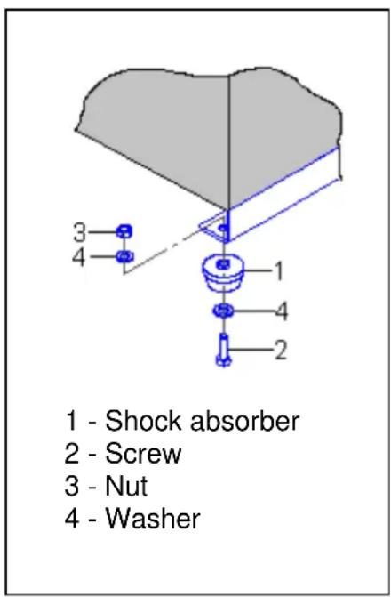
Figure 1
6.3.4 Place the compressor on a horizontal flat surface in order to ensure better lubrication of the moving parts and the complete drainage of the condensate. Make sure that the compressor is installed on a flat, non-slip surface made of oil, fire and wear-resistant material.
6.3.5 Ensure easy access to control unit, suction filter and condensate drain regulator. To ensure proper ventilation and effective cooling, the compressor must be at least 50 cm from the wall.
6.4 Connection to an air system
6.4.1 When connecting the compressor to an air system or an execution unit, you must use pneumatic valves and flexible hoses with the correct dimensions and properties (diameter, pressure and temperature).
6.4.2 It is recommended that the outlet be equipped with a pressure reducing valve or similar fitting in order to ensure the reduction of the pressure of the discharged air from the pressure vessel.
6.5 Connection for secondary use of the emitted thermal energy
The heat emitted by the compressor cooler can be re-used. The discharged air contains heat and can be used at the compressor site or in another building area as air heating. If the latter is being considered, then the collection hood / duct component for transporting the expelled air must have a greater cross sectional area than the radiator. It is also necessary to further convey the air using a mechanical ventilator, to ensure a constant flow rate of air.
The collection hood / duct component directly above the radiator must be removable for inspection purposes.
6.6 Connection to the power supply
The permissible voltage fluctuations in the power supply should correspond to the data specified in the included manual.
Electrical cables must meet all safety standards and must have a cross-section that is in keeping with the power consumption of the compressor. All electrical connections must be realised by a qualified electrician. The compressor must be connected to the power supply by means of a fixed connection with appropriate insulation.
The compressor is equipped with an on/off switch for maintenance and repairs. The compressor must be properly earthed. Connect the protective conductor of the power cable to the PE connection (switch cabinet) in accordance with IEC 60204-1 requirements.
The earthing wire must have a solid core copper with a cross section as shown in Appendix B.
In accordance with IEC 60204-1, the power supply must have a circuit breaker.
The power supply to the compressor must be equipped with a circuit breaker (fuse) to protect the compressor against short circuits. This must be designed to comply with the emergency circuit breaker.
The compressors are suitable for use with a three phase power supply (400 V, 50 Hz), with a tolerance of 10% or 1%. The electric motor has a star-delta circuit. The voltage across the entire control and signalling circuit is 24 volts AC.
6.7 Schematic circuit diagrams for the compressors can be found in Appendix E.
7 Functions and operation
7.1 Functions
7.2 Functional principle
The air from the atmosphere passes through the air filter and the intake valve to the pair of screws, where it is mixed with oil and compressed. The air-oil mixture is transported under pressure to the oil sump, where the first coarse filtration / separation takes place. Due to its high self-weight, the oil runs down to the bottom of the oil sump housing.
Subsequently, the air-oil mixture enters the filter / separator, where the final filtration / separation of the oil and air mixture takes place.
The oil will be transported via the oil line / oil hose into the radiator where it cools and is filtered through the oil filter and again reaches the pair of screws, so that the cycle can start again. The oil has the task of cooling the air during the compression cycle, of lubricating the bearings and sealing the surface of the screw.
The air, which is cleaned of the oil residues by the filter / separator, is cooled as it flows through the air circuit of the cooler. Then, at a substantially lower temperature and with just minor water and oil residues, it reaches the outlet.
7.3 The functional diagram of the compressor unit can be found in Appendix C.
7.3 The general structure of the compressor can be found in Appendix C.
7.5 The control unit is constructed as shown in Figure 2: The operating instructions for the electronic control unit can be found in Point 7.8.
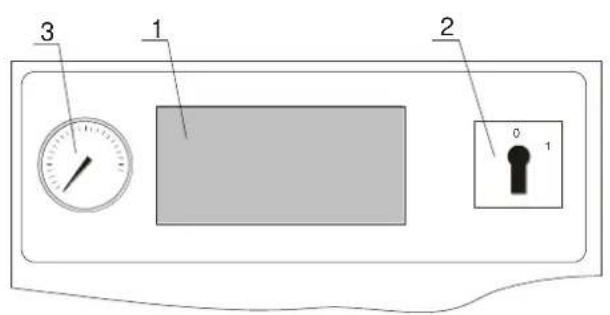
1- Electronic control unit
2- Main switch
3- Manometer
Figure 2
7.6 Compressor unit protection devices
The compressor is equipped with the following safety devices and control units that contribute to the protection and control of the main components and functions. These are as follows:
1 Safety valve, which is mounted to the compressed air tank (if present).
2 Safety valve, which is mounted to the oil collection tank.
3 Fuses FU 1-FU5 (5.5, 7.5, 22, 30 and 37 - KW) FU 1-FU8 (11 and 15 KW) (SeeAppendix E): for the protection of all control and signal circuits.
4 Circuit breakers, which provides protection against short circuits in the power supply.
5 Power monitoring, which provides protection against losses and asymmetric phases, as well as false phase sequences.
6 Temperature relay (on the wiring board) to protect the compressor motor against overload. The compressor is switched off when the temperature relay is switched.
7 Programmable controller, which monitors temperature and pressure and regulates the compressor automatically.
8 In the following cases, switching the compressor normally is not possible and the electric circuit is separated:
- Voltage recovery after power failure;
- Increase in oil temperature to above the permissible limit of +100 °C
- Use of the temperature relay;
- Indication of excess pressure.

DANGER: THE COMPRESSOR WAS STOPPED IN THE CASE OF AN EMERGENCY (ACTIVATION OF PROTECTION SYSTEM). FIND THE REASON FOR THE FAILURE BEFORE RESETTING THE COMPRESSOR AND CHECK THE THE FOLLOWING POINTS:
1 VOLTAGE, CHANGE IN THE THREE PHASES OF THE POWER SUPPLY. CHECK PHASE VOLTAGE AND CONNECTIONS.
2 IN THE CASE OF ACTIVATED MOTOR THERMAL PROTECTION:
- ALLOW THE THERMAL PROTECTION TO AUTOMATICALLY RESET.
- PRESS THE "RESET" BUTTON.
- SWITCH THE COMPRESSOR ON.
3 IN THE CASE OF ACTIVATED COMPRESSOR THERMAL PROTECTION, CHECK:
- IF OIL LEVEL AND SPECIFICATIONS ARE CORRECT.
- IF THE FAN / RADIATOR IS CLEAN.
- THE AMBIENT TEMPERATURE.
- THE FILTER LOAD.
- IF THE TEMPERATURE DROPS TO 97°C, PRESS THE "RESET" BUTTON AND SWITCH THE COMPRESSOR ON.
If all of the above mentioned measures have been completed and the compressor still does not work, or the deactivation error persists, then contact the company that carries out the annual maintenance of the compressor, or contact the seller or manufacturer.
A check regarding the direction of rotation of the drive shaft of the screw unit (indicated by an arrow on the screw unit housing) is performed by a technician during the installation and commissioning of the compressor. The voltage control relay shuts off the compressor to prevent it from being switched on in spite of the incorrect phase connection or an unacceptable operating voltage in the power supply.
7.7 Operation
7.8 AirMaster P1 Controller
7.8.1 Specifications
The multifunctional electronic control unit (AirMaster P1 controller) has been developed in accordance with EU directives and standards. The controller is designed for the control of the screw compressors. The corrosion-resistant housing of the controller is made from aluminium alloy.
The controller has a polyethylene keyboard rated as compliant with protection class IP65 and IP20 (other elements).
The communication of the input and output signals is realised by the contact switch. The X01 controller is powered from the mains - 24VAC is +/- 15%, frequency 50 or 60 Hz. Max. power consumption of the controller is 220mA. All information is displayed using a 45mm x 25mm Liquid Crystal Display (LCD) (illuminated).

THE EMERGENCY STOP SWITCH CAN ONLY BE PRESSED IN AN EMERGENCY!

DANGER: IN THE EVENT OF THE FAILURE OF A PHASE (40s OR MORE) AND IN CASES OF UNDERVOLTAGE (UNDER 19.8 VAC) THE CONTROLLER SWITCHES THE COMPRESSOR OFF!
7.8.2 Controller display
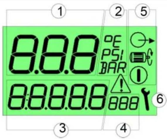

Started
Measurement units

- Operating Basic operating menu values

Under load Operating menu measurement units

Modaintenance

- Warning
1: Basic display values
(bar, psi,
(0,1......999)
(bar, psi,
6: Maintenance symbols
(0,1.....999)
irc C, irc F)
irc C, irc F, Hr, Lhr)
Figure 3
The controller has a long-term memory for the storage of operating data: Operating time, hour meter reading, system modes, etc.
Input: X02 analogue input (contacts 1 and 2):
Pressure transducer, (contacts 3 and 4): Temperature sensor; X03 digital input - two-digit 224 VAC digital input for inspections: Emergency stop alarm, motor protection alarm (drive),
Motor protection alarm (fan), phase control.
Output: X04 Digital output - four-pole output by means of relay (up to 2A reactive load 230VAC), resources for 100,000 control cycles: Main protection switch, star protection switch, delta protection switch, electromagnetic valve.
7.8.3 Controller keys
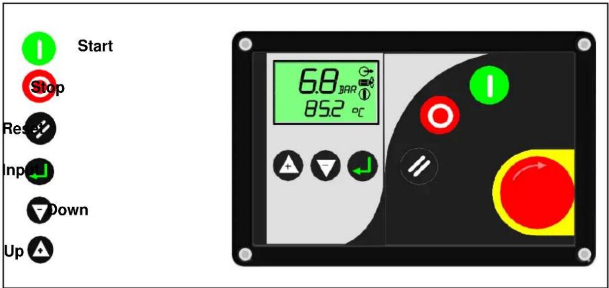
Figure 4
7.8.4 Functional Description
When switching on the compressor, the pressure at the air output and the temperature of the air-oil mixture (at the screw pair) are shown on the display. There are three operating modes, which are indicated with the following symbols:

Standby mode (the motor is switched on and when the required pressure value is reached, the system starts automatically).
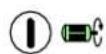
Idle mode (control valve is off, the motor is running). The time left before the transition into standby mode or operating mode is shown (Launch Countdown).
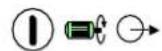
Operating mode (the motor is running, the control valve is switched on).
To select the desired parameter, use the (up) and (down) keys.




Basic values of the display (bar or psi)


Temperature ( irc C or irc F)


23456Hr Total run rime of the system, in hours
16420LHr The run time of the system in operating mode, in hours
2000H1 Air filter hours
4000H2 Oil filter hours
4000H3 Oil separator filter hours
4000H4 Oil change hours
500H5 Service hours
7.8.5 Indications on the display
"A" Warning: Symbol lights up, the compressor continues to run.
| Code | Message |
| A: 2050 | Settings error for digital input C5 (not relevant) |
| A: 2060 | Settings error for digital input C6 (not relevant) |
| A: 2118 | Overpressure (maximum pressure value + 0.2 bar). |
| A: 2128 | Overtemperature of the air-oil mixture (about 97°C) |
| A: 2816 | Power failure |
| A: 3123 | Temperature is below the low temperature set point |
| A: 3423 | Undertemperature - operation is not possible. Manually deletion of the error, (Reset) it is not possible |
| A: 4804 | The time to replace the air filter has expired |
| A: 4814 | The working time of the filter has expired |
| A: 4824 | The time to replace the oil separator has expired |
| A: 4834 | The time to replace the oil has expired |
| A: 4844 | The time to perform other maintenance has expired |
"E" Warning: The
symbol flashes, the compressor is stopped.
| Code | Error | Solution |
| E: 0010 | EMERGENCY STOP | The EMERGENCY STOP button was pressed. Reset the switch to the correct position |
| E: 0020 | Overloading of the motor (compressor) | Check: the function of the electric motor, the settings for the heat relay, the belt tension, the air temperature in the control cabinet |
| E: 0030 | Overloading of the motor (fan) | Check: the function of the electric motor, possible mechanical faults |
| E: 0040 | Phase defect or incorrect phase sequence | Check whether phase is available |
| E: 0050 | (not assigned) | |
| E: 0060 | (not assigned) | |
| E: 0115 | Pressure sensor defective or damaged | Check the sensor connection, and replace if necessary |
| E: 0119 | Extreme pressure alarm (extreme pressure value + 0.3 bar) | Check the compressor functionality |
| E: 0125 | Temperature sensor defective or damaged | Check the connection of the sensor, measure the resistance, if necessary replaced sensor |
| E: 0129 | The excess temperature of the air-oil mixtu (over 100 °C) | Check: The oil level, filter, function of the thermostat, radiator for dirt |
7.8.6 Service Countdown Timers
There are 5 Countdown Timers:
- Air filter hours
- Oil filter hours
- Oil separator hours
- Oil change hours
- Service hours
7.8.7 Menu access
To get access for the individual menu items, please contact your Service Provider or the manufacturer.
Operation menu
| Item | Code | Description | Range | Setting |
| 1 | 1.PU | Upper pressuresetting | 1 to 68 bar | 10.0 bar |
| 2 | 1.PL | Lower pressure setting | 0.8 to 67.8 bar | 7.8 bar |
| 3 | 1.P- | Pressure Display Units | bar / psi | Bar |
| 4 | 1.t- | Temperature Display Units | ircC , ircF | ircC |
| 5 | 1.bt | Blowing time | 0 to 12 0 seconds | 30 seconds |
| 6 | 1 .Hr | Stop time | 0 to 30 seconds | 10 seconds |
| 7 | 1.p | Pressure display Units | bar /psi | Bar |
| 8 | 1.t- | Temperature Display units | ircC / ircF | ircC |
| 9 | 1.At | Auto restart time | 0 to 120 seconds | 10 seconds |
Configuration menu
| Item | Code | Description | Range | Setting |
| 1 | 2.sd | Motor star-delta time | 0.0 to 20.0 Seconds | 5.0 seconds |
| 2 | 2.Ad | Network address (RS485 option) (not assigned) | 1 to 12 | 1 |
| 3 | 2.LS | Download source (not assigned) | 0=local, 1=RS485, 2=Dig.In. | 0=local |
| 4 | 2.SS | Start source (not assigned) | 0=local, 1=RS485, 2=Dig.In. | 0=local |
| 6 | 2.PF | High pressure level | 0.8 to 67.8bar | 10.5 bar |
| 7 | 2.TA | High temperature alarm level | 50 to 248°C | 110°C |
| 8 | 2.tF | High temperature level | 52 to 250°C | 110°C |
| 9 | 2.d2 | Digital input "C2" (not assigned) | ---- | ---- |
| 10 | 2.d3 | Digital input "C3" (not assigned) | ---- | ---- |
| 11 | 2.d4 | Digital input „C4“ (not assigned) | ---- | ---- |
| 12 | 2.d5 | Digital input „C5“ (not assigned) | ---- | ---- |
| 13 | 2.d6 | Digital input "C6" (not assigned) | ---- | ---- |
| 14 | 2.Po | Pressure sensor "offset" calibration | -1.5 to 1.5 bar | 0.0 bar |
| 15 | 2.Pr | Pressure sensor "range" calibration | 0.0 to 105 bar | 16.0 bar |
| 16 | 2.tL | Prevent low temperature stress | 1 to 70°C | 2.0°C |
| 17 | 2.tr | Prevent low temperature run | -20°C to 10°C | -10°C |
| 18 | 2.L1 | Operation menu access code | 0 to 9000 | 000* |
| 19 | 2.L2 | Configuration menu access code | 0 to 9000 | 0*** |
| 20 | 2.Af (H1) | Air filter hours | -999 To 3000 Hrs | 2000 Hrs |
| 21 | 2.Of (H2) | Oil filters hours | -999 to 3000 Hrs | 4000 Hrs |
| 22 | 2.Se (H3) | Oil separator filter hours | -999 to 3000 Hrs | 4000 Hrs |
| 23 | 2.Oc (H4) | Oil change hours | -999 to 3000 Hrs | 4000 Hrs |
| 24 | 2.Sh (H5) | Service hours | -999 to 3000 Hrs | 500 Hrs |
| 25 | 2.rt | Line overflow time | 0 to 600 seconds | 300 seconds |
| 26 | 2.bt | Blowing time | 0 to 120 seconds | 30 seconds |
| 27 | 2.St | Stop time | 0 to 30 seconds | 10 seconds |
| 28 | 2.At | Auto restart time | 0 to 120 seconds | 10 seconds |
7.8 Initial commissioning
Turn the main switch to position "I". The air pressure and screw temperature are displayed on the control unit. Press the START button to switch on the compressor. If the compressor does not start up upon pressing the START button, perform troubleshooting and follow the instructions in the appropriate section of the manual. When the compressor starts, fully open the bleed air valve fully and keep the compressor disconnected from any distribution systems. Then let the compressor run for several minutes without load to ensure the proper oil flow and lubrication of the worm screw.
DANGER: BEFORE INITIAL COMMISSIONING:
- FAMILIARISE YOURSELF WITH THE SYSTEMS AND COMPONENTS OF THE COMPRESSOR.
- VERIFY THAT THE SCREW TURNS IN THE DIRECTION INDICATED ON THE HOUSING AND THAT THE AIR FLOW IS DIRECTED UPWARD. IF THE SCREW ROTATES IN THE WRONG DIRECTION, THEN CHANGE THE PHASE CONNECTION OF THE POWER CORD.
- MAKE SURE THAT THE SYSTEM IS PROPERLY VENTILATED
- MAKE SURE THAT ALL COMPONENTS ARE PROPERLY SECURED.

7.9 Switching on the compressor
Start the compressor with an electric motor connected to the mains as follows:
1 If the connection is made via a local switch, switch it on.
2 Turn the main switch to position "I".
3 Press the START button to switch on the compressor
7.10 Switching off the compressor
To switch off the compressor when it is not in use, perform the following steps:
- Press the "STOP" button.
- Once the compressor stops, switch off the electric motor by turning the main switch to "0".
- The compressor cannot be restarted for 2 minutes following the manual switch off.

DANGER: ONLY USE THE "EMERGENCY OFF" SWITCH IN EXTREME CASES.
7.12 Monitoring and control processes in the operating sequence
When the predetermined maximum pressure is reached, the controller outputs a control signal to open the safety valve and the compressor will automatically switch to idle state. The intake valve then closes and the load is removed from the compressor.
When the pressure has been reduced to the predetermined minimum, the controller outputs a control signal to close the safety valve and open the intake valve. The compressor switches to operating mode and the pressure increases.
In automatic mode, the compressor switches off at regular intervals, if idle mode is activated during normal operation. This happens when the user switches off the air supply. This state is called "Standby" mode. "STANDBY" mode is only activated when the user switches off the air consumption or the compressor and this remains idle for more than 5 minutes. The compressor remains in this mode until the pressure falls below the lower limit of 2 bar. The compressor then automatically switches on again.

DANGER: BY PRESSING THE "STOP" BUTTON, THE COMPRESSOR SWITCHES TO "IDLE" MODE AND WILL THEN AUTOMATICALLY BE SWITCHED OFF AFTER A SPECIFIED TIME (DEPENDING ON MODEL, 30 TO 50 SECONDS).
To restart the compressor, press the "START" button.
8 Maintenance
8.1 During technical inspections, observe the instructions in this manual and the applicable health and safety rules and regulations.

DANGER: BEFORE PERFORMING ANY TYPE OF SERVICE, ENSURE THAT THE COMPRESSOR IS DISCONNECTED FROM THE POWER. THE AIR SYSTEM MUST BE SWITCHED OFF AND MUST NOT BE PRESSURISED

DANGER: SOME EQUIPMENT SURFACES CAN BECOME VERY HOT!

NOTE: PERFORM THE GENERAL CHECKS AFTER THE FIRST 50 OPERATING HOURS: CHECK THE OIL LEVEL, THE CONDITION OF THE RADIATOR, THE AIR FILTER, THE BELT TENSION AND THE GENERAL CONDITION OF THE ELECTRICAL CONNECTIONS AND ELECTRICAL EQUIPMENT.

NOTE: PERFORM THE FIRST OIL AND OIL FILTER CHANGE AFTER 500 HOURS (BREAKING-IN TIME) OR ONE YEAR AFTER DATE OF PURCHASE, DEPENDING ON WHICH OCCURS FIRST.
8.2 Ordering of spare parts
When ordering spare parts, the following information must be available to ensure you receive the right part:
- Model number
- Serial number
• Max. operating pressure - Compressor power
• Description of the part or part number / code, if available
• Description of all modifications and appropriate modification number
8.3 Maintenance instructions
To ensure the continuous and safe operation of the compressor, follow the maintenance instructions as specified below in Table 1.
Table 1
| Action to be performed | Maintenance schedule | |||||
| Daily (WD) | 500 Hours (W) | 2,000 hours (Min. twice per year) | 4,000 hours (Min. once per year) | 8,000 hours (Min. once every two years) | 20,000 hours (Min. every six years) | |
| 1. Visual inspection of the compressor for mechanical damage, strange noises and knocking noises, oil leaks. If present, rectify any errors. (8.3.14)2. Oil level check. If necessary, refill. (8.3.1)3. Check the measured values and the operation of devices and equipment.4. Check pneumatic connections for tightness and tighten if necessary. (8.3.13)5. Check the oil in the inspection window of the oil separator. (8.3.1) | + | + | + | + | + | + |
| 1. Check the radiator. If necessary, clean with compressed air.2. Check the purity of the oil (intense dark colour) and change oil if necessary. (8.3.1)3. Check the connectors of electrical devices or power cables. (8.3.14) | - | + | + | + | + | + |
| 1. Replacement of the air filter; (8.3.9)2. Belt tension check. If necessary, adjust. (8.3.7) | - | + | + | + | + | + |
| 1. Oil change.* (8.3.3)2. Replacement of the oil filter.* (8.3.10)3. Replacement of the filter-oil separator (separator). (8.3.11)4. Safety valve check. Replace if necessary. (8.3.15)5. Checking of the pressure vessel condition. | - | - | - | + | + | + |
| 1. Replacement of seals.2. Replacement of the seal set at the suction valve.3. Replacement of the seal set at the minimum pressure valve.4. Replacement of the seal set at the thermostat.5. Replacement the seal set at the screw conveyor unit. | - | - | - | - | + | - |
| 1. Replacement of the complete set of belts on the screw conveyor unit. (8.3.6)2. Replacement of the bearings at the electric motor. | - | - | - | - | - | + |
| NOTE:1 For the tasks specified in the schedule that are planned for longer time intervals, the work to be performed at the shorter intervals is included.2 * Perform the first oil change and oil filter replacement after 500 operating hours and the next after 4000 operating hours, but at least once per year. | ||||||
8.3.1 Checking the oil level
The oil level is visually (Figure 6) inspected. The maximum fill level is the lower edge of the oil filler neck and the lower limit is located at the centre of the viewing window (in the case of a cold compressor). If oil colour changes occur (whitening- contains water, darkening - extreme overheating), change the oil immediately (point 8.3.3).
8.3.2 Recommended types of oil
The nominal lubricating oil capacity for the compressor can be found in the "Spare parts for maintenance" table in Appendix F. It is recommended that your do not mix the different varieties and mineral compositions of the oil. We advise using the following oil brands and types for the compressor. However, similar or equivalent oil brands or types can be used. The screw compressor is shipped from the factory with mineral oil.
Manufacturer Type of oil
PREBENA Z.200.70 Mineralöl
PREBENA Z.200.80 Synthetiköl

WARNING: COMBINING DIFFERENT TYPES OF OIL AND OIL FROM DIFFERENT MANUFACTURERS IS STRICTLY FORBIDDEN AND VOIDS THE WARRANTY / GUARANTEE.

NOTE: SELECT A HIGH QUALITY OIL FOR SCREW COMPRESSORS, WITH A VISCOSITY OF 46 MM2/S AT 40°C, FLOW POINT FROM -8 to 10°C, WITH AN IGNITION TEMPERATURE OF MORE THAN 200 °C.
When replacing the compressor oil, it is important to completely remove the oil from oil reservoirs, screw conveyor unit, condenser and oil circulation lines. In addition, the oil filter and oil separator must be replaced.
8.3.3 Oil Change
When changing the oil, it is necessary:
1 To remove the right cover of the compressor housing.
2 To switch the compressor on, so that the oil can heat to over 71irc C (the radiator is simultaneously heated over the entire surface).
3 To switch off the compressor.
4 Within 5 minutes, unscrew the plug and slowly open the drain valve to remove the oil. Then all of the oil can be drained into a container and prepared for disposal.
5 To manually turn the screw 3-5 revolutions in the direction of the arrow on the front of the worm screw.
6 To remove the oil filter.
7 To install a new filter (before installing the filter, pour in a little oil so that the filter element is impregnated and then lubricate the gasket of the filter with oil). To do so, use the same oil as for filling the compressor.
8 To dismantle the filter / oil separator.
To install a new filter / oil separator, having previously greased the gasket of the filter with oil. To do so, use the same oil as for filling the compressor.
9 To close the drain valve and fill the new oil through the filler neck to the upper edge of the inspection hole of the oil indicator. Then screw the plug back into the filler neck.
10 To switch on the compressor and then switch it off again after reaching the oil temperature of more than 71irc C. After the oil-foam subsides, you can then check the oil level through the inspection window and top up if necessary.
11 To replace the right panel of the compressor housing.

NOTE: IN THE CASE OF AN ELEVATED DUST CONTENT IN THE AIR, MORE FREQUENT MAINTENANCE MUST BE PERFORMED. SPECIAL CONSIDERATION MUST BE GIVEN TO HE RADIATOR IN THIS REGARD. IT MUST BE CLEANED/REPLACED MORE OFTEN, ALONG WITH THE AIR FILTER.
8.3.4 Cap for draining oil
The cap for draining the oil is located at the bottom of the oil sump and serves the purpose of draining the oil during maintenance and oil change.
When draining the oil, the condensate must also be removed via the cap (if required).
All tasks / activities in which the cap has to be removed should be performed when there is no pressure in the oil sump and when the compressor is off.
8.3.5 Oil filler neck
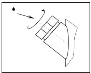
The oil filler neck is located directly on the oil tank and is locked with a special screw (Figure 5). This lock can only be opened when the pressure in the compressor corresponds to the normal air pressure. Danger: The cap should not be removed when the compressor is running or is pressurised.
natural_image
Simple line drawing of a mechanical component with motion arrows indicating direction (no text or symbols)Figure 5
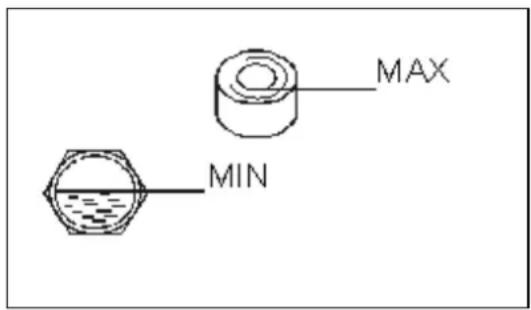
Figure 6
8.3.6 Replacement of the belt
When replacing the belt, the following is required:
a) Remove the right cover of the compressor housing and the protective device.
b) Loosen the four screws of the motor platform.
c) Reduce the belt tension by moving the motor platform in the direction of screw conveyor unit
d) Remove the belt.
e) Clean the grooves of the pulley with a cleaning cloth and install the new belt.
f) Now increase the tension by moving the electric motor platform away from the worm screw. Ensure that the belt tension and deflection are adjusted as shown in Figure 7.
g) Tighten the motor platform by tightening the screws firmly.
h) Place the protection device and the cover back on the compressor housing.
8.3.7 Checking the belt tension
The belt tension adjustment is performed in accordance with Point 8.3.6.
The power of the electric motor is transmitted by means of the contact of the belt with the pulleys. To ensure normal operation, all contact surfaces must be clean and the belt must be fully taught and set to the correct tension / deflection.
The belt tension should be checked after assembly and periodically during operation, especially if the compressor has not been used over a period of at least one week.
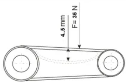
The belt deflection should be adapted and adjusted using a dynamometer, a string and a ruler (Figure 7).
The power is transmitted via the belt, whereby frictional forces are generated between the belt and pulleys, transferred from the electric motor to the drive of the screw assembly. To ensure normal operation, all surfaces of belts and pulleys must be kept clean and tightened to the correct pressure.
The belt tension must be checked after assembly and periodically during operation, especially if the compressor has not been used over a period of at least one week.
3 to 5 operating hours after the belt change, check the tension, since the belt has been subject to intensive expansion during this period, which may lead to a friction-induced slippage and thus to power loss and damage.
For compressors up to 15 kW: The belt must be tightened and may only yield up to a maximum of 5-6 mm at an applied force (F) of 30 N (Figure 7).
For compressors from 22 KW: The belt must be tightened and may only yield up to a maximum of 4-5 mm at an applied force (F) of 35 N (Figure 7).
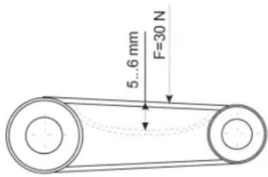
<= 15 KW
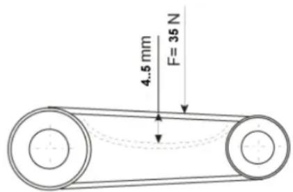
> = 22KW
Figure 7
8.3.8 Checking the intake filter (filter element)
The compressor requires a large volume of air for operation and internal ventilation / cooling. Therefore, an excessive amount of dust in the air leads to a malfunction in the normal operation of the compressor. A certain amount of dust remains in the air intake, meaning that it clogs quickly. The dust settles quickly on various internal modules and components, including the air / oil cooler, and hinders the heat exchange / cooling process. For this reason, it is important to check the air intake before operation and to clean the work area regularly. This is the only way that the normal operation of the system can be ensured and unexpectedly high maintenance costs avoided.

DANGER: IF THE AIR IS MIXED WITH ORGANIC AND MINERAL DUST OR CORROSIVE CHEMICAL VAPOUR, THE COMPRESSOR MUST BE IMMEDIATELY SUPPLIED WITH CLEAN / FILTERED AIR.
8.3.9 Replacement of suction filter (filter element)
This must be performed every 500 hours or at least three times per year. Proceed as follows:
- Open the cover to access the air filter.
- Loosen the wing nut and hold the cover of the housing secure.
- Remove the air filter element and install a new one.
- Replace the cover and tighten the wing nut.
8.3.10 Oil filter change
This must be performed every 4000 hours or at least once per year. Proceed as follows:
- Open the front door of the compressor.
- Turn the oil filter anti-clockwise to remove it.
- Carefully clean the seat of the oil filter housing.
- Pour some oil into the new filter until the filter element is saturated.
- Apply some oil to the new filter gasket.
- Turn the oil filter clockwise by hand. To do this, do not use any tools, because you may damage the housing of the oil filter.
8.3.11 Replacement of the oil separator
This must be performed every 4000 hours or at least once per year. Proceed as follows:
- Open the front door of the compressor.
- Turn the separator anti-clockwise to remove it.
- Carefully clean the seat of the separator housing.
- Apply some oil to the new separator gasket.
- Tighten the trap clockwise by hand, do no use any tools as you may damage the housing of the separator.
- Check the oil separation after 2 to 3 hours (display).
8.3.12 Condensate drainage
Drain the condensate daily and after each use.
1 Switch off the compressor in accordance with Point 7.11.
2 Decompress the pressure vessel to 2-3 bar.
3 Place a container beneath the condensate drainage point.
4 Open the ball valve and drain the condensate.
5 Close the ball valve.
6 Dispose of the drained condensate in accordance with environmental protection regulations.

DANGER: NEVER DRAIN CONDENSATE OR OIL FROM THE PRESSURE VESSEL WHEN PRESSURISED. BEFORE PERFORMING ANY MAINTENANCE, RELEASE PRESSURE AND SWITCH OFF THE SYSTEM.
8.3.13 Checking the connection tightness of the air line
Check the connection tightness of the air line daily and before each use. To check the connection tightness, the compressor should be switched on and the pressure in the pressure vessel should be a maximum of 5-7 bar. There must be no audible air leaks at the connection points. If necessary, tighten the connection points.

DANGER: BEFORE TIGHTENING THE CONNECTION POINTS, THE COMPRESSOR MUST BE DEPRESSURISED!
8.3.14 External inspection of the compressor
Check the electric cable, the safety valve, the pressure gauge, the pressure vessel and the pressure switch for damage that could compromise the correct operation daily and before each use. Ensure that there are no deformities or fractures and that the earth wire is connected properly.
8.3.15 Checking the safety valve on the compressed air container (applies only to models with a compressed air tank)
The safety valve is a valve spring (Figure 8). It has been adjusted in the factory, set to the correct opening pressure and sealed. Breaking the seal and changing the setting is prohibited and is not possible without destroying the integrity of the valve body. Interventions to the safety valve void the manufacturer's warranty.
A test of the safety valve can be performed during normal compressor operation. The safety valve can be tested as soon as the pressure in the compressed air container is ≥ 85% of the opening pressure.
The valve can be inspected manually via the pull ring on the upper part of the safety valve. The test proceeds as follows: Pull the ring up when the upper pressure level has been reached in the pressure vessel. Continue pulling until the valve is half open and discharges pressure, then let the ring go so that it can return to the home position again. If the valve can no longer seal the valve seat, it is broken and must be replaced.
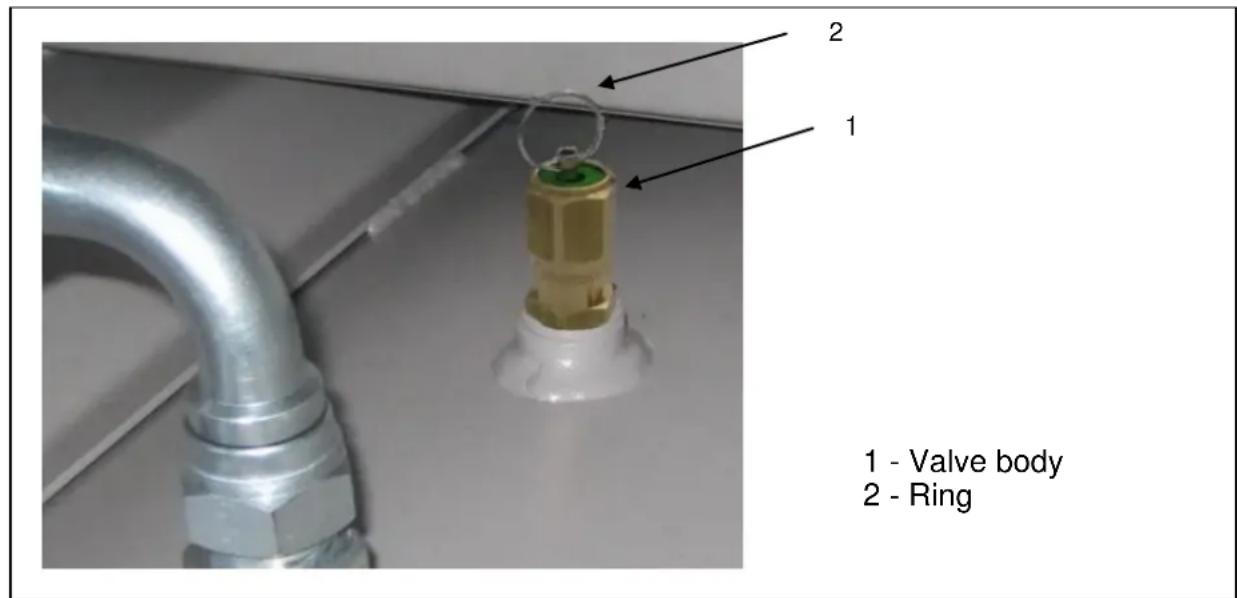
Figure 8

NOTE: IF THE PRESSURE VESSELS IS DELIVERED WITH A SAFETY VALVE WITHOUT A MANUAL TEST RING, THEN TEST BY REMOVING THE SAFETY VALVE (ENSURE THE PRESSURE IN THE PRESSURE VESSEL CORRESPONDS TO THE NORMAL AIR PRESSURE AND THAT THE COMPRESSOR IS SWITCHED OFF). THE FUNCTIONALITY IS THEN TESTED ON A TEST STAND, AT LEAST ANNUALLY.
8.4 Install the protection equipment and other components after maintenance is complete. Observe the instructions regarding initial start-up (Point 7.9).
8.5 Ensure that all maintenance work is carried out and recorded in the maintenance log (Appendix F). This is a useful form with which to quickly check maintenance work, which must be kept filled out for documentation purposes.
9 Troubleshooting and fault correction
Table 2
| CONDITION (ERROR) | POSSIBLE CAUSES | SOLUTION |
| The compressor does not work and shows an EMERGENCY status on the control unit | Check control unit user's manualContact the seller / manufacturer | |
| The compressor does not start | No power.Activation of the circuit breaker or fuse in the control and alarm circuit | Check the power supply.Check the circuit breaker or fuses |
| No phase or blown fuse in the control circuit | Check fuses and replace if needed | |
| The compressor is pressurised | Check the pressure level of the compressor; powers up automatically again when the pressure is reduced to the set minimum | |
| Incorrect phase connection | Change phases | |
| Activation of the thermal protection on the electric motor | Check:Operating status of the motor and thermal relayBelt tensionAir temperature in the control box.Contact the seller / manufacturer | |
| Emergency stop button has been activated | Unlock button. Release is indicated by a click. | |
| The screws are overheated and the oil temperature is above 97°C | Check the oil level, filter, thermostat, radiator | |
| Temperature sensor error | Check the connections, replace if necessary.Contact the seller / manufacturer | |
| The temperature of the screw is lower than 5°C | Check the ambient temperature, ensure the adequate heating of the compressor room | |
| The unit powers up poorly. | Incorrect voltage | Check the power supply |
| Poor oil quality | Replace oil and oil filter | |
| Compressor is pressurised | Check the connections of the drainage valve and check valve | |
| High oil temperature | Inadequate air supply | Ensure adequate ventilation of the room |
| Hot air is being circulated | Check the position of the compressor and make sure that the air can freely escape from the radiator. | |
| Air cooler / condenser is dirty | Clean the air cooler / cooler | |
| Incorrect oil viscosity. | Change the oil | |
| Oil level is too low | Add oil | |
| Oil / air or water separator is blocked | Replace bocked filters | |
| Thermovalve is defective | Contact the seller / manufacturer. | |
| No air supply through the air filter | Clogged air filterControl valve is not working. | Replace or cleanCheck control valve |
| The compressor does not go into charging mode and the pressure does not rise. | Error with the electromagnetic valve or drainage valveSuction line is disconnected | Check the solenoid valve and supply linesCheck the air circulation for leaks and tighten if necessary |
| CONDITION (ERROR) | POSSIBLE CAUSES | SOLUTION |
| Excessive oil consumption | Air / oil separation errorWorn O-rings in the separatorDirty oilBlocked separator pipeLeak in the oil line | Check the efficiency of the oil separator in the inspection windowChange the O-rings of the trapChange the oilRemove obstruction in pipeFix leak. Replace pipe if required |
| Oil overheated to above 97°C | Ensure the adequate ventilation of the space and proper air intake | |
| Compressor does not go into idle mode | Pressure sensor errorControl line drainage / control valve interrupted | Check the activation of the drainage valve at maximum pressure.Contact the seller / manufacturer |
| The compressor switches to idle before reaching the maximum pressure or restarts, before the pressure decreases | Wrong set point for maximum pressure. | Adjust regulator |
| Pressure sensor error | Contact the seller / manufacturer.Performing continuity checks with the sensor is prohibited | |
| Motor squeal during operation | Belt slippage due to insufficient voltage or dirt on the belt / pulley | Clean the belt / pulley and adjust the tension properly |
| When switching off the compressor, a hiss can be heard. Slow pressure reduction | Minimum pressure valve error | Replace the valve.The valve must not be adjusted |
| Air is escaping from the drainage / safety valve | Drainage / safety valve error | Replace valve |
| Incorrect pressure settings | Maximum pressure must comply with the user's manual (Contact manufacturer) | |
| Idle valve error | Replace | |
| Filter clogged | Replace | |
| Overpressure in the system | Check and adjust set points | |
| Separator blocked | Replace separator | |
| Note:If the compressor isstarted up with an EMERGENCY warning, the probable cause appears on the control display. To reset the system and to acknowledge the error, press the RESET button on the control unit. | ||
10 Transport, storage and disposal

DO NOT SET UP UNDER OSCILLATING LOADS!
10.1 Transport
The compressor must be packaged appropriately for transport, and may only be transported in covered trucks, railway wagons or containers.
The loading and unloading operations must be conducted in accordance with the delivery dates on the packaging and in compliance with health and safety regulations.
When lifting, transporting and packaging the compressor:
- completely disconnect the compressor from the power supply and air system;
- decompress the pressure vessel to atmospheric air pressure level;
- secure movable and loose parts;
- Align the weight and dimensions of the compressor with the data in this manual, use appropriate devices with sufficient capacity and lift the compressor as little as possible.

DANGER: WHEN USING A FORKLIFT, THE COMPRESSOR MUST BE ON A PALLET; IN ORDER TO PREVENT A FALL, SET THE FORKS TO AS SMALL A DISTANCE APART AS POSSIBLE!
10.2 Storage
Make sure that the compressor is kept with the manufacturer's packaging inside a building, where it is protected from environmental influences. Temperature conditions of 25irc C below zero to 50irc C above zero and a relative humidity up to 80 % at 25irc C above zero must be maintained.

CAUTION! PROTECT THE COMPRESSOR STORAGE LOCATION FROM ACID FUMES AND ALKALI, AGGRESSIVE GASES AND OTHER CONTAMINANTS
10.3 Disposal
Waste oils, used filters and condensate must be disposed of in accordance with environmental legislation.

DANGER: COMPRESSORS WITH AIR DRYERS: THE AIR DRYER CONTAINS A REFRIGERANT GAS AND OIL IN A CLOSED CIRCUIT. THE AIR DRYER MUST BE DISMANTLED AND DISPOSED OF BY AN AUTHORIZED ORGANIZATION (OR PERSON).
11 Warranty
For the instrument described, PREBENA provides a 1 year warranty from date of purchase in accordance with the following warranty conditions. PREBENA guarantees the free repair of any defects that are due to material or manufacturing defects. Malfunction or damage caused by improper use will not be considered under the free warranty.
In addition, original PREBENA fasteners may only be used. Failure to adhere to this shall render product liability and thus the warranty are void. The warranty does not cover consumable parts, such as O-rings, etc. It is at the discretion of PREBENA to fulfil the warranty by replacing the defective part or delivering a replacement. All further claims are excluded.
In order to claim against warranty, the fully completed certificate of warranty with the dealer stamp and date of purchase must be enclosed, or another invoice document from which the data and information for the warranty certificate can be retrieved.
Shipping: The faulty equipment must be carefully packed to protect against breakages and must be franked and sent to PREBENA.

Certificate of warranty
Model Name: Date of purchase:
Dealer: (Stamp)
APPENDIX
EC-Declaration of Conformity
Fabricant: 63679 – Schotten, Germany
We hereby declare that the design and construction of the following described machines in their original factory configuration are in full conformity with the following list of EU guidelines, harmonized standards as well as other relevant technical standards:
Applied directives: 2004/108/EC, 2006/42/EC, 2006/95/EC, 2011/65/EC
Applied harmonized standards: EN 1012-1:1996, EN 60204-1:2006, EN 61000-6-2:2005, EN 61000-6-4-2007
Any unauthorised modifications to the machine nullify the validity of this declaration.
Description of machine: Compressor
Authorized person to compile the technical documentation :
63679 – Schotten, Germany
Schotten, Germany
Ort / Place / Lieu
Datum / Date / Date
Unterschrift / Signature / Signature CE-Officer
PREBENA
Description of machine: Compressor
Type of tool: SK-7,5-10
Type d'appareil:
TECHNISCHE DATEN
Füllleistung
1000 l/min
Supply voltage (input)
-400V\~
Line frequency
- 50 Hz
Electric protection, delayed-action
-15.6A
Power input
-7500W
Max. operating speed
- 5900 rpm
Vessel Capacity
-2701
Oil quantity 1
-4.81
Dimensions L x W x H
- 1300 x 680 x 1585 mm
Weight
- 345 kg
Compression final pressure
- 10 bar
Noise characteristics
- LpA = 72 dB (A)
Implementation temperature
- + 5irc C to +40irc C
Min. distance to wall
- 50cm
1 Lubricant recommended
PREBENA Special- Synthetic -Oil
Order no.: Z200.80
DONNÉES TECHNIQUES
Dimensions L x L x H
- 1300 x 680 x 1585 mm
Poids
- 345 kg
Pression finale de compression
- 10 bar
Type of tool: SK-15-10
Type d'appareil:
TECHNISCHE DATEN
Füllleistung
- 1900 l/min
Supply voltage (input)
-400V\~
Line frequency
- 50 Hz
Electric protection, delayed-action
-29.3A
Power input
- 15000 W
Max. operating speed
- 6060 rpm
Vessel Capacity
-5001
Oil quantity 1
-5.51
Dimensions L x W x H
- 2015 x 680 x 1585 mm
Weight
- 490 kg
Compression final pressure
- 10 bar
Noise characteristics
- LpA = 77 dB (A)
Implementation temperature
-+5°C to +40°C
Min. distance to wall
- 50cm
1 Lubricant recommended
PREBENA Special- Synthetic -Oil
Order no.: Z200.80
DONNÉES TECHNIQUES
Dimensions L x L x H
- 2015 x 680 x 1585 mm
Poids
- 490 kg
Pression finale de compression
- 10 bar
Notizen – notes - notes:
Notizen – notes - notes:
Table des matières
ATTENTION
Haute tension
ATTENTION
Haute température
ATTENTION
Sous pression
ATTENTION
natural_image
Simple line drawing of a mechanical component with motion arrows indicating direction (no text or symbols)Figure 5
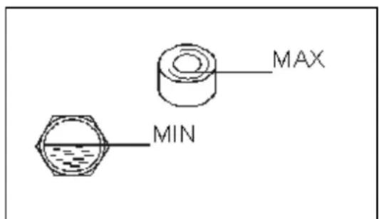
Figure 6
<= 15 KW
= 22 KW
Figure 7
EC-Declaration of Conformity
Fabricant: 63679 – Schotten, Germany
We hereby declare that the design and construction of the following described machines in their original factory configuration are in full conformity with the following list of EU guidelines, harmonized standards as well as other relevant technical standards:
Applied directives: 2004/108/EC, 2006/42/EC, 2006/95/EC, 2011/65/EC
Applied harmonized standards: EN 1012-1:1996, EN 60204-1:2006, EN 61000-6-2:2005, EN 61000-6-4-2007
Any unauthorised modifications to the machine nullify the validity of this declaration.
Description of machine: Compressor
Authorized person to compile the technical documentation :
63679 – Schotten, Germany
Schotten, Germany
Ort / Place / Lieu
Datum / Date / Date
Unterschrift / Signature / Signature CE-Officer
PREBENA
Description of machine: Compressor
Type of tool: SK-7,5-10
Type d'appareil:
TECHNISCHE DATEN
Füllleistung
1000 l/min
Supply voltage (input)
-400V\~
Line frequency
- 50 Hz
Electric protection, delayed-action
-15.6A
Power input
-7500W
Max. operating speed
- 5900 rpm
Vessel Capacity
-2701
Oil quantity 1
-4.81
Dimensions L x W x H
- 1300 x 680 x 1585 mm
Weight
- 345 kg
Compression final pressure
- 10 bar
Noise characteristics
- LpA = 72 dB (A)
Implementation temperature
- + 5irc C to +40irc C
Min. distance to wall
- 50cm
1 Lubricant recommended
PREBENA Special- Synthetic -Oil
Order no.: Z200.80
DONNÉES TECHNIQUES
Dimensions L x L x H
- 1300 x 680 x 1585 mm
Poids
- 345 kg
Pression finale de compression
- 10 bar
Type of tool: SK-15-10
Type d'appareil:
TECHNISCHE DATEN
Füllleistung
- 1900 l/min
Supply voltage (input)
-400V\~
Line frequency
- 50 Hz
Electric protection, delayed-action
-29.3A
Power input
- 15000 W
Max. operating speed
- 6060 rpm
Vessel Capacity
-5001
Oil quantity 1
-5.51
Dimensions L x W x H
- 2015 x 680 x 1585 mm
Weight
- 490 kg
Compression final pressure
- 10 bar
Noise characteristics
- LpA = 77 dB (A)
Implementation temperature
-+5°C to +40°C
Min. distance to wall
- 50cm
1 Lubricant recommended
PREBENA Special- Synthetic -Oil
Order no.: Z200.80
DONNÉES TECHNIQUES
Dimensions L x L x H
- 2015 x 680 x 1585 mm
Poids
- 490 kg
Pression finale de compression
- 10 bar
Notizen – notes - notes:


- Abbildung 7
- Schotten, Germany
- PREBENA
- TECHNISCHE DATEN
- DONNÉES TECHNIQUES
- Contents
- Appendix
- General information
- Scope of delivery
- Safety information
- Do not remove the plug during operation
- The operator must read the instructions
- Ensure that all moving parts, protective equipment and covers are securely held in place
- Start / Stop button
- Noise characteristic value
- Purpose
- Specifications
- NOTE: THE BUILT-IN ELECTRIC MOTOR HAS AN EFFICIENCY RATING OF IE2 FOR INSTALLATION IN A COMPRESSOR.
- Commissioning
- General information
- Commissioning of the pressure vessel
- Installation
- DO NOT OPERATE THE COMPRESSOR IN LOCATIONS WITH RISK OF EXPLOSION OR FIRE!
- DO NOT OPERATE THE COMPRESSOR IN RAIN!
- Mounting of the rubber shock absorbers (compressors without boiler only)
- DO NOT PERMANENTLY MOUNT THE COMPRESSOR TO THE FLOOR OR THE BASE PLATE!
- Connection to an air system
- Connection for secondary use of the emitted thermal energy
- Connection to the power supply
- Schematic circuit diagrams for the compressors can be found in Appendix E.
- Functions and operation
- Functions
- Functional principle
- Compressor unit protection devices
- Operation
- AirMaster P1 Controller
- Specifications
- THE EMERGENCY STOP SWITCH CAN ONLY BE PRESSED IN AN EMERGENCY!
- DANGER: IN THE EVENT OF THE FAILURE OF A PHASE (40s OR MORE) AND IN CASES OF UNDERVOLTAGE (UNDER 19.8 VAC) THE CONTROLLER SWITCHES THE COMPRESSOR OFF!
- Controller display
- Controller keys
- Functional Description
- Indications on the display
- Service Countdown Timers
- Menu access
- Initial commissioning
- DANGER: BEFORE INITIAL COMMISSIONING:
- Switching on the compressor
- Switching off the compressor
- Monitoring and control processes in the operating sequence
- Maintenance
- Ordering of spare parts
- Maintenance instructions
- Checking the oil level
- Recommended types of oil
- Manufacturer Type of oil
- Oil Change
- Cap for draining oil
- Oil filler neck
- Replacement of the belt
- Checking the belt tension
- Checking the intake filter (filter element)
- DANGER: IF THE AIR IS MIXED WITH ORGANIC AND MINERAL DUST OR CORROSIVE CHEMICAL VAPOUR, THE COMPRESSOR MUST BE IMMEDIATELY SUPPLIED WITH CLEAN / FILTERED AIR.
- Replacement of suction filter (filter element)
- Oil filter change
- Replacement of the oil separator
- Condensate drainage
- Checking the connection tightness of the air line
- External inspection of the compressor
- Checking the safety valve on the compressed air container (applies only to models with a compressed air tank)
- Troubleshooting and fault correction
- Transport, storage and disposal
- DO NOT SET UP UNDER OSCILLATING LOADS!
- Transport
- DANGER: WHEN USING A FORKLIFT, THE COMPRESSOR MUST BE ON A PALLET; IN ORDER TO PREVENT A FALL, SET THE FORKS TO AS SMALL A DISTANCE APART AS POSSIBLE!
- Storage
- CAUTION! PROTECT THE COMPRESSOR STORAGE LOCATION FROM ACID FUMES AND ALKALI, AGGRESSIVE GASES AND OTHER CONTAMINANTS
- Disposal
- DANGER: COMPRESSORS WITH AIR DRYERS: THE AIR DRYER CONTAINS A REFRIGERANT GAS AND OIL IN A CLOSED CIRCUIT. THE AIR DRYER MUST BE DISMANTLED AND DISPOSED OF BY AN AUTHORIZED ORGANIZATION (OR PERSON).
- Warranty
- Certificate of warranty
- Table des matières
Brand : Prebena
Model : SK 15-10
Category : Compressor