
UT132E - Multimeter Clas Ohlson - Free user manual and instructions
Find the device manual for free UT132E Clas Ohlson in PDF.


| Product type | Digital Multimeter |
| Brand | Clas Ohlson |
| Model | UT132E |
| Installation category | CAT II |
| Overvoltage protection | 600 V |
| Contamination level | 2 |
| Display | LCD, 2000 count |
| Power supply | 1 × 9 V battery (6F22) |
| Auto shut-off | After 15 minutes inactivity |
| Dimensions (L×W×H) | 137 × 72 × 35 mm |
| Weight (incl. battery) | Approx. 200 g |
| DC voltage measurement | 2000 mV, 20 V, 200 V, 600 V (±0.5% to ±0.8%) |
| AC voltage measurement | 200 V, 600 V (±1.2% + 3), 45–400 Hz |
| DC current measurement | 2000 μA, 20 mA, 200 mA, 10 A (±1% to ±2%) |
| Resistance measurement | 200 Ω to 20 MΩ (±0.8% to ±1%) |
| Diode test | Forward voltage drop, range 0–2.5 V |
| Continuity test | Buzzer sounds for resistance < 70 Ω |
| Temperature measurement | -40 °C to 1000 °C (built-in sensor up to 230 °C) |
| Battery test | 1.5 V and 9 V batteries under load |
| Backlight | Yes, toggleable |
| Overload protection fuses | 500 mA F 600 V and 10 A F 600 V (6.35×31.8 mm) |
| Input impedance (voltage) | ≥ 10 MΩ (≥ 3000 MΩ on mV range) |
| Operating environment | 0 °C to 40 °C, humidity ≤75% (≤50% above 30 °C) |
| Storage environment | -10 °C to 50 °C, humidity ≤75% (≤50% above 30 °C) |
| Maximum operating altitude | 2000 m |
| Package contents | Multimeter, 2 test leads, multi-purpose socket with temperature sensor, user manual |
| Care and maintenance | Wipe with damp cloth; do not use solvents |
| Disposal | Follow local regulations |
Frequently Asked Questions - UT132E Clas Ohlson
User questions about UT132E Clas Ohlson
0 question about this device. Answer the ones you know or ask your own.
Ask a new question about this device
Download the instructions for your Multimeter in PDF format for free! Find your manual UT132E - Clas Ohlson and take your electronic device back in hand. On this page are published all the documents necessary for the use of your device. UT132E by Clas Ohlson.
USER MANUAL UT132E Clas Ohlson
Please read the entire instruction manual before using the product and then save it for future reference. We reserve the right for any errors in text or images and any necessary changes made to technical data. If you have any questions regarding technical problems please contact our Customer Services.
Table of Contents
- Information about the meter ....4
1.1 Categorisation......4
1.2 Contamination level....4 - Safety instructions....5
- Package contents......6
- Functions ......6
- Operating instructions....7
5.1 Voltage measurement....7
5.2 DC current measurement ....8
5.3 Resistance measurement....9
5.4 Diode testing....10
5.5 Continuity measurement ....11
5.6 Taking temperatures....12
5.7 Battery test....12
5.8 Backlight 13
5.9 Sleep mode (automatic shut-off)....13 - Changing the battery....13
- Fuses....14
7.1 Checking the fuses....14
7.2 Changing the fuses....14 - Care and maintenance ....15
- Disposal 15
- General specifications....15
- Electrical specification ....16
11.1 Voltage measurement....16
11.2 DC measurement ....16
11.3 Resistance measurement....16
11.4 Temperature measurement....17
11.5 Battery test....17
11.6 Diode test and continuity test....17
1. Information about the meter
The multimeter has been designed and tested in accordance with the requirements for installation category II up to nominal voltages of 600 V and a contamination level of 2.
1.1 Categorisation
Meters are divided into different categories depending on the electrical environment in which they are to be used and how safe/protective they are in the event of a voltage surge.
The meter label should indicate which category it belongs to. The categorisation also determines how safe the instrument is with regards to any overvoltage which could represent a hazard for the user.
The categorisation is described briefly below:
In the event of a voltage surge in the electricity grid (a transient from a lightning strike, etc.), the risk will be greatest where the mains supply cable enters the building, for example. Further inside the building, the resistance (impedance) in the cables will increase and connected devices will reduce and dissipate the overvoltage. The meter category will therefore determine which electrical environment the instrument is designed to be used in.
The categories which meters are divided into are as follows:
- Category I: For measuring electronics and products that have inbuilt protection against voltage surges.
- Category II: For measuring single-phase equipment which is fed via the building's electrical power supply system. Both plug-connected and permanently installed.
- Category III: For measuring the building's electrical systems. Permanently installed cables, sockets, fuse boxes and switchgear cabinets. Three-phase distribution (all power supply cables and three-phase equipment, machinery and appliances).
- Category IV: Three-phase at primary level and all conductors for outdoor use.
This multimeter belongs to installation category II and is intended for measuring voltages of up to 600 V in single-phase products. The meter must not be used for measuring three-phase products, three-phase conductors or switchgear cabinets even if the nominal voltage does not exceed 600 V.
1.2 Contamination level
The meter is designed for use in environments in which contaminants which do not conduct electricity are present. With the exception that temporary conductor contamination can occur due to condensation.
Examples of environments with contamination level 2 are home environments in dry rooms, offices, test stations and laboratories. In other words, rooms which have a normal indoor climate.
The meter must not be used or stored in rooms where it could be exposed to electrically conductive contaminants in any form (solid, liquid or gas).
The meter should for example not be exposed to relative humidities in excess of 75% or used in unheated rooms and must not be used in wetrooms or outdoors where it could get wet.
It is not intended for use with electrical equipment which is used in industry or agriculture.
2. Safety instructions
- The multimeter has been tested in accordance with the EMC Directive 2004/108/EC and the Low Voltage Directive 2006/95/EG, and fulfils installation category (overvoltage category) II 600 V, contamination level 2 in accordance with EN 61010-1:2010 and EN61010-031:2002/A1:2008
- The meter is designed for indoor use at operating temperatures in the range 0–40°C.
- Make sure that the meter is used safely by following all safety instructions and operating directions.
- Do not use this meter if it or the test leads appear to be damaged, or if you suspect that the meter might not be working properly.
- Make sure that your fingers are behind the finger guards when using the test leads.
- Make sure that the power is turned off before working on power circuits. Even low voltages can be dangerous!
- Do not measure voltages higher than 600 VDC or 600 VAC RMS using the meter.
- To avoid shocks you need to be CAREFUL when you work with voltage higher then 60 VDC or 30 VAC RMS. Voltages higher than this pose a risk of heavy electric shocks.
- Set the right measuring range using the selector before starting to measure and do not change the range whilst taking a measurement.
- Never use the meter if the battery cover is missing or the battery compartment is open.
- To avoid electric shocks and damage to the meter, do not exceed the meter's measurement limits. The guarantee is void if the multimeter is used incorrectly.
- This multimeter is protected by fuses, but they will not protect the instrument from all kinds of misuse.
- The meter must not be used or stored in hot/humid, explosive or flammable environments or close to strong magnetic fields.
- Replace the battery immediately if the battery warning symbols appears on the display. A weak battery can cause incorrect results and thereby pose a safety hazard.
- Neither the meter nor its accessories may be dismantled or modified in any way.
- Remove the battery from the meter if it is not to be used for an extended period.
- Turn the meter off after use.
- If the meter is placed close to a strong magnetic field, it might cause incorrect readings which can be corrected by removing the cause of the interference.
3. Package contents
- Multimeter
- 2 x test leads
- Multi-purpose socket and temperature sensor
- User manual
4. Functions
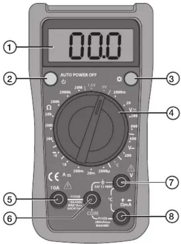
- LCD display
- [Power switch (ON/OFF)
- [☀] Backlight
- Multifunction selector with seven modes.
Test lead sockets:
- 10 A (DC current measurement up to 10A)
- COM (common return for the black test lead)
- V (voltage measurement)
- Ω mA (DC measurement up to 0.2 A, resistance measurement, diode test, continuity measurement and temperature measurement).
5. Operating instructions
Warning!
- Before measuring voltage, always ensure that the meter is set to the correct function range and not set to current, resistance or diode test measurement. Always ensure that you use the correct test lead socket for the type of measurement to be made.
- Use extreme caution when measuring voltages over 60 V, especially when the circuit being measured has a high power output.
- Make sure that the circuit to be measured is not "live", i.e. conducting any current, before connecting test leads in series with it (such as when measuring current).
- Make sure that the circuit to be tested is not conducting any current before performing resistance measurements or diode tests.
- Always ensure that the correct function and range are selected. If in doubt about the correct range, start with the highest and work downwards.
- Take extreme care when using the meter on an inductive component such as a transformer, relay coils and the like. High voltage may be induced at the measuring points if an open circuit occurs.
• Make sure that the test leads are in good condition with no damage to the insulation. - If you replace the fuse, make sure that it is the correct type and rating.
5.1 Voltage measurement
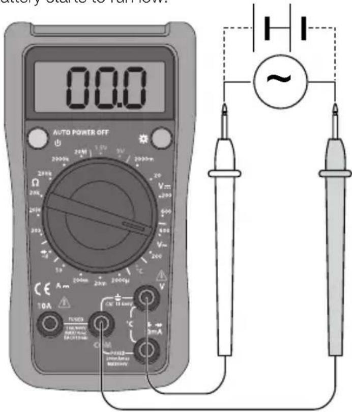
Check the battery by rotating the multifunction selector to a new measuring function. The battery symbol will appear if the battery starts to run low.
- Connect the black test lead to COM and the red test lead to V.
- Set the function selector to V\~ (200–600 V\~) or V= (2000 mV – 600 V) and the required measuring range for voltage measurement.
- Switch on the multimeter using [⏻]
- Connect the test leads across the voltage source to be measured. Read the value.
- Switch of the multimeter using [∅].
Note: If the incorrect polarity is connected when measuring DC voltages, the display will show - (minus) before the reading.
Note:
In each range, the meter has an input impedance of 10 MΩ except the mV range, which has an input impedance of 3000 MΩ. This can cause measurement errors in high impedance circuits. If the circuit impedance is less than or equal to 10 kΩ, the error is negligible (0.1 % or less).
5.2 DC current measurement
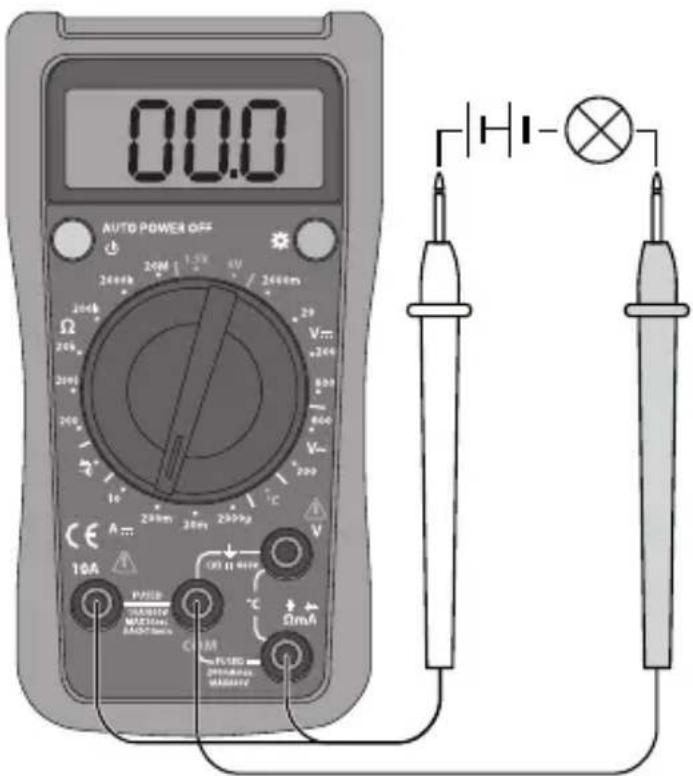
- Connect the black test lead to COM and the red test lead to mA (for 0–200 mA) or to 10A (for the range 200 mA – 10 A).
- Set the multifunction selector to A...
- Switch on the multimeter using [⏻].
- Connect the test leads in series with the current source to be measured. Read the value.
- Switch off the multimeter using [⏻].
Warning!
Do not connect the leads in parallel with the voltage source when measuring current!
If in doubt about the correct range, start with the highest and work downwards.
When measuring high currents, the meter should only be connected briefly (less than 10 seconds for currents over 5 A). This is to prevent the shunt in the instrument from overheating.
The interval between two readings must be greater than 15 minutes.
5.3 Resistance measurement
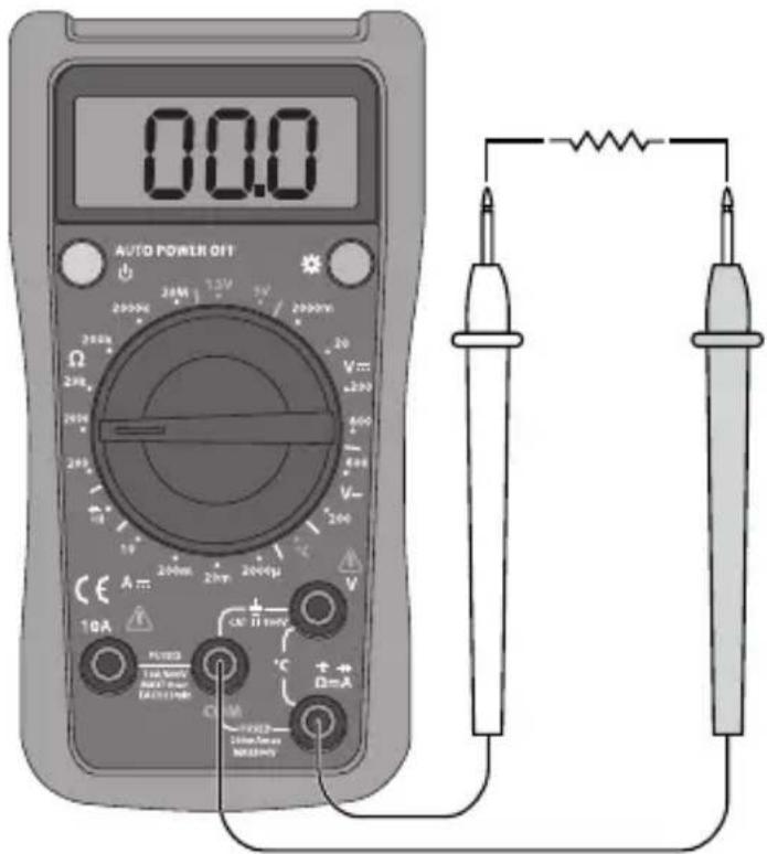
- Connect the black test lead to COM and the red test lead to .
- Set the multifunction selector to and the required range for resistance measurement.
- Switch on the multimeter using [↓].
- Connect the test leads across the circuit to be tested. Read the value.
- Switch off the multimeter using [∅].
Warning: Ensure that the circuit to be tested is not "live" before taking any measurements.
In order to avoid the risk of personal injury, never measure components with a voltage higher than 60 V (DC) or 30 V (AC).
The test leads can add 0.1–0.2 Ω to the actual resistance measured. To obtain accurate readings of low-resistance components, short-circuit the input sockets beforehand, record the short-circuited reading and use it to remove the lead resistance error from the reading on the display.
If the short-circuited reading is higher than 0.5 Ω, check whether any connection/test lead is loose or damaged.
For high-resistance measurement (>1 MΩ), it is normal for the reading to take several seconds to stabilize.
For maximum accuracy, leads that are of the highest possible quality and as short as possible should be used.
5.4 Diode testing
-
Connect the black test lead to COM and the red test lead to ✦
-
Set the multifunction selector to for measuring diode threshold value (V).
-
Switch on the multimeter using [⏻].
-
Connect the black test lead to the cathode and red test lead to the anode of the diode to be tested. Read the forward voltage drop value from the display. If "1" appears on the display, reverse the polarity of the diode.
-
Switch off the multimeter using [⏻].
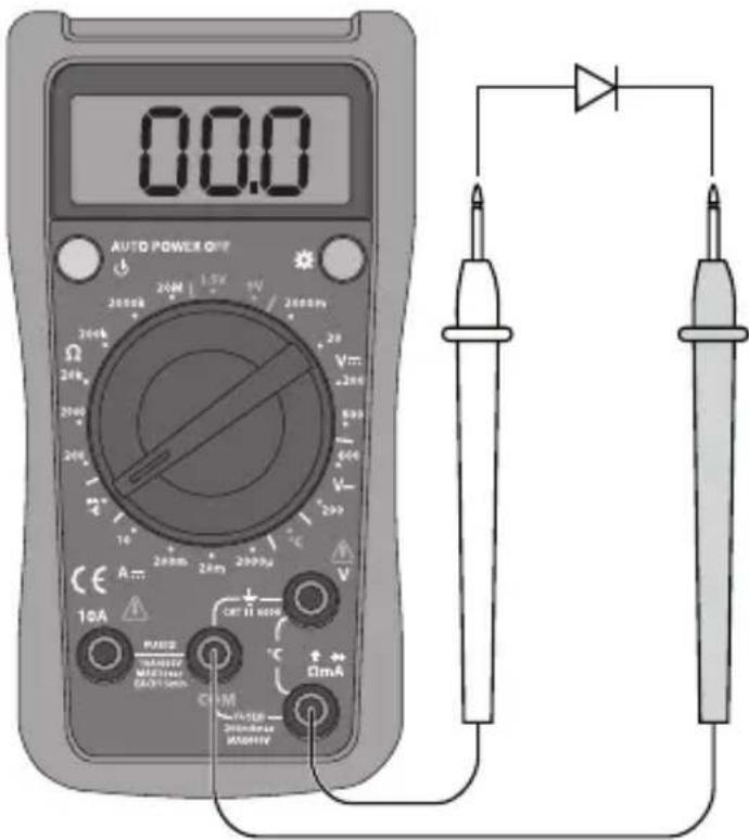
Warning!
Make sure that the circuit to be tested is not conducting any current before testing diodes.
Take extreme care when using this instrument on an inductive component such as a transformer, relay coils and the like, and make sure they have been discharged beforehand. High voltage may be induced at the measuring points if an open circuit occurs.
Note: A good diode should have a forward voltage drop of from 0.5 to 0.8 V. However, the reverse voltage drop reading can vary considerably depending on the resistance to other paths of conductance between the tips of the test leads.
5.5 Continuity measurement
- Set the multifunction selector to ·
- Connect the black test lead to COM and the red test lead to mA.
- Switch on the multimeter using [ ]
-
Connect the ends of the test leads to the ends of the cables to be tested.
-
No break in the cable: The buzzer sounds continuously if the resistance is < 10 .
-
Break in the cable: The buzzer does not sound if the resistance is >70 Ω.
-
Switch off the multimeter using [💡]
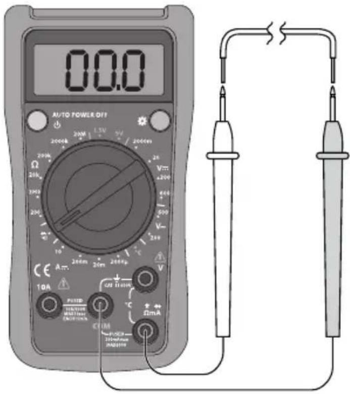
Warning!
Make sure that the circuit to be tested is not conducting any current before testing for continuity.
Take extreme care when using this instrument on an inductive component such as a transformer, relay coils and the like, and make sure they have been discharged beforehand. High voltage may be induced at the measuring points if an open circuit occurs.
To avoid shocks, you must be CAREFUL when working with voltages higher than 60 VDC or 30 VAC RMS. Voltages higher than this pose a risk of heavy electric shocks.
Note: The open-circuit voltage is around 2.3–2.5 V.
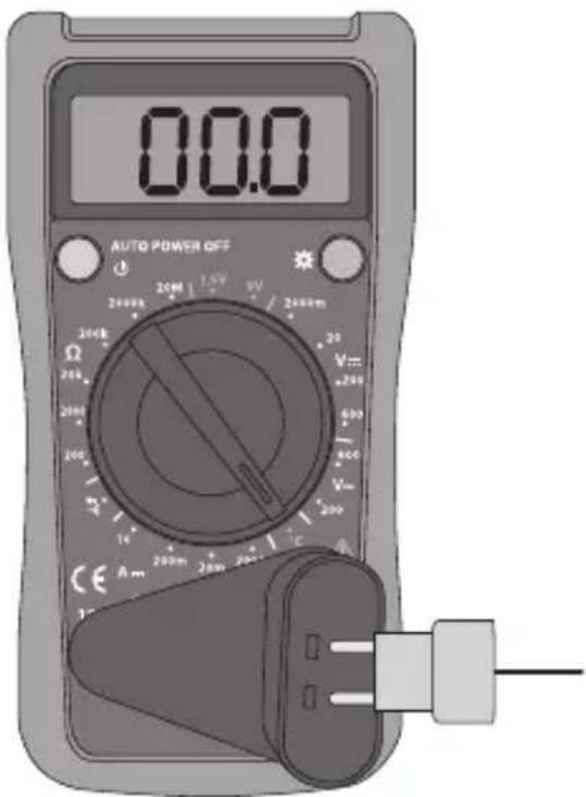
5.6 Taking temperatures
Note: Temperature measurement up to 230 °C with inbuilt temperature sensor.
At higher temperatures, a different type of temperature sensor must be used.
- Set the multifunction selector to °C.
- Connect the multi-function socket to the multimeter and the temperature sensor to the multi-function socket.
- Switch on the multimeter using [⏻].
- Place the temperature sensor next to the place to be measured.
- Read the value.
- Switch off the multimeter using [⏻].
5.7 Battery test
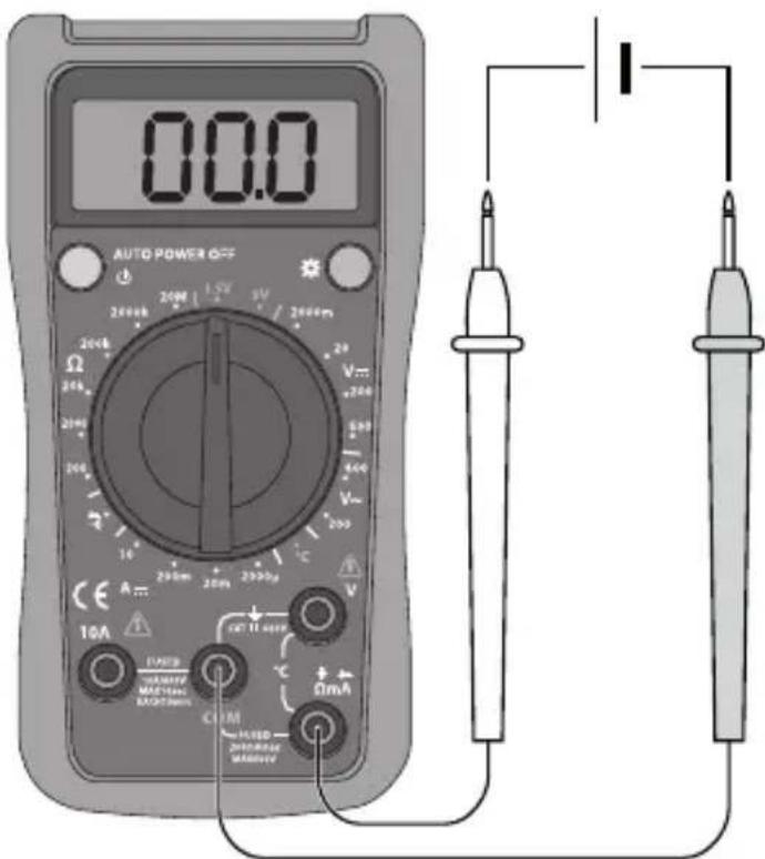
- Set the multifunction selector to 1.5 V or 9 V.
- Connect the black test lead to COM and the red test lead to mA.
- Switch on the multimeter using [⏻].
- Connect the test leads to the battery to be tested.
- Read off the battery's voltage under load.
- Switch off the multimeter using [⏻].
Meter load during measurement:
1.5 V battery approx. 10 Ω.
9 V battery approx. 1 kΩ.
The battery measurement is intended for 1.5 V and 9 V batteries only. Batteries with a higher voltage can damage the meter.
5.8 Backlight
Press [💡] to switch the backlight on or off.
5.9 Sleep mode (automatic shut-off)
To preserve battery life, the meter has an auto shut-off feature. If the multifunction selector is not turned within 15 minutes, the meter turns itself off automatically.
If sleep mode has been activated, switch on the meter by pressing [⏻] twice.
6. Changing the battery
Change the battery as soon as the battery symbol appears on the display.
Warning!
Make sure the test leads are disconnected from the circuit being tested before replacing the battery.
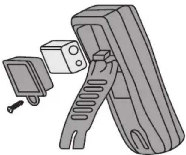
- Turn the meter off and remove the test leads.
- Unscrew the battery cover.
- Remove the battery cover.
- Remove the old battery and insert the new 9 V (6F22) battery, observing the correct polarity.
- First, press the lower half of the battery cover/stand over the battery and then screw it in place.
natural_image
Illustration of a mechanical device with a screw and a button, no text or symbols present7. Fuses
7.1 Checking the fuses
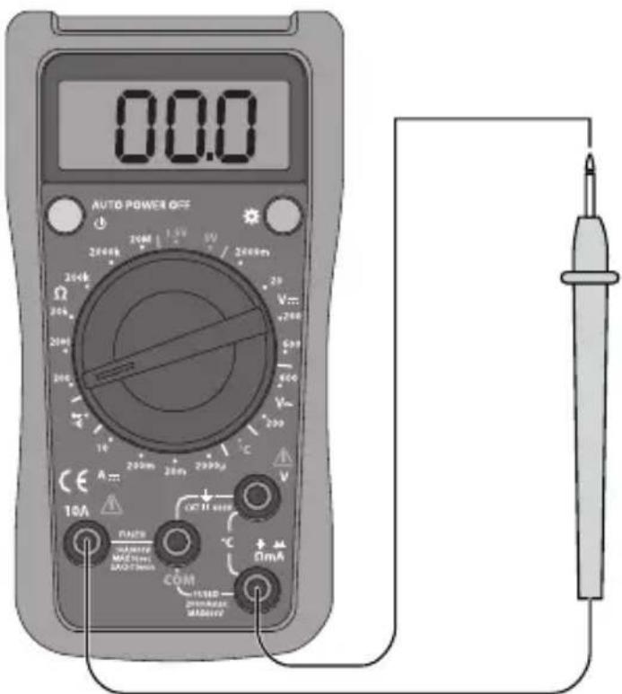
If the meter does not respond when measuring current, one of the fuses has probably blown. Checking the fuses:
- Set the function knob to range up to 200.
- Switch on the multimeter using [⏻].
- Connect one of the test leads between the 10 A and mA connections. It may take a little while for the value to stabilise. If the reading is 0.5 or lower, both fuses are whole.
- Switch off the multimeter using [💡].
7.2 Changing the fuses
The meter is protected by two fuses:
- 1 × fuse 500 mA F (fast blow) 600 V (6.35 × 31.8 mm).
-
1 × fuse 10 A F (fast blow) 600 V (6.35 × 31.8 mm).
-
Switch off the meter and remove the test leads.
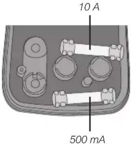
- Remove the three screws holding the casing together.
- Remove the battery cover.
- Remove the back of the meter to access the fuses.
- The upper fuse is 10 A and the lower one 500 mA.
- Replace the fuse with one of the identical type and specification.
- Replace the battery holder.
- Screw the casing together again.
Warning!
Switch off the meter and remove the test leads from the circuit being tested before replacing the fuses.
8. Care and maintenance
Switch off the multimeter before cleaning.
Wipe the meter with a moist, soft cloth. Use a mild detergent and never use solvents or strong, abrasive cleaning agents for cleaning as these can damage the meter.
9. Disposal
This product should be disposed of in accordance with local regulations.
If you are unsure what to do, contact your local authority.
10. General specifications
Polarity Automatic negative (-) polarity indication
Zero adjustment Automatic
Power supply 1 × 6F22 battery (9 V)
Overload protection 1 × fuse 500 mA F (fast blow) 600 V (6.35 × 31.8 mm)
1 × fuse 10 A F (fast blow) 600 V (6.35 × 31.8 mm)
Measurement update 2–3 times per second
Measurement range Manual mode
Battery warning The battery symbol is shown on the display
Operating environment 0 to +40 °C at humidity ≤ 75 % (up to +30 °C)
and ≤ 50 % (over +30 °C)
Storage environment -10 to +50 °C at humidity ≤ 75 % (up to +30 °C)
and ≤ 50 % (over +30 °C)
Max. operating altitude Up to 2000 m above sea level
Size (L × W × H) 137 × 72 × 35 mm
Weight (incl. batteries) approx. 200 g
11. Electrical specification
11.1 Voltage measurement
| Function Scale Resolution Accuracy(± a % reading, + b number of digits) | Description | |||
| DC 2000 m | V 1 mV ± (0.5 % + 2) Input impedance | ≥ 10 MΩ | ||
| 20 V 0.01V | ||||
| 200 V 0.1 V | ||||
| 600 V 1 V ± (0.8 % + 2) | ||||
| AC 200 V | 0.1 V ± (1.2 % +3) Input impedance 4.5 MΩ | Response: 45–400 Hz;Display: RMS of sine wave (mean value) | ||
| 600 V 1 V | ||||
11.2 DC measurement
| Function Scale Resolution Accuracy | (± a % reading, + b number of digits) | Overload protection | ||
| DC Current | 2000 μA 1 μA ± (1 % + 2) mA: 0,5 A fuse | 10A:10 A fuse | ||
| 20 mA 0.01 mA | ||||
| 200 mA | 0.1 mA | ± (1.2 % + 2) | ||
| 10 A | 0.01 A | ± (2 % + 5) | ||
Warning! ≤ 5 A continuous measurement. ≥ 5 A each measurement max.
10 seconds, 15 minutes between each measurement.
11.3 Resistance measurement
| Function | Scale | Resolution | Accuracy(± a % reading, + b number of digits) |
| Resistance measurement | 200 Ω | 0.1 Ω | ± (0.8 % + 5) |
| 2000 Ω | 1 Ω | ||
| 20 kΩ | 0.01 kΩ | ||
| 200 kΩ | 0.1 kΩ | ||
| 2000 kΩ | 1 kΩ | ||
| 20 MΩ | 0.01 MΩ | ± (1 % + 5) |
11.4 Temperature measurement
| Function Measuring | range | Resolution Accuracy(± a % reading, + b number of digits) |
| Measuring Temperature | - 40 to - 20 °C 1 °C | -8 % + 5 °C |
| -20–0 °C ± 4 °C | ||
| 0–100 °C ± (1.0 % + 3) | ||
| 100–1000 °C* ± (2.5 % + 2) |
* Note! Temperature measurement up to 230°C with inbuilt temperature sensor. At higher temperatures, a different type of temperature sensor must be used.
11.5 Battery test
| Function Measuring range Resolution Accuracy | ||
| Battery test 1.5 V 1 | 0 mV ± (1.0 % + 2) | |
| 9 V 10 mV | ||
Meter load during measurement: 1.5 V battery approx. 10 Ω. 9 V battery approx. 1 Ω.
11.6 Diode test and continuity test
| Function Scale | Resolution | Remark | |
| Measuring diodes | 1 mV | Shows approx. value for forward voltage drop | |
| Continuity | 1 Ω The buzzer sounds < 70 Ω | ||
Multimeter
Art.nr 36-5256 Modell UT132E
natural_image
Illustration of a mechanical device with a spring-loaded handle and a small rectangular component (no text or symbols)7. Säkringar
natural_image
Illustration of a mechanical device with a spring-loaded handle and a small box, no text or symbols present.7. Sikringer
natural_image
Illustration of a remote control device with a sensor and screw, showing no text or symbols.7. Sulakkeet
7.1 Tarkista sulakkeet
natural_image
Illustration of a handheld device with a small inset showing a button and screw, no text or symbols present.7. Sicherungen
Postal 10 – 13 Market Place
Kingston Upon Thames
Surrey
KT1 1JZ
Deutsch


- Table of Contents
- Information about the meter
- Categorisation
- Contamination level
- Safety instructions
- Package contents
- Functions
- Test lead sockets:
- Operating instructions
- Warning!
- Voltage measurement
- Note:
- DC current measurement
- Resistance measurement
- Diode testing
- Continuity measurement
- Taking temperatures
- Battery test
- Backlight
- Sleep mode (automatic shut-off)
- Changing the battery
- Fuses
- Checking the fuses
- Changing the fuses
- Care and maintenance
- Disposal
- General specifications
- Electrical specification
- Voltage measurement
- DC measurement
- Resistance measurement
- Temperature measurement
- Battery test
- Diode test and continuity test
- Multimeter
- Säkringar
- Sikringer
- Sulakkeet
- Tarkista sulakkeet
- Sicherungen
- Deutsch
Brand : Clas Ohlson
Model : UT132E
Category : Multimeter