
UNI-T UT133B - Multimeter Clas Ohlson - Free user manual and instructions
Find the device manual for free UNI-T UT133B Clas Ohlson in PDF.


| Product Type | Digital Multimeter |
| Brand | Clas Ohlson |
| Model | UNI-T UT133B |
| Dimensions | 155 × 76.5 × 49 mm |
| Weight | 255 g (including batteries) |
| Power Supply | 2 × AAA/LR03, 1.5 V batteries |
| Display | Backlit LCD, 56.8 × 36.1 mm |
| Safety Rating | CAT III 600 V, Pollution Degree 2 |
| DC Voltage Ranges | 600.0 mV to 600.0 V |
| AC Voltage Ranges | 600.0 mV to 600.0 V |
| DC Current Ranges | 600.0 μA to 10.00 A |
| Resistance Ranges | 600.0 Ω to 60.00 MΩ |
| Capacitance Ranges | 9.999 nF to 9.999 mF |
| Special Functions | NCV, Diode test, Continuity test, Battery test (1.5 V/9 V), Data Hold, Auto Power Off |
| Fuse Protection | 1 × 10 A, 600 V BFC; 1 × 600 mA, 600 V BFC |
| Operating Temperature | 0–40 °C (32–104 °F) |
| Storage Temperature | -10 to +50 °C (14–122 °F) |
| Maximum Altitude | 2000 m |
| Cleaning Instructions | Wipe with a damp cloth; use mild detergent only |
| Repairability | Replaceable batteries and fuses |
Frequently Asked Questions - UNI-T UT133B Clas Ohlson
User questions about UNI-T UT133B Clas Ohlson
0 question about this device. Answer the ones you know or ask your own.
Ask a new question about this device
Download the instructions for your Multimeter in PDF format for free! Find your manual UNI-T UT133B - Clas Ohlson and take your electronic device back in hand. On this page are published all the documents necessary for the use of your device. UNI-T UT133B by Clas Ohlson.
USER MANUAL UNI-T UT133B Clas Ohlson
UNI-T UT133B Multimeter
Multimeter UNI-T UT133B UNI-T UT133B multimeter Yleismittari UNI-T UT133B
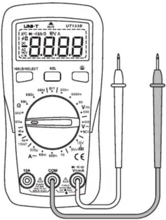
Art.no. Model
36-7745 UT133B
Ver. 20190705
UNI-T Multimeter
Art.no
36-7745
Model
UT133B
Please read the entire instruction manual before using the product and then save it for future reference. We reserve the right for any errors in text or images and any necessary changes made to technical data. In the event of technical problems or other queries, please contact our Customer Services (see address details on the back).
Information about this measuring instrument
This multimeter has been constructed and tested in accordance with the requirements of Measurement Category III (CAT III) up to 600 V nominal voltage and Pollution Degree 2.
Categorisation
Measuring instruments are classified into categories according to what kind of electrical environment they can be used in and how safe/protective they are at withstanding overvoltages.
The Measurement Category of the instrument will be marked on the rating plate.
The Measurement Category indicates how capable the instrument is of withstanding overvoltages which could be dangerous for the user.
In brief, the categorisation can be described like this:
- In the event of a sudden overvoltage on the power grid (a transient energy spike from a lightning strike for example) the danger is greatest at the point where the power supply service cable enters a building.
- Further in the building, the resistance (impedance) in the mains supply cables increases and connected appliances and devices reduce and divide the overvoltage. Therefore, the Measurement Category (also called Overvoltage Installation Category) of the measuring instrument indicates which electrical environment the instrument is designed to be used in.
The categories that measuring instruments are classified into are:
- CAT I: For measuring electronics and products that have a built-in protection from overvoltage.
- CAT II: For measuring single-phase equipment connected to a household mains supply, both through wall sockets and fixed installation.
- CAT III: For measuring electrical wiring installed in buildings. Examples are measurements on fixed installation cables and hard-wired appliances, socket outlets, circuit breakers and distribution boards. Three-phase distribution (all supply cables and 3-phase equipment, machines and appliances).
- CAT IV: Three-phase at the utility connection and any outdoor conductors.
This multimeter is rated as CAT III and is approved for measuring voltages up to 600 V on single-phase products. This multimeter must not be used for measuring three-phase equipment, three-phase cables or distribution boards even if the nominal voltage is not higher than 600 V.
Pollution degree
This multimeter is constructed to be able to be used in environments which contain pollutants which are not electrically conductive, with the exception of temporary conductivity caused by condensation.
Examples of environments with Pollution Degree 2 are dry home or office environments, test stations and laboratories. Basically, any dry environment with normal indoor climatic conditions.
The multimeter must not be used or stored in a location where it can be exposed to electrically conductive pollution of any kind (solid, liquid or gas).
The multimeter should not be exposed to relative humidity over 75 %, be used in unheated rooms and must not be used in bathrooms or outdoors where it might get wet.
It is not designed to be used with electrical equipment used in industry or agriculture.
Safety
- The product conforms to the following CE standards: EN 611010-1:2010, EN 61010-2-030:2010, EN 61326:2013, and CAT III: 600 V, Pollution Degree 2.
- Make sure that the product is used safely by following the safety instructions and operating directions in this instruction manual.
- Neither the product nor its accessories must be dismantled or modified in any way.
- The product must never be used if it is in any way damaged or malfunctioning.
- Make sure that the power is turned off before working on the power circuit. Low current levels can also be dangerous.
- Make sure that your fingers are behind the finger guards when using the test leads.
- To avoid electric shocks and damage to the product, do not exceed the product's overload limits.
- Do not measure voltages higher than 600 V DC or 600 V AC RMS using this product.
- To avoid shocks you need to be very CAREFUL when you work with voltage higher than 60 V DC or 35 V AC RMS. Voltages higher than this pose a risk of harmful electric shocks.
- Never use the product if the battery cover is missing or the battery compartment is open.
- Replace the batteries as soon as the battery warning symbol appears on the display, low batteries can cause an incorrect reading and constitute a safety hazard.
- Set the right measuring range using the selector before starting to measure and do not change the range whilst taking a measurement.
- The product is protected by fuses, but they will not protect the meter from all kinds of misuse.
- The product must not be used in humid, explosive or flammable environments or close to strong magnetic fields.
- Remove the battery if the device is not to be used for an extended period.
- Turn the product off after use.
- If the product is placed close to a strong magnetic field it might cause incorrect readings which can be corrected by removing the cause of the interference.
Buttons and functions
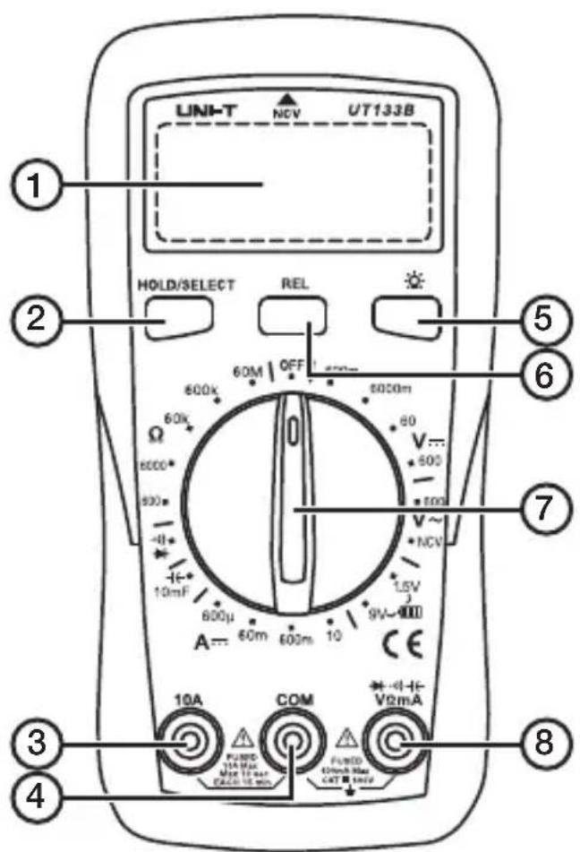
- Display
- [HOLD/SELECT] Press this key to hold a reading, to change between diode mode and continuous buzzer and deactivate APO.
- 10A: Connection for the red test lead when measuring DC current up to 10 A.
- COM: Connection for the black test lead (common/return).
- [ ] Press to switch the display light on/off. The light goes off automatically after 30 seconds if not switched off.
- [REL] Relative mode, ▲ appears on the display (only for capacitance measurements).
- Function selector switch
- VΩmA: Connection for red test lead when measuring voltage, measuring DC current up to 0.2 A, measuring resistance, testing diodes, measuring continuity and measuring temperature.
Display symbols
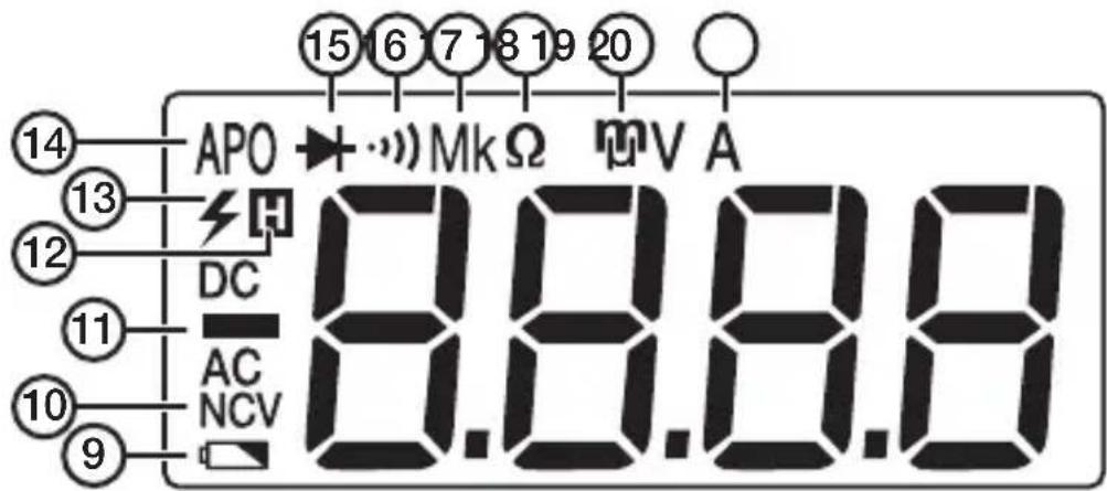
- : Low battery warning, change batteries (2 × AAA/LR03, 1.5 V).
- NCV: (Non-contact voltage) For measuring electromagnetic fields.
- AC/DC: alternating current/direct current
- H: Indicates that the HOLD function is activated.
- : High voltage warning.
- APO: Auto power off, the display switches off automatically after 15 minutes.
- : Diode test mode (change using the [ HOLD/SELECT ] button).
- : Buzzer mode (change using the [ HOLD/SELECT ] button).
- Decimal prefix for resistance measurements.
- Ω: Resistance measurement
- Decimal prefix for voltage and direct current measurements.
- A: Direct current measurement.
OL (overload) Appears when the reading exceeds the selected measuring range.
Instructions for use
APO
When APO (Auto power off) is activated, the multimeter shuts off after 15 minutes of inactivity.
- APO mode is activated automatically when the multimeter is switched on.
- To deactivate APO mode: Hold in [ HOLD/SELECT ] and turn the function selector from "off" to any other position.
- If the APO mode is deactivated during a long measurement, the meter will need to be switched off manually.
Backlight
Press [-] Do switch the backlight on/off. The backlight shuts off automatically after 30 seconds of inactivity.
AC/DC Voltage measurements

Warning
- When measuring voltage always ensure that the multimeter is switched to the correct measuring range and not set to the current, resistance or diode test range.
- Use extreme caution when measuring voltages over 60 V, especially when the object being measured has a high power output.
• High voltage may be induced at the measuring points when the circuit is broken. - Always ensure that the correct function and range is selected. If in doubt about the correct range, start with the highest and work downwards.
- Make sure that the test leads are in good condition with no damage to the insulation.
-
Always ensure that you use the correct test lead terminal for the type of measurement to be made.
-
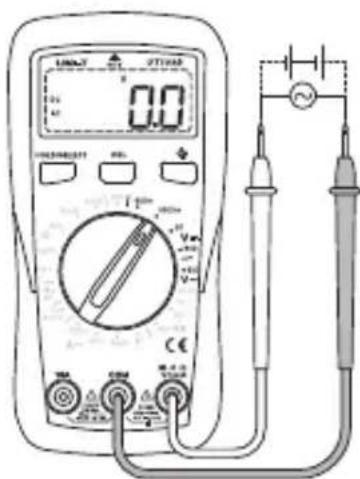
Connect the black test lead to COM and the red lead to VΩmA.
- Set the function selector to 600 V\~ (AC, alternating current) or 600 mV - 600 V —— (DC, direct current).
- Connect the test leads to the circuit to be tested and read the value.

Information
If the wrong polarity is connected when measuring direct current, a minus sign (−) will be displayed in front of the value.
NCV
NCV (Non-contact voltage) is a measuring mode that can be used to measure the voltage of power sockets, cables and other components through their electromagnetic fields without making physical contact with them.

Warning
• The NCV function is not intended to be used to measure shielded equipment.
- Even if the meter does not indicate an electromagnetic field, you should always make sure that the power is turned off before working on the circuit. Low current levels can also be dangerous.
- If the Phase (Live) and Neutral conductors are close to each other, it might be impossible to determine which of them is which.
- If there are several cables with 2-phase or 3-phase cables close to one another, try to separate them and measure each cable individually.
- Electrical cables consist of 2 or more conductors and only some of the conductors might be carrying current at the time of the measurement. Therefore, always measure all conductors in a cable to get a correct value.
-
The NCV function only works when measuring AC (alternating current), not DC (direct current).
-
Set the function selector to NCV, "EF" will appear on the display.
- Hold the top of the multimeter (marked "NCV" with an arrow on top) close to the test subject.
- The voltage will be represented by a number of dashes “-” on the display:
The table only provides an approximate value, for more exact values it is recommended that the test leads be used.
- When "Bad" appears on the display, the battery needs to be replaced.
-
If the battery is under 0.2 V, only a flashing "Good", "Low" or "Bad" will be displayed.
-
Connect the black test lead to COM and the red lead to VΩmA.
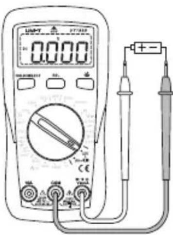
- Set the function selector to 9 V or 1.5 V depending on the type of battery you wish to test.
- The status of the tested battery is described on the display as either "Good", "Low" or "Bad":
| Battery model 1.5 V | 9 V | |
| Load resistance | 30 Ω900 Ω | |
| Good ≥ 1.31 V ≥ 7.8 V | ||
| Low 0.95–1.31 V 5.7–7.7 V | ||
| Bad ≤ 0.94 V ≤ 5.6 V |
DC current measurement

Warning
- Do not connect the test leads in parallel with the voltage source when measuring current!
- If in doubt about the correct measuring range, start with the highest and work downwards.
- When measuring high currents, the multimeter should only be connected briefly (less than 30 seconds for currents greater than 10 A).
- The interval between two readings must be greater than 15 minutes.
• Make sure that the test leads are in good condition with no damage to the insulation.
- Always ensure that you use the correct test lead terminal for the type of measurement to be made.
- When measuring voltage always ensure that the multimeter is switched to the correct measuring range and not set to the current, resistance or diode test range.
- Make sure that the object to be measured is not energised (conducting any current) before connecting test leads in series with it (such as when measuring current).
-
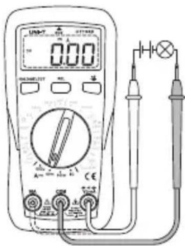
Connect the black test lead to COM and the red to VΩmA (for measuring 0–200 mA) or to 10A (for measuring between 200 mA and 10 A).
-
Set the function selector switch to A ---
-
Connect the test leads in series with the load and source of the current to be measured.
Capacitance measurement

Warning
Make sure that the circuit to be tested is not energised and that any high-voltage capacitors have been discharged before performing capacitance measurements.
-
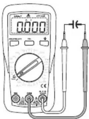
Connect the black test lead to COM and the red lead to VΩmA.
-
Set the function selector to +←.

Information
The accuracy of readings can be improved by using the relative readings modifier ([REL]) function to subtract the residual capacitance of the meter and the test leads.
Diode testing

Warning
Make sure that the circuit to be tested is not energised and that any high-voltage capacitors have been discharged before performing diode measurements.
-
Connect the black test lead to COM and the red test lead to VΩmA.
-
Set the function selector switch to

-
Press the [HOLD/SELECT] button to toggle between buzzer mode and diode test mode.
-
Connect the black test lead to the cathode (negative end) and red test lead to the anode (positive end) of the diode to be tested.
-
Read the forward voltage drop value from the display.
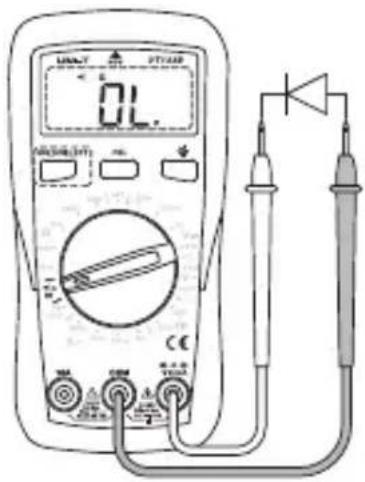
If L is displayed, the diode is either open or the polarity is reversed. Try reversing the polarity of the diode. The normal value for a P–N junction is about 500–800 mV (0.5–0.8 V).
Continuity test

Warning
Make sure that the circuit to be tested is not energised and that any high-voltage capacitors have been discharged before performing continuity tests.
-
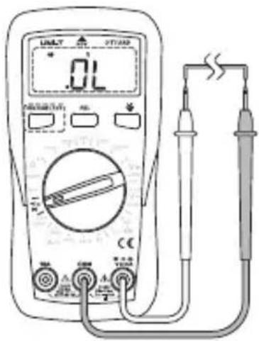
Connect the black test lead to COM and the red test lead to VΩmA. Set the function selector switch to .
-
Connect the ends of the test leads to the ends of the cables to be tested.
- No break in the cable: The buzzer sounds continuously if the resistance in the cable is ≤ 10 .
- A break in the cable: The buzzer does not sound if the resistance in the cable is > 50 Ω.
Resistance measurement

Warning
- Make sure that the circuit to be tested is not energised and that any high-voltage capacitors have been discharged before performing resistance measurements.
- Be extremely cautious when using this instrument on an inductive component such as a transformer, relay coil and the like, and make sure it has been discharged beforehand. High voltage may be induced at the measuring points when the circuit is broken.
-
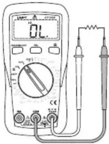
Connect the black test lead to COM and the red lead to VΩmA.
-
Set the function selector switch to and the preferred range for measuring resistance.
-
Connect the test leads across the circuit to be tested.
Care and maintenance
- Clean the exterior of the multimeter by wiping it with a damp cloth. Use only mild cleaning agents, never solvents or corrosive chemicals.
- Whenever the multimeter is not to be used for an extended period, the battery should be removed and it should be stored in a dry, dust-free environment, out of children's reach.
Battery replacement
-
Disconnect the test leads.
-
Turn the function selector switch to OFF.
-
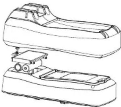
Remove the protective plastic cover.
-
Undo the screw and remove the battery cover.
-
Take the batteries out of the battery compartment.
-
Insert new batteries (2 × AAA/LR03). Refer to the markings in the battery compartment to ensure correct polarity.
-
Refit the battery cover and tighten the screw.
-
Refit the protective plastic cover.
natural_image
Technical line drawing of a mechanical device with two views (top and side), no text or symbols present.Replacing the fuses
If you replace one or both of the fuses, make sure that the replacement fuse is the correct type and rating.
When it appears on the display and the buzzer sounds, it is time to check the fuses.
- Disconnect the test leads from the multimeter.
- Turn the function selector switch to OFF.
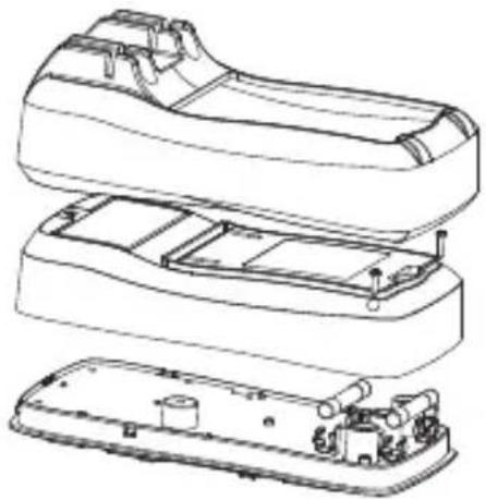
- Remove the protective plastic cover.
- Unscrew the two screws holding the back panel and remove it.
- Replace the fuse/fuses with equivalent fuses to the one/s you remove:
- 1 × 10 A, 600 V, BFC (fast-blow ceramic), 6 × 25 mm
- 1 × 600 mA, 600 V, BFC (fast-blow ceramic), 6 × 32 mm
natural_image
Exploded view diagram of a device showing internal components (no text or labels)- Put the battery cover back on and tighten the screws.
Responsible disposal
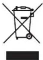
This symbol indicates that the product should not be disposed of with general household waste. This applies throughout the entire EU. In order to prevent any harm to the environment or health hazards caused by incorrect waste disposal, the product must be handed in for recycling so that the material can be disposed of in a responsible manner. When recycling your product, take it to your local collection facility or contact the place of purchase. They will ensure that the product is disposed of in an environmentally sound manner.
natural_image
Symbol of a trash bin with crossed lines indicating no waste or discharge, and a solid black rectangle below (no text or labels)Specifications
Power supply 2 × AAA/LR03, 1.5 V batteries
Fuses 1 × 10 A, 600 V, BFC (fast-blow ceramic), 6 × 25 mm 1 × 600 mA, 600 V, BFC (fast-blow ceramic), 6 × 32 mm
Test leads Test leads with probes included
Operating environment 0–40 °C (32–104 °F) 0–30 °C, ≤75 % humidity 30–40 °C, ≤50 % humidity
Storage environment -10 to +50 °C (14–122 °F)
Max operating altitude 2000 m
Dimensions 155 × 76.5 × 49 mm
Screen size 56.8 × 36.1 mm
Weight 255 g (incl. batteries)
Technical specifications
Measuring range Manual selection
Battery tester 1.5 V and 9 V
Diode test
Continuous buzzer
NCV
Backlit display screen
[Hold] saves the reading
Low battery warning Battery symbol is shown on the display
Overload indication
OL (overload) is shown on the display
DC Voltage
| Range Resolution Accuracy | ||
| 600.0 mV 0.1 mV ±(0.7 % + 3) | ||
| 6.000 V / 6000 mV 0.001 V / 1 | mV ±(0.5 % + 2) | |
| 60.00 V 0.01 V ±(0.7 % + 3) | ||
| 600.0 V 0.1 V ±(0.7 % + 3) |
Input impedance: Approximately 10 MΩ.
The readings might fluctuate when measuring mV if there is no current in the circuit. The reading will stabilise once the circuit has current. Accurate to the least significant digit ≤ ± 3 .
Max input voltage: ± 600 V, when the voltage exceeds 610 V, OL appears on the display and the buzzer sounds. Overload protection: 600 Vrms DC
AC Voltage
| Range Resolution Accuracy | ||
| 600.0 mV 0.1 mV ±(1.0 % + 3) | ||
| 6.000 V / 6000 mV 0.001 V / 1 | mV ±(0.7 % + 2) | |
| 60.00 V 0.01 V ±(1.0 % + 3) | ||
| 600.0 V 0.1 V ±(1.2 % + 3) |
Overload protection: 600 Vrms AC
DC Current
| Range Resolution Accuracy | |
| 600.0 μA 0.1 μA ±(1.0 % + 3) | |
| 6000 μA 1 μA ±(10 % + 3) | |
| 60.00 mA 0.01 mA ±(1.0 % + 3) | |
| 600.0 mA 0.1 mA ±(1.0 % + 3) | |
| 6.000 A 0.001 A ±(1.2 % + 5) | |
| 10.00 A 0.01 A ±(1.2 % + 5) |
Overload protection: 600 Vrms 10 A
Capacitance
| Range Resolution Accuracy | |
| 9.999 nF 0.001 nF [REL] activated: ±(4% + 10) | |
| 99.99 nF 0.01 nF ±(4% + 5) | |
| 999.9 nF 0.1 nF ±(4% + 5) | |
| 9.999 μF 0.001 μF ±(4% + 5) | |
| 99.99 μF 0.01 μF ±(4% + 5) | |
| 999.9 μF 0.1 μF ±(4% + 5) | |
| 9.999 mF 0.001 mF ±10 % | |
Overload protection: 600 V PTC
When measuring capacitance ≤ 200 nF, you should use the [REL] function.
Continuity and Diode
| Range Resolution | Accuracy | |
 | 0.1 Ω | An open circuit with a resistance >50 Ω does not activate the buzzer. A closed circuit with a resistance ≤ 10 Ω activates the buzzer. |
 | 0.001 V | Open circuit: 2.1 V, test current approx. 1 mA. The normal value for a silicon P-N junction is approx. 0.5–0.8 V. |
Overload protection: 600 Vrms
Resistance
| Range | Resolution | Accuracy |
| 600.0 mV | 0.1 mV | ±(0.7 % + 3) |
| 6.000 V/6000 mV | 0.001 V/1 mV | ±(0.5 % + 2) |
| 60.00 V | 0.01 V | ±(0.7 % + 3) |
| 600.0 V | 0.1 V | ±(0.7 % + 3) |
Overload protection: 600 Vrms AC
Multimeter UNI-T
Art.nr
36-7745
Modell
UT133B
Diodtest

Varning!

Information
Resistansmätning

Varning!
natural_image
Technical line drawing of a mechanical device with two views (top and side), no text or symbols present.Byte av säkringar
natural_image
Exploded view diagram of a device showing internal components and housing (no text or labels)Avfallshantering
natural_image
Simple line drawing of a trash bin with crossed lines indicating no waste or plastic (no text or symbols)Specifikationer

Informasjon
Hvis displayet viser OL er dioden åpen eller polariteten skiftet. Prøv å skifte polaritet på dioden. Normalverdien på en silikon PN-overgang er ca 500–800 mV (0,5–0,8 V).
Resistansmåling

Advarsel!
natural_image
Technical line drawing of a mechanical device with two views (top and side), no text or symbols present.Bytte av sikringer
natural_image
Technical line drawing of a mechanical device with exploded view showing internal components (no text or symbols)Avfallshåndtering
natural_image
Symbol of a trash bin crossed with no text or labels, accompanied by a black rectangle below (no readable text or symbols)Spesifikasjoner
Strømforsyning 2 × AAA, LR03 1,5 V
Sikringer 1 × 10 A, 600 V, BFC (kvikk keramisk) 6 × 25 mm 1 × 600 mA, 600 V, BFC (kvikk keramisk) 6 × 32 mm
OL (overload) vises i displayet
DC Likespenning
| Måleområde Oppløsning Nøyaktighet | ||
| 600,0 mV 0,1 mV ±(0,7 % + 3) | ||
| 6,000 V / 6000 mV 0,001 V / 1 | mV ±(0,5 % + 2) | |
| 60,00 V 0,01 V ±(0,7 % + 3) | ||
| 600,0 V 0,1 V ±(0,7 % + 3) |
Inngangsimpedans: Ca 10 MΩ
Resistanssimittaus

Varoitus!
natural_image
Technical line drawing of a mechanical device with two views (top and side), no text or symbols present.Sulakkeiden vaihto
natural_image
Exploded view diagram of a mechanical device showing internal components (no text or labels)Kierrättäminen
natural_image
Symbol of a trash bin with crossed lines indicating no waste or discharge (no text or labels)Tekniset tiedot

Hinweis:
Gleichstrommessung

Warnung!
Widerstandsmessung

Warnung!
natural_image
Technical line drawing of a mechanical device with two views (top and side), no text or symbols present.natural_image
Technical line drawing of a device's internal components, showing exploded and assembled views (no text or symbols)natural_image
Symbol of a trash bin with crossed lines and a blank rectangular base (no text or labels)Technische Daten
Stromversorgung 2 × AAA, LR03 1,5 V
Sicherungen 1 × 10 A, 600 V, BFC (flink Keramik) 6 × 25 mm 1 × 600 mA 600 V, BFC (flink Keramik) 6 × 32 mm
10 – 13 Market Place
Kingston upon Thames
Surrey
KT1 1JZ
Deutschland
Kundenservice Hotline: 040 2999 78111
E-Mail: kundenservice@clasohlson.de
Homepage
www.clasohlson.de
Postanschrift


- UNI-T UT133B Multimeter
- UNI-T Multimeter
- Information about this measuring instrument
- Categorisation
- Pollution degree
- Safety
- Buttons and functions
- Display symbols
- Instructions for use
- APO
- Backlight
- AC/DC Voltage measurements
- Warning
- Information
- NCV
- DC current measurement
- Capacitance measurement
- Diode testing
- Continuity test
- Resistance measurement
- Care and maintenance
- Battery replacement
- Replacing the fuses
- Responsible disposal
- Specifications
- Technical specifications
- DC Current
- Capacitance
- Continuity and Diode
- Resistance
- Multimeter UNI-T
- Diodtest
- Varning!
- Resistansmätning
- Byte av säkringar
- Avfallshantering
- Specifikationer
- Informasjon
- Resistansmåling
- Advarsel!
- Bytte av sikringer
- Avfallshåndtering
- Spesifikasjoner
- Resistanssimittaus
- Varoitus!
- Sulakkeiden vaihto
- Kierrättäminen
- Tekniset tiedot
- Hinweis:
- Gleichstrommessung
- Warnung!
- Widerstandsmessung
- Technische Daten
- Deutschland
Brand : Clas Ohlson
Model : UNI-T UT133B
Category : Multimeter