
UT120A - Multimeter Clas Ohlson - Free user manual and instructions
Find the device manual for free UT120A Clas Ohlson in PDF.


| Product Type | Multimeter |
| Brand | Clas Ohlson |
| Model | UT120A |
| Dimensions (L x W x H) | 110 x 58 x 11 mm |
| Weight (incl. battery & test leads) | Approx. 76 g |
| Power Supply | 1 x CR2032 3V battery |
| Display | LCD, max 3999 counts |
| DC Voltage Range | 400 mV to 600 V (accuracies: ±0.8%+1 to ±1%+3) |
| AC Voltage Range | 4 V to 600 V (accuracies: ±1.2%+3 to ±1.5%+5) |
| Resistance Range | 400 Ω to 40 MΩ (accuracies: ±1%+2 to ±1.5%+2) |
| Frequency Range | 10 Hz to 100 kHz (accuracy: ±0.5%+3) |
| Diode Test | Forward voltage 0.5–0.8 V, open circuit 1.5 V |
| Continuity Test | Buzzer sounds when resistance < 60 Ω |
| Safety Category | CAT II 600V, pollution degree 2 |
| Auto Power Off | After 30 minutes of inactivity |
| Operating Temperature | 0°C to +40°C (≤75% RH up to 30°C, ≤50% above) |
| Storage Temperature | -10°C to +50°C (≤75% RH up to 30°C, ≤50% above) |
| Max Operating Altitude | 2000 m above sea level |
| Accessories Included | Test leads, CR2032 battery, user manual |
| Cleaning | Wipe with a moist, soft cloth; mild detergent; no solvents |
| Repairability | Battery replacement only; no user-serviceable parts inside |
Frequently Asked Questions - UT120A Clas Ohlson
User questions about UT120A Clas Ohlson
0 question about this device. Answer the ones you know or ask your own.
Ask a new question about this device
Download the instructions for your Multimeter in PDF format for free! Find your manual UT120A - Clas Ohlson and take your electronic device back in hand. On this page are published all the documents necessary for the use of your device. UT120A by Clas Ohlson.
USER MANUAL UT120A Clas Ohlson
Please read the entire instruction manual before use and save it for future reference. We reserve the right for any errors in text or images and for making any necessary technical changes to this document. If you should have any questions concerning technical problems please contact our Customer Services.
Information about the meter
The multimeter has been designed and tested in accordance with the requirements for installation category II up to nominal voltages of 600V and a contamination level of 2.
Categorisation
Meters are divided into different categories depending on the electrical environment in which they are to be used and how safe/protective they are in the event of a voltage surge.
The meter label should indicate which category it belongs to. The categorisation also determines how safe the instrument is with regard to any overvoltage which could represent a hazard for the user.
The categorisation is described briefly below:
In the event of a voltage surge in the electricity grid (a transient from a lightning strike, etc.), the risk will be greatest where the mains supply cable enters the building, for example. Further inside the building, the resistance (impedance) in the cables will increase and connected devices will reduce and dissipate the overvoltage. The meter category will therefore determine which electrical environment the instrument is designed to be used in.
The categories which meters are divided into are as follows:
- Category I: For measuring electronics and products that have inbuilt protection against voltage surges.
- Category II: For measuring single-phase equipment which is fed via the building's electrical power supply system. Both plug-connected and permanently installed.
- Category III: For measuring the building's electrical systems. Permanently installed cables, sockets, fuse boxes and switchgear cabinets. Three-phase distribution (all supply cables and three-phase equipment, machines and appliances).
- Category IV: Three-phase at primary level and all conductors for outdoor use.
This multimeter belongs to installation category II and is intended for measuring voltages of up to 600V in single-phase products. The meter must not be used for measuring three-phase products, three-phase conductors or switchgear cabinets even if the nominal voltage does not exceed 600V.
Contamination level
The meter is designed for use in environments in which contaminants which do not conduct electricity are present. With the exception that temporary conductor contamination can occur due to condensation.
Examples of environments with contamination level 2 are home environments in dry rooms, offices, test stations and laboratories. In other words, rooms which have a normal indoor climate.
The meter must not be used or stored in rooms where it could be exposed to electrically conductive contaminants in any form (solid, liquid or gas).
The meter should for example not be exposed to relative humidities in excess of 75% or used in unheated rooms and must not be used in wetrooms or outdoors where it could get wet.
It is not intended for use with electrical equipment which is used in industry or agriculture.
Safety instructions
- The multimeter has been tested in accordance with the EMC Directive 2004/108/EC and the Low Voltage Directive 2006/95/EG, and fulfils installation category (overvoltage category) II 600 V, contamination level 2 in accordance with EN 61010-1:2010 and EN61010-031:2002/A1:2008
- The multimeter is intended for indoor use in operating temperatures of 0–40 °C.
- Make sure that the meter is used safely by following all safety instructions and operating directions.
- Do not use this meter if it or the test leads appear to be damaged, or if you suspect that the meter might not be working properly.
- Make sure that the meter is used safely by following all safety instructions and operating directions.
- Make sure that your fingers are behind the finger guards when using the test leads.
- Make sure that the power is turned off before working on power circuits. Even low voltages can be dangerous!
- Do not measure voltages higher than 600 VDC or 600 VAC RMS using the meter.
- To avoid shocks you need to be CAREFUL when you work with voltage higher then 60 VDC or 30 VAC RMS. Voltages higher than this pose a risk of heavy electric shocks.
- Set the appropriate measuring range using the selector before taking readings and do not alter the range whilst taking a measurement.
- Never use the meter if the battery cover is missing or the battery compartment is open.
- To avoid electric shocks and damage to the meter, do not exceed the meter's measurement limits. The guarantee is void if the meter is used incorrectly.
-
The meter must not be used or stored in hot/humid, explosive or flammable environments or close to strong magnetic fields.
-
Replace the battery immediately if the battery warning symbols appears on the display. A weak battery can cause incorrect results and thereby pose a safety hazard.
- Neither the meter nor its accessories may be dismantled or modified in any way.
- Remove the battery from the meter if it is not to be used for an extended period.
- Turn the meter off after use.
- If the meter is placed close to a strong magnetic field, it might cause incorrect readings which can be corrected by removing the cause of the interference.
Functions
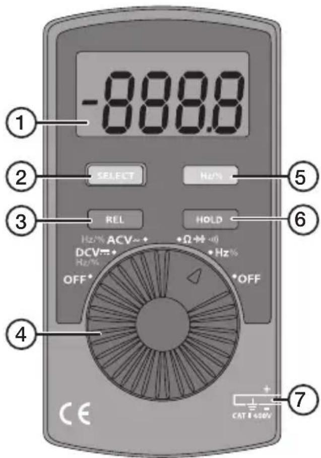
- LCD display
- [SELECT] Press the required number of times to select the required mode: Resistance, diode test or continuity (position only).
- [REL △] Relative measurement, press once to use the current reading as a reference and subtract the previous reading from the current reading*. Press once again to return to normal measurement mode. This function cannot be used for frequency measurement or relative pulse length (Duty Cycle). When relative measurement is selected, the symbol △ will be shown on the display.
- Multifunction selector with five modes.
- [Hz/%] Frequency measurement (Hz) or Duty Cycle value (%)
- [HOLD] Press once to store the current reading, press once to return to normal measurement mode. When hold is selected, the symbol "H" will be shown on the display.
- Test leads: Black (−, negative) Red (+, positive)
* Example: If the stored value is 20.3 V and the present value is 22.0 V, the reading would be 1.7 V if the REL function is activated.
Symbols on the display

The data hold function is activated.

The sleep mode is activated.

Indicates a negative reading.

Indicator for AC measurement.

Indicator for DC measurement.

The Autorange is activated (meter automatically selects the range with best resolution).

The reading is too high for this measuring range.

Indicator for the diode test.

The continuity buzzer is activated.

Low battery warning – replace the battery.

REL is activated, the stored value minus the present value is displayed.


Resistance, Ω (ohm), kΩ (kiloohm), MΩ (megaohm).

V Voltage, mV (millivolt), V (volt).


Frequency, Hz (hertz), kHz (kilohertz).
Operating instructions
Warning!
- Before measuring voltage, always make sure that the meter is set to the correct function range and not set to resistance or diode test mode.
- Use extreme caution when measuring voltages over 60 V, especially when the objects being measured have high power outputs.
- Make sure that the circuit to be tested is not conducting any current before performing resistance measurements or diode tests.
• Always ensure that the correct function and range is selected. - Take extreme care when using the meter on an inductive component such as a transformer, relay coils and the like. High voltage may be induced at the measuring points if an open circuit occurs.
- Make sure that the test leads are in good condition with no damage to the insulation.
• Take care not to exceed the overload limits given in the specifications.
Voltage measurement DC
- Set the multifunction selector to DCV to switch on the multimeter. "DC" and "AUTO" will appear on the display.
- Connect the test leads across the voltage source to be measured. Black lead to the negative (−) and red lead to the positive (+) measuring point.
- Read the value on the display. Note: If the test leads have been connected with the incorrect polarity, a minus (-) will appear before the reading.
- Set the multifunction selector to OFF to switch off the multimeter.

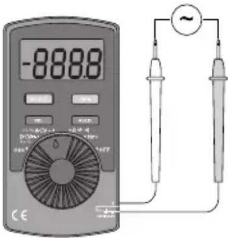
Voltage measurement AC
- Set the multifunction selector to ACV to switch on the multimeter. "AC" and "AUTO" will appear on the display.
- Connect the test leads to the measuring points.
- Read the value on the display.
- Set the multifunction selector to OFF to switch off the multimeter.
Resistance measurement
- Set the multifunction selector to to switch on the multimeter. “M ” appears on the display.
- Connect the test leads to the circuit to be measured.
- Read the value on the display. "OL" will be shown on the display if there is no signal, e.g. if the circuit being measured is open.
- Set the multifunction selector to OFF to switch off the multimeter.
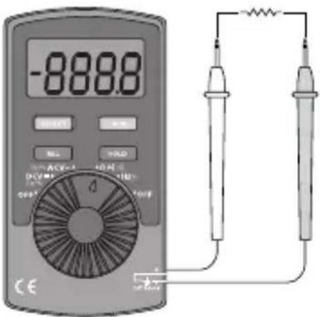
Warning! Ensure that the circuit to be tested is not "live", before taking any measurements.
- The test leads can add 0.1–0.3 Ω to the actual measurement value. To obtain accurate readings of low-resistance components, short-circuit the input terminals to remove the error from the reading on the display.
- For high-resistance measurement (>1 M Ω), it is normal for the reading to take several seconds to stabilize.
Frequency measurement and measurement of relative pulse length (Duty Cycle value)
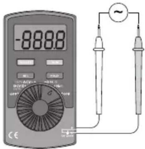
- Set the multifunction selector to Hz % to switch on the multimeter. "Hz" or "%" will be shown on the display.
- Press [Hz %] repeatedly to select frequency measurement (Hz) or relative pulse length (duty cycle) (%).
- Connect the test leads to the circuit to be measured.
- Read the value on the display.
- Set the multifunction selector to OFF to switch off the multimeter.
Warning: Ensure that the circuit to be tested is not "live" before taking any measurements.
Diode test
- Set the multifunction selector to +·s to switch on the multimeter. "MΩ" appears on the display.
- Press [ SELECT ] once to select diode threshold value measurement (V). ⚠️, “OL” and “V” will be shown on the display.
- Connect the black test lead to the cathode and the red test lead to the anode of the diode to be tested. Read the forward voltage drop value from the display. If "1" appears on the display, reverse the polarity of the diode.
- Set the multifunction selector to OFF to switch off the multimeter.
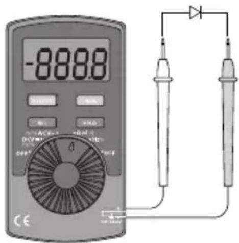
Warning!
Make sure that the circuit to be tested is not conducting any current before testing diodes. Take extreme care when using this instrument on an inductive component such as a transformer, relay coils and the like, and make sure they have been discharged beforehand. High voltage may be induced at the measuring points if an open circuit occurs.
Note: A good diode should have a forward voltage drop of from 0.5 to 0.8 V. However, the reverse voltage drop reading can vary considerably depending on the resistance to other paths of conductance between the tips of the test leads.
Continuity measurement
- Set the multifunction selector to switch on the multimeter. “OL” and “Ω” will be shown on the display.
- Press [SELECT] twice to select continuity measurement.
- Connect the ends of the test leads to the ends of the cables to be tested.
- No break in the lead: The buzzer sounds continuously when the resistance is <60 Ω.
- Break in the lead: The buzzer does not sound.
- Set the multifunction selector to OFF to switch off the multimeter.
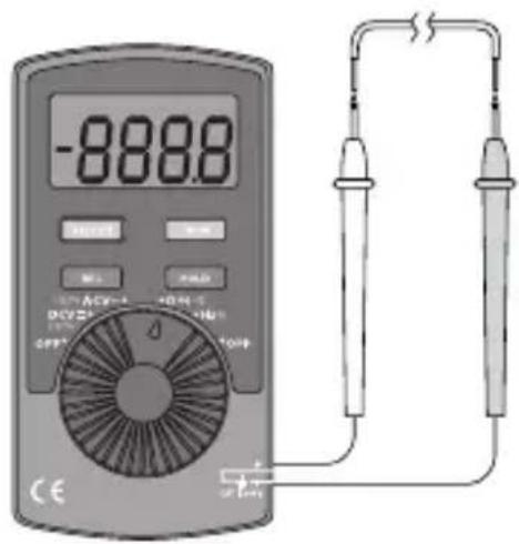
Warning!
Make sure that the circuit to be tested is not conducting any current before testing for continuity.
Take extreme care when using this instrument on an inductive component such as a transformer, relay coils and the like, and make sure they have been discharged beforehand. High voltage may be induced at the measuring points if an open circuit occurs.
To avoid shocks you need to be CAREFUL when you work with voltage higher then 60 VDC or 30 VAC RMS. Voltages higher than this pose a risk of heavy electric shocks.
Note: The open-circuit voltage is around 0.45 V.
Sleep mode (automatic shut-off)
To preserve battery life, the meter has an auto shut-off feature. If the function selector is not turned within 30 minutes, the meter turns itself off automatically. Switch on the multimeter by rotating the function selector or pressing one of the buttons.
Note: The sleep function can be deactivated when the multimeter is switched on by pressing [ SELECT ] for approx. five seconds while at the same time turning the function selector to the required mode. In this mode, the multimeter will not be switched off automatically and measurement can continue for longer than 30 minutes.
Note: Make a habit of switching off the multimeter using the multifunction selector, as it will then be switched off immediately.
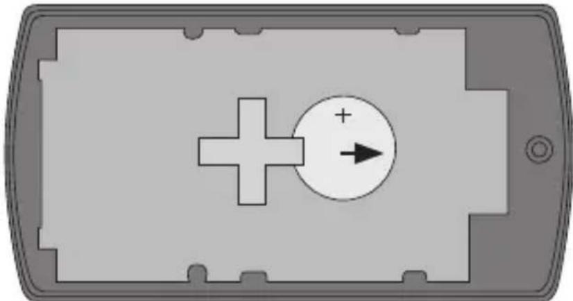
Changing the battery
Change the battery as soon as the battery symbol 📋 appears on the display.
Warning!
Remove the test leads from the circuit being tested before replacing the battery.
natural_image
Diagram of a smartphone casing with a plus sign and circular arrow symbol (no text or labels)- Switch off the multimeter.
- Unscrew the battery cover.
- Push out the old battery to the side and insert the new CR2032 battery (3 V) in the battery compartment with the positive terminal (+) facing upwards.
- Push the battery cover back into position, first on the display side and then the entire battery cover. Tighten the screw.
Care advice
- Switch off the multimeter before cleaning.
- Wipe the meter with a moist, soft cloth. Use a mild detergent and never use solvents or strong, abrasive cleaning agents for cleaning as these can damage the meter.
Disposal
This product should be disposed of in accordance with local regulations. If you are unsure what to do, contact your local authority.
General specifications
Do not measure voltages higher than 600 VDC or 600 VAC RMS using the instrument.
Display LCD display with a maximum value of 3999
Polarity Automatic negative (−) polarity indication
Indication of reading outside
the measuring range Only OL will be shown on the display
Power supply 1 × CR2032 battery (3 V)
Measurement update 3 times per second
Measurement range Automatic mode
Battery warning The battery symbol is shown on the display
Operating environment 0 to +40 °C at humidity ≤ 75 % (up to +30 °C) and ≤ 50 % (over +30 °C)
Storage environment -10 to +50 °C at humidity ≤ 75 % (up to +30 °C) and ≤ 50 % (over +30 °C)
Max. operating altitude Up to 2000 m above sea level
Size (L × W × H) 110 × 58 × 11 mm
Weight (including battery) Approx. 76 g (including test leads and battery)
Accuracy and electrical specifications
| Function Scale Resolution Accuracy (± a % reading, + b number of digits) | Description | |||
| DC 4 V 1 mV | ± (0.8 % +1) | Input impedance | ce | ≥ 10 MΩ |
| 40 V 10 mV | ||||
| 400 V 100 mV | ||||
| 600 V 1 V ± (1 % +3) | ||||
| AC 4 V 1 mV | ± (1.2 % +3) | Input impedance | ce | ≥ 10 MΩResponse: 40–400 Hz;Display: RMS of sine wave(mean value) |
| 40 V 10 mV | ||||
| 400 V 100 mV | ||||
| 600 V 1 V ± (1.5 % +5) | ||||
| Resistance 4 | 00 Ω 0.1 Ω ± (1.2 % +2) The open-circuit voltage isaround 0.45 V. | |||
| 4 kΩ 1 Ω ± (1 % +2) | ||||
| 40 kΩ 10 Ω | ||||
| 400 kΩ | 100 Ω | |||
| 4 MΩ 1 kΩ | ± (1.2 % +2) | |||
| 40 MΩ | 10 kΩ | ± (1.5 % +2) | ||
| Frequency | 99.99 Hz | 0.01 Hz | ± (0.5 % +3) | Input sine wave10 Hz – 10 kHz:≥ 1 V RMS10–100 kHz:≥ 30 V RMS |
| 999.9 Hz | 0.1 Hz | |||
| 9.999 kHz | 0.001 kHz | |||
| 99.99 kHz | 0.01 kHz | |||
| Relative pulse length (Duty Cycle) | 0.1–99.9% | 0.10 % | ||
| Diode | → | 1 mV 0.5–0.8 | V 1.5 V with an open circuit | |
| Continuity | ··· | 0.1 Ω Ca ≤ 60 | Ω ≤ 60 Ω buzzer sounds.> 60 Ω buzzer does not sound. | |
| Battery | < 2.4 V | Battery warning symbol appears. | ||
Multimeter
Art.nr 36-5255 Modell UT120A
Spänningsmätning AC
Resistansmätning
Diodtest
Varning!
natural_image
Diagram of a smartphone casing with a plus sign and circular button, no text or symbols presentIndikator for diodetest.

Summer aktivert for bruddmåling (kontinuitetsmåling).

V Spenning, mV (millivolt), V (volt).


Frekvens, Hz (hertz), kHz (kilohertz).
Bruk
Advarsel!
Diodetest
Advarsel!
natural_image
Diagram of a smartphone casing with a plus sign and circular button, no text or symbols present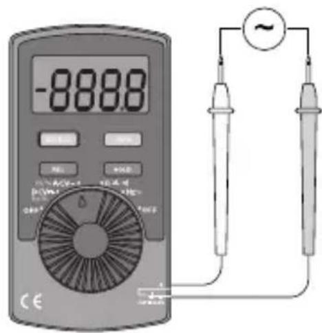
Resistanssimittaus
Dioditestaus
natural_image
Diagram of a smartphone front panel with a plus sign and circular button, no text or symbols present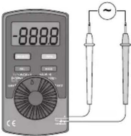
Widerstandsmessung
Diodentest
Warnung:
natural_image
Diagram of a smartphone with a plus sign and circular arrow symbol (no text or labels)Postal 10 – 13 Market Place
Kingston Upon Thames
Surrey
KT1 1JZ
Deutsch
Kundenservice Hotline: 040 2999 78111
E-Mail: kundenservice@clasohlson.de


- Information about the meter
- Categorisation
- Contamination level
- Safety instructions
- Functions
- Symbols on the display
- Operating instructions
- Warning!
- Voltage measurement DC
- Voltage measurement AC
- Resistance measurement
- Frequency measurement and measurement of relative pulse length (Duty Cycle value)
- Diode test
- Continuity measurement
- Sleep mode (automatic shut-off)
- Changing the battery
- Care advice
- Disposal
- General specifications
- Multimeter
- Spänningsmätning AC
- Resistansmätning
- Diodtest
- Varning!
- Bruk
- Advarsel!
- Diodetest
- Resistanssimittaus
- Dioditestaus
- Widerstandsmessung
- Diodentest
- Warnung:
- Deutsch
Brand : Clas Ohlson
Model : UT120A
Category : Multimeter