
720 MX - Pressure washer KARCHER - Free user manual and instructions
Find the device manual for free 720 MX KARCHER in PDF.

User questions about 720 MX KARCHER
0 question about this device. Answer the ones you know or ask your own.
Ask a new question about this device
Download the instructions for your Pressure washer in PDF format for free! Find your manual 720 MX - KARCHER and take your electronic device back in hand. On this page are published all the documents necessary for the use of your device. 720 MX by KARCHER.
USER MANUAL 720 MX KARCHER
natural_image
Icon depicting a person reading a document with an 'i' symbol, no text or numbers present5.961-197 A
12-03-2007978
natural_image
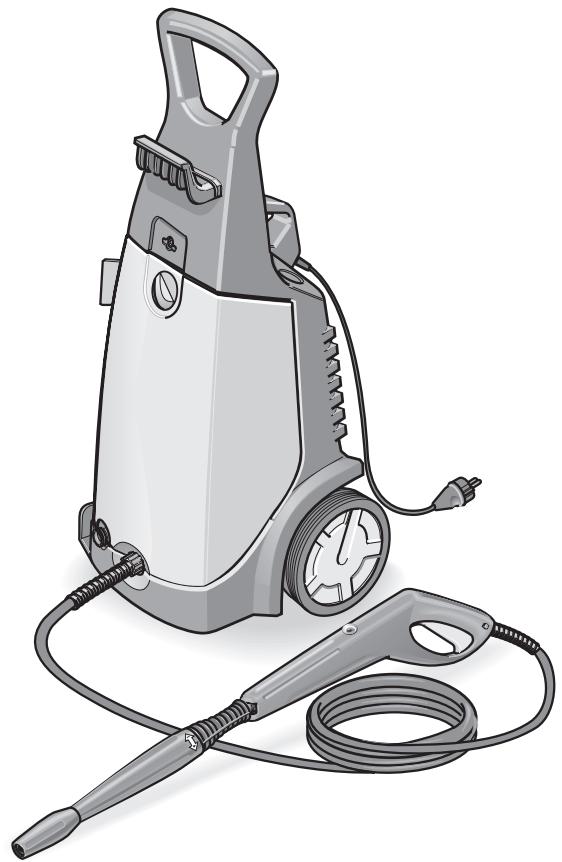
Illustration of a gray pressure cooker with attached hose and power cord (no text or symbols)
K 7.20 MX
720 MX
Deutsch
English
Français
Italiano
Nederlands
Español
Português
English ...... Operating instructions

Caution! Do not use the unit without first having read the operating instructions.

natural_image
Illustration of a hand holding a wrench against a yellow background (no text or symbols)
Montage
Assembly
Assemblage
Montaggio
Montage
Montaje del aparato
Montagem

natural_image
Illustration of a hairbrush cleaning a cable with a mesh cap, set against a yellow background (no text or symbols)
Zubehör
Special accessories
Accessoires en option
Accessori speciali
Speciaal toebehoren
natural_image
Illustration of mechanical gears and a tool on a yellow background (no text or symbols)
Ersatzteile
Replacement parts
Pièces de rechange
Ricambi
natural_image
Illustration of a faucet being inserted into a pipe, showing valve insertion and adjustment (no text or symbols)Wasserversorgung
text_image
Diagram showing a power outlet connected to a plug and its rotary switch, with directional arrows indicating electrical movement.Vorbereiten
text_image
Technical diagram illustrating a medical procedure for using a tool, showing steps 1 and 2 with labeled components.Einschalten
text_image
Diagram showing a rotary switch and its electrical outlet, with directional arrows indicating rotation and power connection.natural_image
Diagram showing a faucet being inserted into a hose with tubing, no text or symbols presentnatural_image
Two-step illustration of a handheld device with arrows indicating motion or force (no text or symbols)text_image
Diagram showing two views of a water heater with temperature and airflow indicators, including a close-up view of the door.natural_image
Cartoon illustration of a smiling arrow-shaped character pushing a car uphill (no text or symbols)natural_image
Illustration of a mechanical assembly with a wrench and pipe, showing tool positioning and component alignment (no text or symbols)Reinigen
natural_image
Illustration of two hands using a tool to adjust or install a pipe fitting, showing mechanical components and a faucet (no text or symbols present)89/336/EWG (+ 91/263/EWG, 92/31/EWG, 93/68/EWG)
2000/14/EG
When unpacking check the contents. Inform your dealer of any damage in transportation.
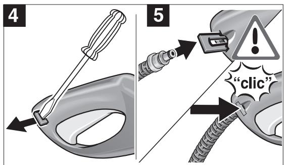
Assembly of the unit is demonstrated with pictures on page 60/61 "Step by Step".
1 Drawing bar
Transport unit over even surfaces
2 Hanger for high-pressure hose
Winding up the high-pressure hose
3 Transport handle
Transport the unit over stairs/obstacles
4 Master switch
Switch on unit - I
Switch off unit - 0
5 Water connection
Connect supply hose
6 High pressure outlet
Connect high-pressure hose
7 Spray lance
Regulate pressure
8 Handgun
Switch on – press safety button and pull lever
Switch off – release lever
9 Power cord with power plug
10 Cleaning agent container
Draw in and meter cleaning agent (+/-)
Safety Notes
Before first use of the unit read these operating instructions and act in accordance with them.
Keep these operating instructions in a safe place for later use or for a subsequent owner.
Use of the unit as authorized
Use this unit exclusively for non-industrial purposes
– for cleaning machines, vehicles, buildings, tools, facades, terraces, garden implements, etc., with high-pressure water jet (if necessary with the addition of cleaning agents).
– for cleaning vehicle engines only in locations equipped with an appropriate oil separator.
– with accessories, replacement parts and cleaning agents authorized by Kärcher. Please comply with instructions supplied with the cleaning agents.
General safety notes
Never permit children and adolescents to handle the unit.
Never leave the unit unattended whilst the master switch is switched on.
Never operate the unit in potentially explosive spaces.
Do not spray any objects which contain health-endangering substances (e.g. asbestos).
Safety Notes
Warning signs on the unit
Never direct the high-pressure jet at human beings, animals, the unit itself or at electrical parts.
Safety devices
Safety devices serve to protect against injuries and must not be changed or circumvented.
Relief valve with pressure switch
When the lever on the handgun is released the pressure switch switches off the pump and the high-pressure jet ceases. When the lever is pulled the pressure switch switches on the pump again.
Moreover, the relief valve prevents the permissible operating pressure from being exceeded.
Safety button
The safety button on the handgun prevents inadvertent switching on of the unit.
Environmental protection
Dispose of packaging
The packaging materials are recyclable. Please hand in the packaging for recycling.
Dispose of old equipment
You can obtain information about environment-protecting disposal from your Kärcher dealer.
Save water
In comparison to other cleaning methods, by the use of this unit you save up to 85 % of the water otherwise needed. The unit can also be operated with rain-water (use a water filter).
Ease the burden on waste water
Please use the cleaning agents sparingly. Observe the dosage recommendations which are supplied with the cleaning agents.
Before first use
Connection requirements
See rating plate or Technical Data for connected values.
Electrical connection
The voltage shown on the rating plate must match the supply voltage. The current source must be properly earthed.
Only use splash-protected extension cable with a sufficient conductor cross-section (10 m: 3 x 1.5 mm ^2 , 30 m: 3 x 2.5 mm ^2 ) and unwind completely from the cable drum.
Connection to water line
Comply with the stipulations of the water supply company.
Supply hose (not supplied).
Only use supply hoses with the following dimensions: length at least 7.5 m, diameter at least 12 ".
Operation
⚠️ Serious danger!
Vehicle tyres and tyre valves can be damaged by the high-pressure jet and become perforated. The first sign of this is a discoloration of the tyre. When cleaning them maintain a distance of at least 30 cm.
Never grasp the power plug with wet hands.
Before each use check the power cord and power plug for damage. Have a damaged power cord replaced immediately by an authorized Kärcher service point or an electrical specialist.
Before each use check the high-pressure hose for damage. Replace a damaged high-pressure hose immediately.
Danger of injury!
Owing to the water jet emerging from the high-pressure nozzle a recoil force operates on the handgun. Ensure you have a secure footing and hold the handgun and spray lance firmly.
If necessary wear protective clothing for protection against return spray.
natural_image
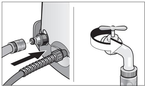
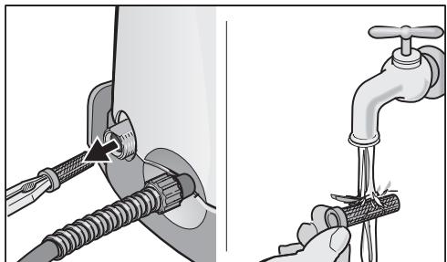
Illustration of a faucet being inserted into a pipe, showing valve insertion and adjustment (no text or symbols)Water supply
The unit can either be supplied from the water main or from water in an open container.
Water supply from the water main
- Connect a supply hose (not included) to the water inlet of the unit and to the water supply (e.g. water tap).
- Open the water supply.
Water supply from an open container
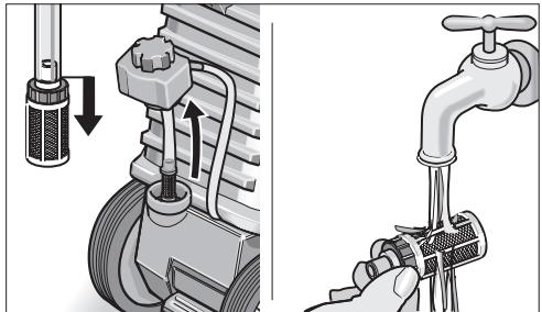
● Unscrew the coupling part for the water inlet.
- Screw the suction hose with filter (not included, see “Special accessories”) onto the water connection of the unit.
● Hang the filter in the container.
- Vent the unit before operation.
- Unscrew the high-pressure line at the high-pressure outlet of the unit.
- Switch on the unit and let it run until water free of bubbles emerges at the high-pressure outlet.
- Switch off the unit and screw on the high-pressure hose again.
Operation
text_image
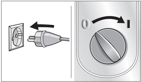
Diagram showing a power outlet connected to a plug and its rotary switch, with directional arrows indicating electrical movement.Preparation
- Insert power plug.
- Turn master switch to "I".
text_image
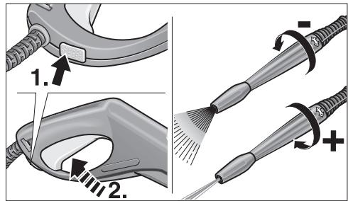
Technical diagram illustrating a medical procedure for using a tool, showing steps 1 and 2 with labeled components.Switching on
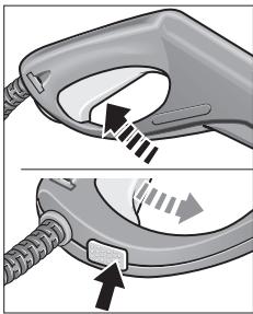
- Press safety button on the handgun and pull the lever.
Switching off
- Release the lever.
During breaks in work and when leaving the unit secure it against inadvertent switching on by pressing the safety button.
Regulate operating pressure/flow rate
Raise operating pressure: twist spray lance in direction “+”.
Reduce operating pressure: twist spray lance in direction “—”.
Connect accessories
Depending on the model the following accessories are either included in the scope of delivery or are obtainable from specialist dealers (see also “Special accessories”).
- Exchange the respective accessory with the spray lance.
Wash brush
for large, smooth surfaces – e.g. on the automobile, caravan or boat.
Cleaning agent can be added.
Rotating wash brush
for gentle and thorough cleaning – e.g. bodywork and glass surfaces.
Cleaning agent can be added.
Rotary nozzle
for stubborn accumulations of grime – e.g. moss-covered promenade tiles or facades.
Work without cleaning agent and with the highest operating pressure.
Operation
text_image
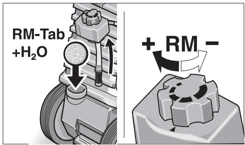
RM-Tab +H₂O + RM -Adding the cleaning agent
- Fill the detergent reservoir with ..... .... Detergent tablet and water or .... Detergent concentrate and water. Observe metering recommendations on the packaging label of the detergent.
- Meter out the cleaning agent (cleaning agent metering valve)
– medium quantity: centre-position
– large quantity: “+” position
– small quantity: “−” position.
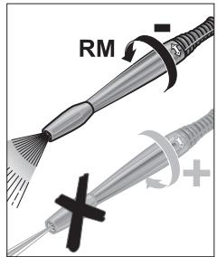
text_image
RM +- Twist the spray lance in the “—” direction until the stop.
Recommended cleaning method
- Spray the cleaning agent on the dry surface sparingly and let it react (but not dry out).
- Wash off the loosened dirt with the high-pressure jet.
Cleaning agents
For trouble-free operation and for matching to the relevant cleaning task we recommend our Kärcher cleaning agents and care range. Please let us advise you or ask for information about them. Here is a small selection:
Universal cleaner Profi RM 555 ULTRA
Automobile cleaner Profi RM 565 ULTRA
House and garden cleaner
Profi RM 570 ULTRA
Boat cleaner Profi RM 575 ULTRA
Finishing operations
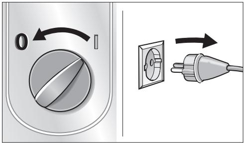
text_image
Diagram showing a rotary switch and its electrical outlet, with directional arrows indicating rotation and power connection.- Master switch to "0".
- Draw out power plug.
natural_image
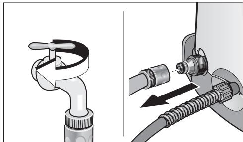
Diagram showing a faucet being inserted into a hose with a valve, illustrating the process (no text or symbols present)When the water has been supplied from the water main
- Close the water supply tap.
- Separate the unit from the water connection.
- Unscrew the suction hose with filter at the water inlet of the unit.
When the water has been supplied from an open container
Finishing operations
natural_image
Two-step illustration of a handheld device with arrows indicating motion or force (no text or symbols)- Pull the lever on the handgun until the unit is without pressure.
- Press in the safety button to protect the unit against inadvertent switching on.
● Wind the high-pressure hose.
Safekeeping / Transportation
text_image
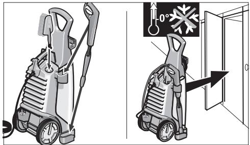
Diagram showing two views of a water heater with temperature and airflow indicators, including a close-up view of the door.Caution! Frost can destroy an incompletely emptied unit. In the winter keep the unit in a frost-free room.
- Separate the spray lance from the handgun and place it in its holder.
natural_image
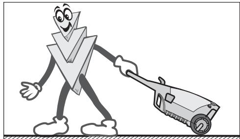
Cartoon illustration of a smiling arrow-shaped character pushing a wheelbarrow (no text or symbols)- Switch off the unit before transporting it.
- To transport it over stairs or obstacles lift the unit at the transportation handle.
- To transport the unit over even surfaces draw it by the drawing bar.
Care and Maintenance
natural_image
Illustration of a mechanical assembly with a wrench and pipe, showing tool positioning and component alignment (no text or symbols)Cleaning
Before long periods of storage, e.g. in winter:
- Pull the cleaning agent metering valve off the cleaning agent suction hose and clean it under running water.
natural_image
Illustration of two hands using a tool to adjust or install a pipe fitting, showing mechanical components and a faucet (no text or symbols present)- Pull out the strainer in the water inlet with flat-nose pliers and clean it under running water.
Maintenance
The unit is maintenance-free.
Help with faults
Faults often have simple causes which you can rectify yourself with the aid of the following summary. In case of doubt or of faults or remedies not mentioned here apply to the authorized customer service.

Danger of electric shock!
Repair work on the unit can only be carried out by the authorized customer service.
Inrush currents cause short-time voltage drops. Under unfavourable power supply conditions other equipment may be affected. If the system impedance of the power supply is < 0,15 Ohms, disturbances are unlikely to occur.
Customer Service
In the case of questions or faults our Kärcher branches will be pleased to assist you further.
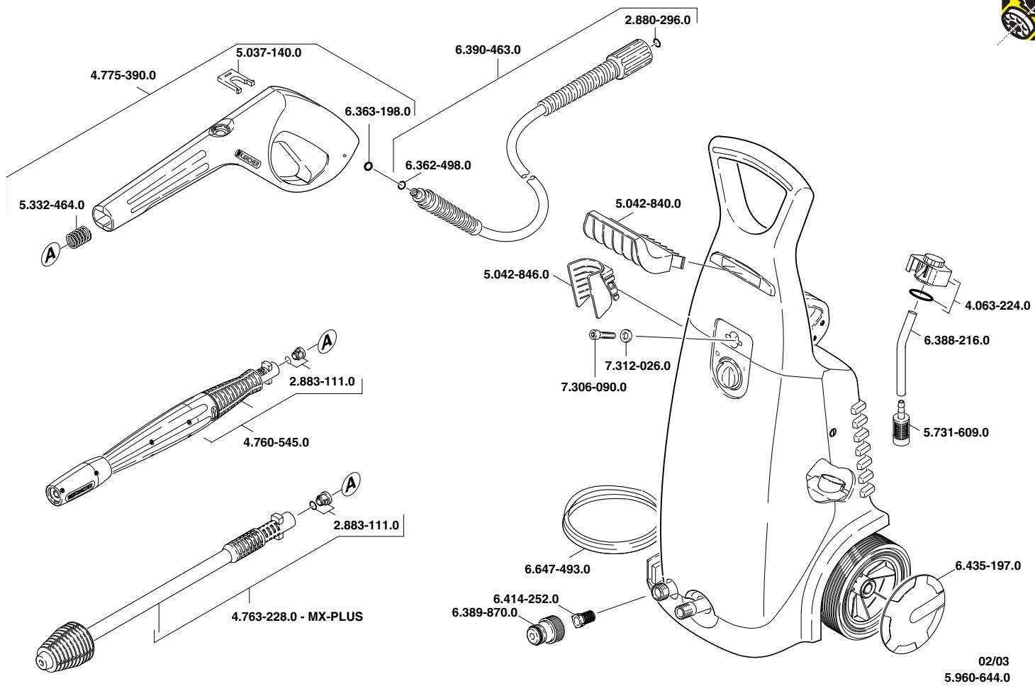
Replacement parts
Use exclusively Kärcher original replacement parts. You will find a replacement parts summary at the end of these operating instructions.
| Fault | Cause | Remedy |
| Unit does not run | Power supply interrupted | Draw out power plug! Check power cord, power plug, extension cable and cable connections for damage |
| Unit does not come up to pressure | Spray lance set to “-” | Set spray lance to “+” |
| In suction operation – unit not vented | Vent unit, see “Operation” | |
| Strainer in water inlet blocked | Clean strainer, see “Care and Maintenance” | |
| Water supply quantity too low | Check the water supply to the water inlet of the unit for leaks and throughput | |
| Strong pressure fluctuations | High-pressure nozzle in spray lance blocked | Take off the spray lance, clean the hole in the high-pressure nozzle with a needle and rinse through with water again |
| Water comes out of the housing underside | Pump leaking | 3 drops per minute are acceptable. For greater leakages contact the customer service |
| Cleaning agent is not drawn in | Spray lance set to “+” | Set spray lance to “-” |
| Cleaning agent valve in the cleaning agent suction hose blocked | Clean cleaning agent metering valve, see “Care and Maintenance” |
Technical Data
Power supply
| Voltage (at 1~50 Hz) | 230 V |
| Connected load | 3,0 kW |
| Supply fuses (time-lag) | 16 A |
| Safety class | 1,IP X5 |
Water connection
| Supply temperature (max.) | 60 ^ |
| Supply volume (min.) | 10 l/min |
| Supply pressure (max.) | (12 bar) 1,2 MPa |
Performance data
| Operating pressure | (140 bar) | 14 MPa |
| Pump pressure max. | (150 bar) | 15 MPa |
| Flow rate | (550 l/h) | 9,2 l/min |
| Cleaning agent metering | 0,6 l/min |
| Suction height from open container (20°C) 1 m | |
| Recoil force of the handgun | 26 N |
| Hand-transmitted vibration (ISO 5349) | 0,8 m/s ^2 |
| Sound pressure level L_PA (EN 60704-1) | 73 dB(A) |
| Sound power level L_WA (2000/14/EC) | 95 dB(A) |
Dimensions
| Length/Width/Height | 340/325/900 mm |
| Weight | 22,5 kg |
Circuit Diagram
C1 Running capacitor
M1 Motor
S1 Pressure operated switch
Q1 Appliance switch with motor protection
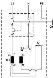
text_image
L1 N PE Q1 U1 M1 U2 Z1 Z2 C1 S1Special accessories
Special accessories expand the scope of use of your machine. You can obtain further information from your Kärcher dealer.
See page 62 for illustrations.
1 Rotary nozzle
2 Spray guard for rotary nozzle
3 Pipe-cleaning set
4 Rotating wash brush
5 Wash brush
6 Wet blasting set
7 Flexible spray lance
8 Three-way nozzle with spray lance
9 Spray lance for places which are difficult to access
10 Floor spray lance
11 Spray lance extension
12 High-pressure hose
13 Hose extension
14 Large volume suction set
15 Suction hose with filter
16 Water filter
17 Non-return valve
18 T-Racer
Guarantee
In each country the guarantee conditions issued by our responsible sales company are applicable. We clear any faults occurring in the unit free of charge during the period of guarantee providing the cause is a fault in a material or in the manufacture.
In the case of a claim under the guarantee please contact your dealer or the nearest authorized customer service point, accompanying your claim with accessories and purchase voucher.
EU Declaration of Conformity
We hereby declare that the equipment described below conforms to the relevant fundamental safety and health requirements of the appropriate EU Directives, both in its basic design and construction as well as in the version marketed by us. This declaration will cease to be valid if any modifications are made to the machine without our express approval.
Product: High-pressure cleaner
Model: 1.034-xxx
Relevant EU Directives:
98/37/EC
73/23/EEC (+ 93/68/EEC)
89/336/EEC (+ 91/263/EEC, 92/31/EEC, 93/68/EEC)
2000/14/EC
Harmonised standards applied:
DIN EN 55014 - 1: 2000 + A1: 2001
DIN EN 55014 - 2: 1997
DIN EN 60335 - 1
DIN EN 60335-2-79
Conformity assessment procedure followed:
Annex V
Sound power level
Measured: 93 dB(A)
Guaranteed: 95 dB(A)
Appropriate internal measures have been taken to ensure that series-production units conform at all times to the requirements of current EU Directives and relevant standards. The signatories are empowered to represent and act on behalf of the company management.
5.957-238 (11/02)
natural_image
Diagram showing two different pipe installation methods: one with a valve inserted into a hose, the other with a faucet handle (no text or symbols present)Alimentation en eau
text_image
Diagram showing a power outlet connected to an electrical switch with directional arrows indicating rotation or adjustment.Préparatifs
text_image
Technical diagram illustrating a medical procedure for using a tool, showing steps 1 and 2 with labeled components.Enclenchement
text_image
Diagram showing a rotary switch with 0° rotation and an electrical socket connected to a plug, illustrating electrical switch behavior.natural_image
Diagram showing a faucet being inserted into a hose with tubing, no text or symbols presentnatural_image
Two-step illustration of a handheld device with arrows indicating motion or force (no text or symbols)text_image
Diagram showing two views of a water heater with temperature and airflow indicators, including a close-up view of the door.natural_image
Cartoon illustration of a smiling character pushing a car uphill (no text or symbols)natural_image
Illustration of a mechanical assembly with a wrench and pipe, showing tool positioning and component alignment (no text or symbols)Nettoyage
natural_image
Illustration of two hands using a tool to adjust a pipe fitting, showing the correct and incorrect states (no text or symbols present)89/336/CEE (+ 91/263/CEE, 92/31/CEE, 93/68/CEE)
2000/14/CE
natural_image
Illustration of a faucet being inserted into a pipe, showing valve insertion and piping connection (no text or symbols)text_image
Diagram showing a power outlet connected to an electrical switch with directional arrows indicating rotation or adjustment.Preparazione
text_image
Technical diagram illustrating a medical procedure for needle insertion, showing steps 1 and 2 with labeled arrows and directional indicators.Inserire
text_image
Diagram showing a rotary switch and an electrical socket with directional arrows indicating rotation or movement.natural_image
Diagram showing a faucet being inserted into a hose, with arrows indicating the insertion direction (no text or symbols present)natural_image
Two-step illustration of a handheld device with arrows indicating motion or force (no text or symbols)text_image
Diagram showing two views of a water heater with temperature and airflow indicators, including a close-up view of the door.natural_image
Cartoon illustration of a smiling V-shaped character pushing a toy car on a flat surface (no text or symbols)natural_image
Illustration of a mechanical assembly with a wrench and pipe, showing tool positioning and component alignment (no text or symbols)Pulizia
natural_image
Illustration of two hands using a tool to adjust or install a pipe fitting, with no visible text or symbols.89/336/CEE (+ 91/263/CEE, 92/31/CEE, 93/68/CEE)
2000/14/CE
natural_image
Illustration of a faucet being inserted into a pipe, showing valve insertion and piping connection (no text or symbols)Watertoevoer
text_image
Diagram showing electrical outlet connection and rotary switch mechanism with directional arrowsVoorbereiden
text_image
Technical diagram illustrating a medical procedure for needle insertion, showing steps 1 and 2 with labeled arrows and directional indicators.Inschakelen
text_image
Diagram showing a rotary switch and its electrical outlet, with directional arrows indicating rotation and power connection.natural_image
Diagram showing a faucet being inserted into a hose with a valve, illustrating the process (no text or symbols present)natural_image
Two-step illustration of a handheld device with arrows indicating motion or force (no text or symbols)text_image
Diagram showing two views of a water heater with temperature and airflow indicators, including a close-up view of the door.natural_image
Cartoon illustration of a smiling arrow-shaped character pushing a car uphill (no text or symbols)natural_image
Illustration of a mechanical assembly with a wrench and pipe, showing tool positioning and component alignment (no text or symbols)Reinigen
natural_image
Illustration of two hands using a tool to adjust or install a pipe fitting, showing mechanical components and a faucet (no text or symbols present)natural_image
Diagram showing two different pipe installation methods: one with a valve inserted into a hose, the other with a faucet handle (no text or symbols present)text_image
Diagram showing electrical outlet connection and rotary switch mechanism with directional arrowsPreparativos
text_image
Technical diagram illustrating a medical procedure for using a tool, showing steps 1 and 2 with labeled components.Conectar el aparato
text_image
Diagram showing a rotary switch and an electrical socket with directional arrows indicating rotation or movement.natural_image
Diagram showing a faucet being inserted into a hose with a valve, illustrating mechanical assembly (no text or symbols present)natural_image
Two-step illustration of a handheld device with arrows indicating motion or force (no text or symbols)text_image
Diagram showing two views of a water heater with temperature and airflow indicators, including a close-up view of the door.natural_image
Cartoon illustration of a smiling arrow-shaped character pushing a car uphill (no text or symbols)natural_image
Illustration of a mechanical assembly with a screwdriver and pipe fitting, showing tool positioning and component alignment (no text or symbols)natural_image
Illustration of two hands using a tool to adjust or install a pipe fitting (no text or symbols present)89/336/CEE (+ 91/263/CEE, 92/31/CEE, 93/68/CEE)
2000/14/CE
natural_image
Illustration of a faucet being inserted into a pipe, showing valve insertion and piping connection (no text or symbols)text_image
Diagram showing a power outlet connected to a plug and its rotary switch, with directional arrows indicating electrical movement.Preparar
text_image
Technical diagram illustrating a medical procedure for using a tool, showing steps 1 and 2 with labeled components.Ligar
text_image
Diagram showing a rotary switch and its electrical outlet, with directional arrows indicating rotation and power connection.natural_image
Diagram showing a faucet being inserted into a hose with a valve, illustrating the process (no text or symbols present)natural_image
Two-step illustration of a handheld device with arrows indicating motion or force (no text or symbols)text_image
Diagram showing two views of a water heater with temperature and airflow indicators, including a close-up view of the door.natural_image
Cartoon illustration of a smiling arrow-shaped character pushing a toy car uphill (no text or symbols)natural_image
Illustration of a mechanical assembly with a wrench and pipe, showing tool positioning and component alignment (no text or symbols)Limpar
natural_image
Illustration of two hands using a tool to adjust a pipe fitting (no text or symbols present)89/336/CEE (+ 91/263/CEE, 92/31/CEE, 93/68/CEE)
2000/14/CE
natural_image
Illustration of various cleaning and maintenance tools including a power tool, hose, and pressure cooker (no text or labels)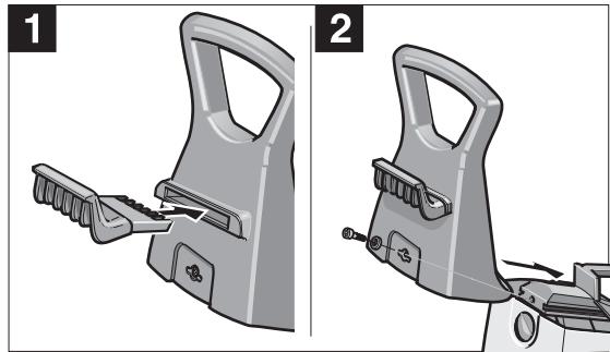
natural_image
Two-step diagram showing a hair cleaner's side profile and its internal mechanism, with no visible text or symbols.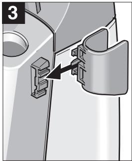
natural_image
Mechanical component diagram showing a bracket with an arrow pointing to a detail (no text or symbols present)
text_image
4 5 "clic"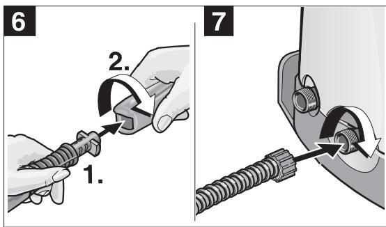
text_image
6 1. 2. 7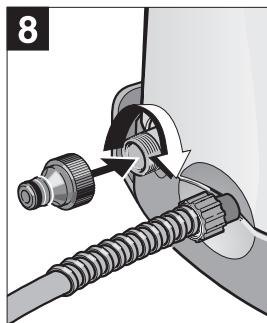
natural_image
Mechanical assembly diagram showing a pipe fitting with a valve and connecting rod (no text or symbols)1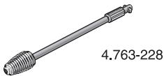 | 62.1 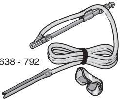 | 11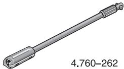 | 15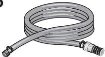 4.440 - 238 4.440 - 238 | |
2 | 7265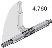 | 12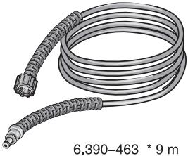 | 16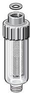 4.730-059 4.730-059 | |
3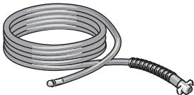 2.637 - 729 * 7,5 m2.637 - 767 * 15 m 2.637 - 729 * 7,5 m2.637 - 767 * 15 m | 8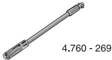 | 17[cxky]6.412 - 578 | ||
4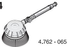 | 9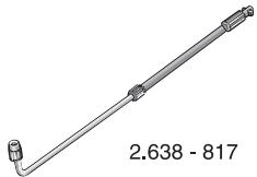 | 13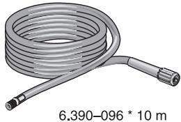 | 18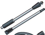 2.640-157(SK)2.640-212(EU)2.640-213(CE) 2.640-157(SK)2.640-212(EU)2.640-213(CE) | |
5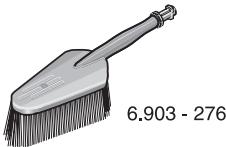 | 10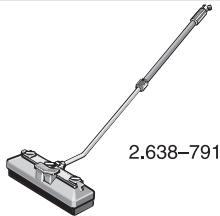 | 14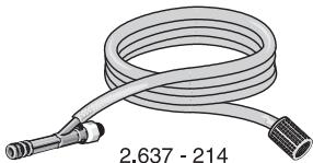 | ||
text_image
4.775-390.0 5.037-140.0 6.363-198.0 6.362-498.0 2.880-296.0 5.332-464.0 5.042-840.0 5.042-846.0 7.312-026.0 7.306-090.0 4.063-224.0 6.388-216.0 5.731-609.0 4.760-545.0 2.883-111.0 2.883-111.0 4.763-228.0 - MX-PLUS 6.647-493.0 6.414-252.0 6.389-870.0 6.435-197.0 02/03 5.960-644.0A
Alfred Kärcher Ges.m.b.H.
Lichtblaustraße 7
1220 Wien
(01) 25 06 00
AUS
Kärcher Pty Ltd
40 Koornang Road
Scoresby Vic 3179
Victoria, Australia
(03) 9765 - 2300
DK
Kärcher Rengøringssystemer A/S
Gejlhavegård 5
6000 Kolding
70 20 66 67
E
Kärcher S.A.
Pol. Industrial Font del Radium
Dr. Trueta, 6-7
08400 Granollers (Barcelona)
(93) 846 44 47
GR
Kärcher Cleaning Systems A.E.
31-33, Nikitara str. &
Konstantinoupoleos str.
136 71 Acharnes
210-23 16 153
H
6975 Creditview Road, Unit 2
Mississauga, Ontario L5N 8E9
(905) 672 98 23
CH
Kärcher AG
Industriestraße 16
8108 Dällikon
0844 850 863
CZ
Kärcher spol.s.r.o.
Za Mototechnou 1114/4
155 00 Praha 5 -Stodûlky
0235 521 665
D
natural_image
World map with connecting lines radiating from a central point, no text or symbols presentF
Kärcher S.A.
Banbury, Oxon, OX16 1TB
01295/752000; 09066/800632
HK
Kärcher Ltd.
Unit 10, 17/F., APEC Plaza
49 Hoi Yuen Road,
Kwun Tong, Kowloon
2357 5863
|
Kärcher S.p.A.
Via Elvezia 4
21050 Cantello (VA)
03 32 / 848 - 99 88 77
IRL
Karcher Limited
12 Willow Business Park
Nangor Road
Clondalkin Dublin 12
01/4097777
J
Kärcher Co., Ltd.
No.2, Matsusaka-Daira 3-chome
Taiwa-cho, Kurokawa-gun
Miyagi, 981-3408
022/344 3140
MAL
Karcher Cleaning Systems Sdn. Bhd.
8 Jalan Serindit2
Bandar Puchong Jaya
47100 Puchong, Selangor
58821148
MEX
Karcher México, SA de CV
East Tamaki, Auckland
09/274 46 03
P
Neoparts Com. e Ind. Automóvel, Lda.
Kärcher Poland Ltd. Sp. z o.o.
Ul. Stawowa 140
31-346 Kraków
012/6397222
PRC
BKC Equipment Co., Ltd.
No 16, Honda Beilu
Beijing Economic & Technological Area
Beijing 100176
010/67881653
S
Kärcher AB
Tagenevägen 31
42502 Hisings-Kärra
031-577300
SGP
Karcher Asia Pacific Pte Ltd
30 Toh Guan Road Singapore
07-05 ODC Building
Singapore 608840
68971811
TR
Kärcher Servis Ticaret A.S.
9 Eylül Mahallesi
307 Sokak No. 6
Gaziemir / Izmir
0232/2520708
TWN
Karcher Taiwan Limited
5F/6. No.7 Wu-Chuan 1st Rd
Taipei County, Taiwan R.O.C
2 2299 9626
UAE
Karcher FZE
Jebel Ali Free Zone
RA 8, XB 1, Jebel Ali, Dubai
04/8836776
USA
Alfred Karcher, Inc
2170 Satellite Blvd, Suite 350
Duluth, GA 30097
678-935-4545;877-527-2437
ZA
Kärcher (Pty) Ltd.
P.O. Box 11818
Vorna Valley 1686
011/4662434