YT6701 - Lawn mower Cotech - Free user manual and instructions
Find the device manual for free YT6701 Cotech in PDF.


| Product Type | Lawn Mower |
| Model | YT6701 |
| Brand | Cotech |
| Power Source | Electric (corded) |
| Motor Power | 1600 W |
| Cutting Width | 42 cm |
| Cutting Height Adjustment | 6 positions (25-75 mm) |
| Grass Collection Bag Capacity | 50 L |
| Weight | 12.5 kg |
| Dimensions (L x W x H) | 650 x 450 x 350 mm |
| Noise Level | 85 dB(A) |
| Safety Features | Safety switch, blade brake |
| Maintenance | Regular blade sharpening, clean underside |
| Spare Parts Availability | Blades, wheels, collection bag |
| Repairability | DIY-friendly with common tools |
| Warranty | 2 years |
| Manual Languages | EN, DE, FI, NO, SV |
Frequently Asked Questions - YT6701 Cotech
User questions about YT6701 Cotech
0 question about this device. Answer the ones you know or ask your own.
Ask a new question about this device
Download the instructions for your Lawn mower in PDF format for free! Find your manual YT6701 - Cotech and take your electronic device back in hand. On this page are published all the documents necessary for the use of your device. YT6701 by Cotech.
USER MANUAL YT6701 Cotech
Lawn Raker/Scarifier
Mossrivare/vertikalskärare
Read the entire instruction manual carefully and make sure that you fully understand it before you use the equipment. Keep the manual for future reference.
Viktig information:
natural_image
Line drawing of a lawn mower with attached hoses and wheels (no text or symbols)ART.NO
18-4458
31-5275
MODEL
YT6701-UK
YT6701
Ver. 20131203
Original instructions
Bruksanvisning i original
Lawn Raker/Scarifier
ART.NO 18-4458 MODEL YT6701-UK
31-5275 YT6701
Please read the entire instruction manual before use and save it for future reference. We reserve the right for any errors in text or images and for making any necessary technical changes to this document. If you should have any questions concerning technical problems please contact our Customer Services.
Safety

Warning!

Read the instruction manual before operating this machine

CE marking

Double insulation

To avoid electric shock avoid cutting the grass after it has rained. Do not leave the lawnmower outdoors during rain.

The blades will continue to rotate after the motor has been turned off.

Extremely sharp cutting blades. The blades will continue to rotate after the motor has been turned off. Unplug the mains lead before carrying out any maintenance, repairs or service.

Keep bystanders at a safe distance.

Keep the mains lead away from the rotating cutting blade.
General safety instructions
- The lawn raker must not be used by anyone (including children) suffering from physical or mental impairment. This product should not be used by anyone that has not read the instruction manual unless they have been instructed in its use by someone who will take responsibility for their safety.
- Never let children play with the lawn raker.
- The product should only be used as described in the instruction manual.
- Remember that it is the user who is ultimately responsible for any accidents or hazards that cause possible injury to others and to property.
- If the mains lead is damaged it must be replaced by a qualified electrician or Clas Ohlson Customer Services.
- The lawn raker should be connected to a mains outlet protected by a 30 mA RCD.
- Never use the lawn raker when you are tired, sick, under the influence of alcohol or medicine.
Pre-work safety precautions
- Read the entire instruction manual carefully.
- Never let children or others use the lawn raker without having read the instruction manual. Check for any local regulations that may stipulate a minimum operating age.
- Never use the lawn raker in the presence of bystanders, especially children or animals.
- Always use appropriately designed footwear and long trousers. Never use the lawn raker while barefoot or wearing open-toed sandals.
- Never wear loose-fitting clothing or clothes which have any loose hanging straps, bands, etc.
- Always inspect the area to be scarified before starting work. Remove any objects from the area to be scarified that can be thrown by the lawn raker.
- Make sure that the lawn raker is completely assembled and that all parts are whole and functioning normally before commencing work.
- Check that all cables are whole and undamaged. Also check the lawn raker's fixed motor cable.
- Never use the lawn raker if any of its cables or connections is damaged.
- Make sure that all screws and bolts are properly tightened and that all safety devices are in place before commencing work.
Operating safety precautions
- The lawn raker is not designed for professional use or to be used for hire. The product is only intended for domestic use.
- Only use extension leads approved for outdoor use.
- Only use the lawn raker during daylight hours or under good lighting conditions.
- The lawn raker should only be connected to a 230–240 V, 50 Hz mains outlet protected by a 30 mA RCD.
- Avoid scarifying wet grass.
• Always cut at an easy pace. Do not hurry. - Be extra careful when scarifying on slopes.
• Always scarify across slopes. Never up and down.
• Always be extra careful when changing directions on a slope. - Never scarify on steep slopes.
• Always be extra careful when backing or pulling the lawn raker towards yourself. - Always turn off the lawn raker and pull the plug from the mains whenever crossing other surfaces, such as gravel, asphalt, etc.
- Never use the lawn raker if any part of the body has been damaged. Never use the lawn raker without having the collector attached.
- Make sure that the lawn raker stands steady on all four wheels before starting. Keep hands and feet away from the rotating blades at all times.
- Turn off the lawn raker and pull out the plug from the wall socket, whenever taking a pause from work.
- Turn off the lawn raker and pull out the plug from the wall socket, whenever emptying the collector, cleaning or carrying out any other type of maintenance.
- Turn off the lawn raker and pull out the plug from the wall socket, whenever the blades strike any unidentified object. Check the lawn raker's blades and rake tines. Repair any eventual damage before restarting the lawn raker.
- If any abnormal vibration or noise is detected, turn off the lawn raker and unplug it immediately. Check the blades and rake tines, tighten any loose screws and repair any damage before re-commencing work.
- Always be aware of the location and position of the mains lead while scarifying. Make sure that the mains lead does not come into contact with the lawn raker or its rotating blades.
Product description

- Collector
- Discharge cover
- Bottom handle chassis connection
- Motor cover
- Height adjustment lever

- Start lever
- Safety cut-off
- Strain-relief
- Motor cable
- Upper handle adjustments

natural_image
Mechanical linkage diagram showing a curved bracket with six circular components attached (no text or symbols)- Cable clips
- Upper handle
- Retaining nut and bolt for upper and lower handle
- Cable clips
- Bottom handle
Assembly
Handle assembly

natural_image
Mechanical component diagram showing a lever and shaft assembly (no text or symbols)- Connect the lower handle to the lawn raker's chassis connection and secure it with the lock knobs.

natural_image
Mechanical assembly diagram showing a wheel fastener and bracket (no text or symbols)-
Align the upper handle's bolt holes over the lower handle and secure them with the supplied bolts and knobs.
-
Secure the motor cable to the handle using the supplied cable clips.
Collector
- Hold the collector near the discharge chute and open the discharge cover.

natural_image
Mechanical assembly diagram showing a vehicle with attached components and wiring (no text or symbols)- Hook the collector's retaining pins into the lawn raker's retaining notches.

natural_image
Illustration of a garment pattern with measurement lines and connectors (no text or symbols)
natural_image
Cross-sectional diagram of a mechanical assembly (no visible text or labels)
natural_image
Mechanical assembly diagram showing a vehicle chassis with mounting brackets and structural components (no text or symbols)Operating instructions
Connecting the mains lead
Note: Only use an extension lead approved for outdoor use.
- Connect the extension lead to the lawn raker's mains lead socket and run the lead through the handle's strain-relief.

- The extension lead should only be connected to a 230–240 V, 50 Hz mains outlet protected by a 30 mA RCD.
Starting
Note: Make sure that the lawn raker does not contact the lawn and possibly pull away when starting. Place the lawn raker to its highest height setting to ensure a generous free ground clearance and always start on low-grass area that can be easily worked. Thereafter, adjust the working height to the appropriate setting.

natural_image
Diagram of a mechanical component with a knob inserted, showing internal structure and a handle (no text or symbols)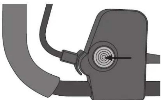
natural_image
Mechanical component diagram showing a curved pipe joint with a circular target and arrow indicator (no text or symbols)
natural_image
Mechanical component diagram showing a curved arm and connector (no text or symbols)- Press and hold down the safety cut-off button. 2. Clasp the start lever (8) without releasing
the safety cut-off button, when starting. - Release the safety cut-off while clasping the start lever with both hands.
Stopping
Turn off the lawn raker by releasing the start lever.
Working height
The working height is adjusted by manoeuvring the height adjustment lever to the desired position.
4 settings are available:
- 5 mm: 5 mm above normal setting
• 0: Normal setting
-5 mm: 5 mm below normal setting
-10 mm: 10 mm below normal setting
Adjusting the upper handle position
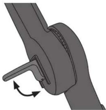
- Open the handle's lock levers on both sides.
- Adjust the handle to the desired position.
- Close the lock levers to lock.
natural_image
Mechanical component diagram showing a lever and curved arm with rotational motion arrows (no text or symbols)Scarifying
• Make sure that the extension lead always trails behind or lies on an area that has already been scarified.
- Be extra careful not to damage the extension lead or pinch it while working.
- Scarify with a slight overlap to achieve the best results.
Protecting the extension lead while scarifying:

flowchart
graph TD
    A["1"] --> B["2"]
    B --> C["3"]
    C --> D["4"]
    D --> E["5"]
    E --> F["6"]
    F --> G["7"]
    G --> H["8"]
    H --> I["9"]
    I --> J["10"]
    style A fill:#f9f,stroke:#333
    style B fill:#f9f,stroke:#333
    style C fill:#f9f,stroke:#333
    style D fill:#f9f,stroke:#333
    style E fill:#f9f,stroke:#333
    style F fill:#f9f,stroke:#333
    style G fill:#f9f,stroke:#333
    style H fill:#f9f,stroke:#333
    style I fill:#f9f,stroke:#333
    style J fill:#f9f,stroke:#333
Emptying the collector
- Turn off the lawn rake and pull the plug from the wall socket.
- Lift the discharge cover and detach the collector.
- Empty the grass and clean the discharge chute from any excessive grass and debris.
Use a proper tool for cleaning the chute. Never use your hands or feet. - Lift the discharge cover and reattach the collector.
Storage and maintenance
Note: Turn off the lawn raker, pull out the plug and let it cool before carrying out any service or maintenance.
Care and maintenance
- Clean the lawn raker's exterior using a lightly moistened cloth. Only use mild cleaning agents, never solvents or corrosive chemicals.
• Make sure that the ventilation ports on the motor cover are clean and free from contaminants.

natural_image
Technical line drawing of a mechanical component with ventilation slots and a directional arrow (no text or symbols)
natural_image
Technical line drawing of a vehicle's front and side views showing engine, dashboard, and wheel (no text or symbols)- Inspect the lawn raker regularly to make sure that all bolts and nuts are securely tightened and that there is no visible damage.
- Regular checks should be made to ensure that the lawn raker is always in good running condition.
• Repairs must only be carried out by qualified service technicians and only using genuine spare parts. - Always keep the blade, rake tines and blade housing free and clear of grass and debris to ensure optimal performance.
- Regularly check the lawn raker's blades and rake tines. Make sure they are undamaged and in good condition.
Storage
- Make sure the lawn raker is off, pull out the plug and let it cool before storing.
- Clean the lawn raker thoroughly and check for any signs of visible damage.
- Check that all screws, bolts, nuts, etc are securely tightened.
- Store the lawn raker in a dry, sheltered place out of the reach of children.
Troubleshooting guide
| The lawn raker does not start. | The extension lead is not connected correctly.Check that the wall socket is live.Unplug the lawn rake and make sure that the blade and rake tines rotate freely and are not hindered by grass and debris in the blade housing or discharge chute. |
| The motor loses power. Check for adequate working height. If the lawn raker is set too low the motor may struggle and lose power.Unplug the lawn rake and make sure that the blade and rake tines rotate freely and are not hindered by grass and debris in the blade housing or discharge chute. | |
| Abnormal vibrations occur. Check the lawn raker's blades and rake tines. Replace parts or repair if needed.Unplug the lawn rake and make sure that the blade and rake tines rotate freely and are not hindered by grass and debris in the blade housing or discharge chute. | |

Disposal
This product should be disposed of in accordance with local regulations.
If you are unsure how to proceed, contact your local authority.
Specifications
Rated voltage 230–240 V, 50 Hz
Power 1,800 W
Speed 3,600 rpm
Working width 360 mm
Weight 14 kg
Noise level LpA: 86,9 dB(A) (KpA: 3 dB)
LwA: 102 dB(A) (KwA: 3 dB)
Vibration value 3.944 m/s² (K: 1.5 m/s²)
Mossrivare/vertikalskärare
ART.NR 18-4458 MODELL YT6701-UK 31-5275 YT6701
natural_image
Mechanical linkage diagram showing a bracket with attached components and five circular fasteners (no text or symbols)natural_image
Mechanical component diagram showing a lever and shaft assembly (no text or symbols)natural_image
Cross-sectional diagram of a mechanical assembly (no visible text or labels)
natural_image
Mechanical assembly diagram showing a wheel fastener and bracket (no text or symbols)natural_image
Mechanical assembly diagram showing a vehicle with attached components and a lever mechanism (no text or symbols)
natural_image
Illustration of a garment pattern with measurement tools (no text or symbols)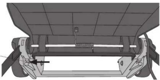
natural_image
Mechanical assembly diagram showing a vehicle chassis with mounting brackets and a central shaft (no text or symbols)Användning
natural_image
Mechanical component with attached wiring and mounting bracket (no text or symbols visible)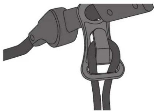
natural_image
Illustration of a mechanical clamp or bracket with no visible text or symbolsnatural_image
Mechanical component diagram showing a lever interacting with a slot (no text or symbols)
natural_image
Mechanical component diagram showing a curved pipe joint with a circular target and arrow indicator (no text or symbols)
natural_image
Mechanical component diagram showing a curved arm and connector (no text or symbols)natural_image
Mechanical diagram showing a lever mechanism with rotational motion arrows (no text or symbols)Mossrivning
natural_image
Technical illustration of a mechanical component with ventilation slots and a directional arrow (no text or symbols)
natural_image
Side profile diagram of a vehicle's front and rear engine compartment, showing structural components and airflow direction (no text or symbols)natural_image
Mechanical linkage diagram showing a bracket with attached components and five circular fasteners (no text or symbols)natural_image
Mechanical component diagram showing a lever and shaft assembly (no text or symbols)- Fest håndtakets underdel til moseriveren og lås med låsemutteren.

natural_image
Mechanical assembly diagram showing a wheel fastener and bracket (no text or symbols)natural_image
Mechanical assembly diagram showing internal components and motion direction (no text or labels)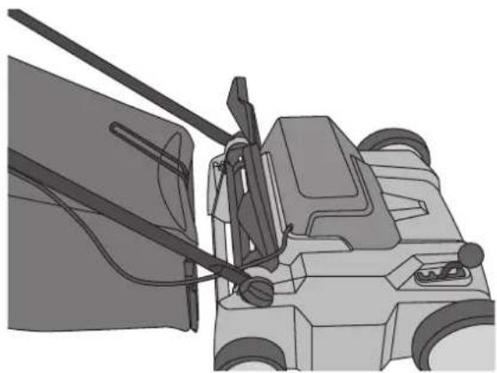
natural_image
Mechanical assembly diagram showing a vehicle with attached components and wiring (no text or symbols)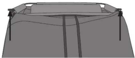
natural_image
Illustration of a garment pattern piece with measurement arrows indicating measurement points (no text or symbols)
natural_image
Mechanical assembly diagram showing a vehicle chassis with mounting brackets and a central shaft (no text or symbols)Bruk
natural_image
Technical illustration of two types of electric vehicle plug connectors (no text or symbols)- Produktet skal kun kobles til strømuttak med 230–240 V, 50 Hz, som er sikret med jordfeilsbryter (RCD) på 30 mA.
Start
natural_image
Diagram of a mechanical component with a knob inserted, showing internal structure (no text or symbols)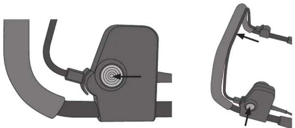
natural_image
Technical illustration of a mechanical component with two views (top and side), showing internal parts and arrows indicating motion or assembly (no text or symbols present)natural_image
Mechanical component diagram showing a curved joint with rotational arrow indicating motion (no text or symbols)Moseriving
natural_image
Simple line drawing of a car on a curved path with a cross mark, no text or symbols presentnatural_image
Technical illustration of a device casing with ventilation slots and a highlighted component (no text or symbols)
natural_image
Side profile diagram of a vehicle's front and rear engine compartment showing structural components (no text or symbols)natural_image
Mechanical linkage diagram showing a bracket with attached components and five circular fasteners (no text or symbols)natural_image
Mechanical component diagram showing a lever and shaft assembly (no text or symbols)natural_image
Mechanical assembly diagram showing a wheel fastener and bracket (no text or symbols)natural_image
Mechanical assembly diagram showing a vehicle with attached components and wiring (no text or symbols visible)natural_image
Illustration of a garment pattern with measurement lines and connectors (no text or symbols)
natural_image
Cross-sectional diagram of a mechanical assembly (no visible text or labels)
natural_image
Mechanical assembly diagram showing a vehicle chassis with mounting brackets and a central shaft (no text or symbols)Käyttö
natural_image
Technical illustration of two types of electrical plug connectors (no text or symbols)natural_image
Diagram of a mechanical component with a handle and internal slot (no text or symbols)
natural_image
Technical illustration of a mechanical device with two views showing internal components (no text or symbols)natural_image
Mechanical component diagram showing a lever and curved arm with rotational arrow (no text or symbols)Sammaleenpoisto
natural_image
Simple line drawing of a car on a curved path with a cross symbol (no text or labels)natural_image
Technical illustration of a mechanical component with a highlighted section and directional arrow (no text or symbols)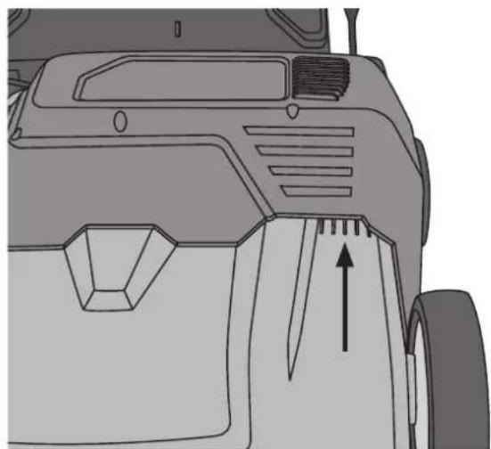
natural_image
Side view of a vehicle's rear dashboard and steering wheel (no text or symbols visible)natural_image
Mechanical linkage diagram showing a bracket with attached components and five hanging circular weights (no text or symbols)natural_image
Mechanical component diagram showing a lever and shaft assembly (no text or symbols)natural_image
Mechanical assembly diagram showing a wheel fastener and bracket (no text or symbols)natural_image
Mechanical assembly diagram showing a vehicle with attached components and wiring (no text or symbols visible)natural_image
Illustration of a garment pattern with measurement pins and stitching (no text or symbols)
natural_image
Mechanical assembly diagram showing internal components and motion direction (no text or labels)
natural_image
Mechanical assembly diagram showing a vehicle chassis with mounting brackets and a central shaft (no text or symbols)Anwendung
natural_image
3D rendering of a mechanical clamp or connector assembly with no visible text or symbols
natural_image
Illustration of a mechanical clamp or clamping device with no visible text or symbolsnatural_image
Mechanical component diagram showing a lever interacting with a slot (no text or symbols)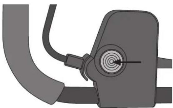
natural_image
Mechanical component diagram showing a curved pipe joint with a circular target and arrow indicator (no text or symbols)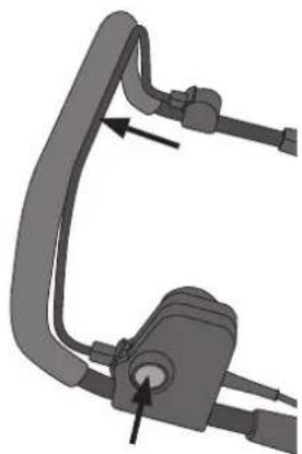
natural_image
Mechanical component diagram showing a curved arm and connector (no text or symbols)natural_image
Mechanical diagram showing a lever mechanism with rotational motion arrows (no text or symbols)Den Rasen lüften
natural_image
Technical illustration of a mechanical component with a highlighted section and directional arrow (no text or symbols)
natural_image
Side profile diagram of a vehicle's front and rear dashboard showing structural components (no text or symbols)Declaration of Conformity
POSTAL 10 – 13 Market Place
Kingston Upon Thames
Surrey
KT1 1|Z
DEUTSCHLAND


- Lawn Raker/Scarifier
- Safety
- General safety instructions
- Pre-work safety precautions
- Operating safety precautions
- Product description
- Assembly
- Handle assembly
- Collector
- Operating instructions
- Connecting the mains lead
- Starting
- Stopping
- Working height
- Adjusting the upper handle position
- Scarifying
- Emptying the collector
- Storage and maintenance
- Care and maintenance
- Storage
- Troubleshooting guide
- Disposal
- Specifications
- Mossrivare/vertikalskärare
- Användning
- Mossrivning
- Bruk
- Start
- Moseriving
- Käyttö
- Sammaleenpoisto
- Anwendung
- Den Rasen lüften
- Declaration of Conformity
- DEUTSCHLAND
Brand : Cotech
Model : YT6701
Category : Lawn mower