
DV16VSS - Drill HiKOKI - Free user manual and instructions
Find the device manual for free DV16VSS HiKOKI in PDF.


| Product Type | Corded Drill |
| Model | DV16VSS |
| Brand | HiKOKI |
| Power Input | 1050 W |
| No-Load Speed | 0 – 1200 rpm (variable) |
| Chuck Type | Keyless, 16 mm (1/2 in) |
| Drilling Capacity (Steel) | 16 mm |
| Drilling Capacity (Wood) | 40 mm |
| Drilling Capacity (Masonry) | 20 mm (hammer mode) |
| Hammer Action | Yes, selectable |
| Reverse Rotation | Yes |
| Variable Speed Trigger | Yes, with lock button |
| Depth Gauge | Adjustable steel rod |
| Side Handle | Include |
| Weight | 2.1 kg |
| Dimensions (L x H) | 380 x 230 mm |
| Power Cord Length | 2.5 m |
| Insulation Class | Double insulated (Class II) |
| Carbon Brushes | Replaceable |
| Maintenance | Clean vents, lubricate gears annually |
| Safety Features | Lock-off switch, thermal protection |
| Package Contents | Drill, side handle, depth gauge, chuck key, case |
Frequently Asked Questions - DV16VSS HiKOKI
User questions about DV16VSS HiKOKI
0 question about this device. Answer the ones you know or ask your own.
Ask a new question about this device
Download the instructions for your Drill in PDF format for free! Find your manual DV16VSS - HiKOKI and take your electronic device back in hand. On this page are published all the documents necessary for the use of your device. DV16VSS by HiKOKI.
USER MANUAL DV16VSS HiKOKI
natural_image
Line drawing of a drill bit with threaded shaft and handle (no text or symbols)Read through carefully and understand these instructions before use. Diese Anleitung vor Benutzung des Werkzeugs sorgfältig durchlesen und verstehen. Диаβάστε προσεκτικά και κατανοήσετε αυτές τις οδηγίες πριν τη χρήση. Przed użytkowaniem należy dokładnie przeczytać niniejszą instrukcję i zrozumieć jej treść. Használat elött olvassa el figyelmesen a használati utasítást. Před použitím si pečlivě přečtěte tento návod a ujistěte se, že mu dobre rozumíte. Aleti kullanmadan önce bu kılavuzu iyice okuyun ve talimatları anlayın. Înainte de utilizare, citiți cu atenție și întelegeți prezentele instrucțiuni. Pred uporabo natančno preberite in razumite ta navodila. Pred použitím si dôkladne tieto pokyny prečítajte a pochopte ich. Будь ласка, прочитайте інструкції і перевірте себе, чи все зрозуміло, перш ніж користуватися приладом. Пайдалану алдында осы нүсқауларды мұқият оқып шығыңыз және түсініңіз. Внимательно прочтите данную инструкцию по эксплуатации, прежде чем пользоваться инструментом.

Handling instructions Bedienungsanleitung Οδηγίες χειρισμού Instrukcja obsługi Kezelési utasítás Návod k obsluze Kullanım talimatları
2
3
4
5
6
7
natural_image
Diagram of a device interior with a central control panel and numbered label (15), no readable text or symbols present.8
9
natural_image
Diagram of a drill bit milling operation with no text or symbols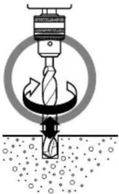
natural_image
Diagram of a drill bit being inserted into a pile of material, showing motion arrows (no text or symbols)| English Deutsch | Eλληνικά Polski | |||
| 1 | Drill chuck | Bohrfutter | Σφιγκτήρας δραπάνου | Uchwyt wiertarski |
| 2 | Chuck wrench | Futterschlüssel | Κλειδί σφιγκτήρα | Klucz do uchwytu wiertarskiego |
| 3 | Tighten Anziehen Σφίξτε | Dokręcanie | ||
| 4 | Loosen | Lösen | Χαλαρώστε | Luzowanie |
| 5 | Sleeve | Manschette | Συνδετικός δακτύλιος | Tuleja |
| 6 | Ring | Ring | Δακτύλιος | Pierścień |
| 7 | Side handle | Seitengriff | Πλευρική λαβή | Uchwyt boczny |
| 8 | Switch trigger | Abzugschalter | Σκανδάλη διακόπτης | Spust włącznika |
| 9 | Rotational change lever | Drehwechselknopf | Περιστροφικός μοχλός αλλαγής | Dźwignia zmiany kierunku obrotów |
| 10 | (R) mark | Markierung (R) | (R) σημάδι | Symbol (R) |
| 11 | (L) mark | Markierung (L) | (L) σημάδι | Symbol (L) |
| 12 | Depth gauge | Tiefenlehre | Μετρητής βάθους | Ogranicznik głębokości |
| 13 | Change lever | Umschalthebel | Μοχλός αλλαγής | Dźwignia przełącznika |
| 14 | Impact | Schlagbohre | Κρούση | Uderzenia |
| 15 | Rotation | Bohren | Περιστροφή | Obroty |
| 16 | Stopper | Stopper | Στόπερ | Zatyczka |
| Magyar | Čeština | Türkçe | Românâ | |
| 1 | Fúrótokmány | Sklíčidlo | Matkap mandreni | Prindere burghiu |
| 2 | Tokmánykulcs | Klíč sklíčidla | Mandren anahtarı | Cheie eliberare |
| 3 | Megszorítani | Utažení | Sıkıştırma | Strângere |
| 4 | Kiengedni | Povolení | Gevşetme | Eliberare |
| 5 | Karmantyú | Objímka | Manşon | Cartuş |
| 6 | Gyűrű | Kroužek | Halka | Inel |
| 7 | Oldalfogantyú | Boční držadlo | Yan kol | Mâner lateral |
| 8 | Kapcsoló | Spoušť | Anahtar tetiği | Trăgaci de schimbare |
| 9 | Forgásirány-váltó kar | Páčka pro změnu směru otáčení | Dönüşlü değiştirme kolu | Pârghie de schimbare rotativă |
| 10 | (R) - jobbra forgásirány-jelölés | Znak pravého chodu (R) | (R) işareti | (R) semn |
| 11 | (L) - jobbra forgásirány-jelölés | Znak levého chodu (L) | (L) işareti | (L) semn |
| 12 | Mélységmérő | Měřítko hloubky | Derinlik ölçme aleti | Etalon adâncime |
| 13 | Üzemmod váltó | Přepínač | Değiştirme kolu | Pîrghie de schimbare |
| 14 | Terhelés | Příklep | Darbe | Impact |
| 15 | Forgás | Rotace | Devir | Rotație |
| 16 | Ütköző | Zarážka | Derinlik mesnedi | Dispozitiv de oprire |
| Slovenščina | Slovenčina | Українська | Қазақстан | |
| 1 | Vrtalna vpenjalna glava | Skľičidlo | Патрон дриля | Бүргылау патроны |
| 2 | Ključ za vpenjalno glavo | Kľúč skľúčidla | Ключ патрона | Патрон кілті |
| 3 | Priviti Utiahnutie Затягнути | Тартыңыз | ||
| 4 | Odviti Povolenie Послабити | Босатыңыз | ||
| 5 | Obojka Objímka Гільза | Муфта | ||
| 6 | Obroč | Krúžok | Кільце | Сақина |
| 7 | Stranska ročica | Rukovăť | Бічна рукоятка | Бүйірлік түтқа |
| 8 | Stikalni sprožilec | Vypínač | Перемикач | Ажыратқыш шүріппесі |
| 9 | Vrtljivi izbirni vzvod | Páčka pre zmenu smeru otačania | Важіль зміни обертання | Айналатын өзгерту иінтірегі |
| 10 | Oznaka desno (R) | Znak pravého chodu (R) | Знак (R) - вправо | (R) белгісі |
| 11 | Oznaka levo (L) | Znak l'avého chodu (L) | Знак (L) - вліво | (L) белгісі |
| 12 | Merilnik globine | Hĺbkový | Обмежувач глибини | Терендік көрсеткіші |
| 13 | Preklopni vzvod | Prepínač | Регулювальний важіль | Өзгерту иінтірегі |
| 14 | Udarno vrtanje | Príklep | Удар | Сокқы |
| 15 | Rotacijsko vrtanje | Otáčanie | Обертання | Айналу |
| 16 | Mašilo | Zarážka | Стопор | Токтатқыш |
Read all safety warnings and all instructions.
Failure to follow the warnings and instructions may result in electric shock, fire and/or serious injury.
Save all warnings and instructions for future reference.
The term “power tool” in the warnings refers to your mains-operated (corded) power tool or battery-operated (cordless) power tool.
1) Work area safety
a) Keep work area clean and well lit.
Cluttered or dark areas invite accidents.
b) Do not operate power tools in explosive atmospheres, such as in the presence of fl ammable liquids, gases or dust.
Power tools create sparks which may ignite the dust or fumes.
c) Keep children and bystanders away while operating a power tool.
Distractions can cause you to lose control.
2) Electrical safety
a) Power tool plugs must match the outlet.
Never modify the plug in any way.
Do not use any adapter plugs with earthed (grounded) power tools.
Unmodifi ed plugs and matching outlets will reduce risk of electric shock.
b) Avoid body contact with earthed or grounded surfaces, such as pipes, radiators, ranges and refrigerators.
There is an increased risk of electric shock if your body is earthed or grounded.
c) Do not expose power tools to rain or wet conditions.
Water entering a power tool will increase the risk of electric shock.
d) Do not abuse the cord. Never use the cord for carrying, pulling or unplugging the power tool.
Keep cord away from heat, oil, sharp edges or moving parts.
Damaged or entangled cords increase the risk of electric shock.
e) When operating a power tool outdoors, use an extension cord suitable for outdoor use.
Use of a cord suitable for outdoor use reduces the risk of electric shock.
f) If operating a power tool in a damp location is unavoidable, use a residual current device (RCD) protected supply.
Use of an RCD reduces the risk of electric shock.
3) Personal safety
a) Stay alert, watch what you are doing and use common sense when operating a power tool. Do not use a power tool while you are tired or under the influence of drugs, alcohol or medication.
A moment of inattention while operating power tools may result in serious personal injury.
b) Use personal protective equipment. Always wear eye protection.
Protective equipment such as dust mask, non-skid safety shoes, hard hat, or hearing protection used for appropriate conditions will reduce personal injuries.
c) Prevent unintentional starting. Ensure the switch is in the off-position before connecting to power source and/or battery pack, picking up or carrying the tool.
Carrying power tools with your finger on the switch or energising power tools that have the switch on invites accidents.
d) Remove any adjusting key or wrench before turning the power tool on.
A wrench or a key left attached to a rotating part of the power tool may result in personal injury.
e) Do not overreach. Keep proper footing and balance at all times.
This enables better control of the power tool in unexpected situations.
f) Dress properly. Do not wear loose clothing or jewellery. Keep your hair, clothing and gloves away from moving parts.
Loose clothes, jewellery or long hair can be caught in moving parts.
g) If devices are provided for the connection of dust extraction and collection facilities, ensure these are connected and properly used.
Use of dust collection can reduce dust related hazards.
4) Power tool use and care
a) Do not force the power tool. Use the correct power tool for your application.
The correct power tool will do the job better and safer at the rate for which it was designed.
b) Do not use the power tool if the switch does not turn it on and off.
Any power tool that cannot be controlled with the switch is dangerous and must be repaired.
c) Disconnect the plug from the power source and/or the battery pack from the power tool before making any adjustments, changing accessories, or storing power tools.
Such preventive safety measures reduce the risk of starting the power tool accidentally.
d) Store idle power tools out of the reach of children and do not allow persons unfamiliar with the power tool or these instructions to operate the power tool.
Power tools are dangerous in the hands of untrained users.
e) Maintain power tools. Check for misalignment or binding of moving parts, breakage of parts and any other condition that may affect the power tool's operation.
If damaged, have the power tool repaired before use.
Many accidents are caused by poorly maintained power tools.
f) Keep cutting tools sharp and clean.
Properly maintained cutting tools with sharp cutting edges are less likely to bind and are easier to control.
g) Use the power tool, accessories and tool bits etc. in accordance with these instructions, taking into account the working conditions and the work to be performed.
Use of the power tool for operations different from those intended could result in a hazardous situation.
5) Service
a) Have your power tool serviced by a qualified repair person using only identical replacement parts.
This will ensure that the safety of the power tool is maintained.
PRECAUTION
Keep children and infirm persons away.
When not in use, tools should be stored out of reach of children and infirm persons.
IMPACT DRILL SAFETY WARNINGS
- Wear ear protectors when impact drilling.
Exposure to noise can cause hearing loss.
- Use auxiliary handle(s), if supplied with the tool.
Loss of control can cause personal injury.
-
Hold power tool by insulated gripping surfaces, when performing an operation where the cutting accessory may contact hidden wiring or its own cord. Cutting accessory contacting a "live" wire may make exposed metal parts of the power tool "live" and could give the operator an electric shock.
-
When boring concrete or similar hard materials in IMPACT mode, turn the rotational change lever to the R-mark. (Fig. 9)
SPECIFICATIONS
| Model | DV13SS | DV13VSS | DV16SS | DV16VSS | |
| Voltage (by areas)* | (110 V, 220 V, 230 V, 240 V)~ | ||||
| Power input* | 550 W | 600 W | |||
| Reversible | None Yes N | None Yes | |||
| No load speed | 2900 min-1 | 0 – 2900 min1 | 2900 min-1 | 0 – 2900 min-1 | |
| Drill chuck capacity | 13 mm | ||||
| Capacity | Steel | 13 mm | |||
| Concrete | 13 mm | 16 mm | |||
| Wood | 20 mm | 25 mm | |||
| Full load impact rate | 29000 min-1 | ||||
| Weight (without cord) | 1.4 kg | 1.5 kg | |||
* Be sure to check the nameplate on product as it is subject to change by areas.
STANDARD ACCESSORIES
| Model Drill chuck spec. Standard accessories | ||
| DV13SS | Keyed Chuck | wrench .....1 |
| DV13VSS | Keyed Chuck wrench .....1 | |
| Keyless | Case .....1Depth gauge .....1Side handle .....1 | |
| DV16SS Keyed | Chuck wrench .....1Depth gauge .....1Side handle .....1 | |
| DV16VSS | Keyed | Chuck wrench .....1Depth gauge .....1Side handle .....1 |
| Keyless | Case .....1Depth gauge .....1Side handle .....1 | |
Standard accessories are subject to change without notice.
OPTIONAL ACCESSORIES (SOLD SEPARATELY)
○ Impact Drill Bit (for concrete)
3.2 mm - 20 mm dia.
Optional accessories are subject to change without notice.
APPLICATIONS
○ By combined actions of ROTATION and IMPACT:
Boring holes in hard materials (concrete, marble, granite, tiles, etc.)
○ By ROTATIONAL action:
Boring holes in metal, wood and plastic.
PRIOR TO OPERATION
1. Power source
Ensure that the power source to be utilized conforms to the power requirements specified on the product nameplate.
2. Power switch
Ensure that the power switch is in the OFF position. If the plug is connected to a receptacle while the power switch is in the ON position, the power tool will start operating immediately, inviting serious accident.
3. Extension cord
When the work area is removed from the power source. Use an extension cord of sufficient thickness and rated capacity. The extension cord should be kept as short as practicable.
4. Selecting the appropriate drill bit
○ When boring concrete or stone
Use the drill bits specified in the Optional Accessories.
○ When boring metal or plastic
Use an ordinary metalworking drill bit.
○ When boring wood
Use an ordinary woodworking drill bit.
However, when drilling 6.5 mm or smaller holes, use a metalworking drill bit.
5. Mounting and dismounting of the bit
For Drill chuck with chuck wrench (Fig. 1)
(1) Open the chuck jaws, and insert the bit into the chuck.
(2) Place the chuck wrench in each of the three holes in the chuck, and turn it in the clockwise direction (viewed from the front side). Tighten securely.
(3) To remove the bit, place the chuck wrench into one of the holes in the chuck and turn it in the counterclockwise direction.
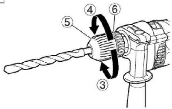
For keyless chuck (Fig. 2)
(1) Open the chuck jaws, and insert the bit into the chuck.
To open the chuck jaws, hold the ring while turning the sleeve in the counterclockwise direction (viewed from the front side).
(2) Firmly grasp the ring and turn the sleeve in the clockwise direction. Tighten securely.
(3) To remove the bit, firmly grasp the ring and turn the sleeve in the counterclockwise direction.
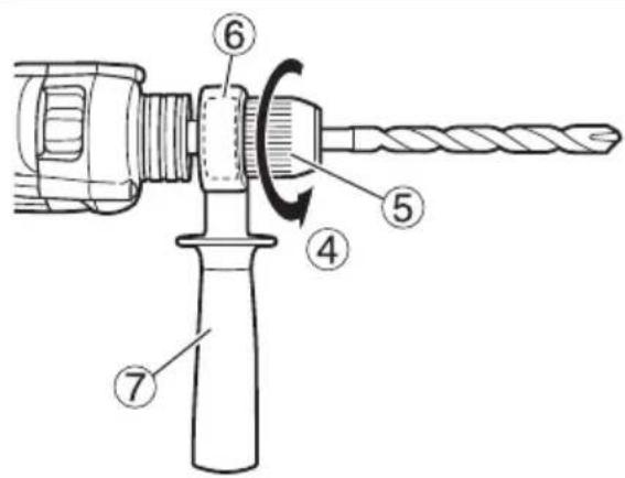
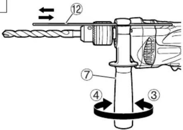
(4) When the sleeve does not become loose any further, fix the side handle to retaining ring, hold side handle firmly, then turn the sleeve to loosen by hand. (Fig. 3)
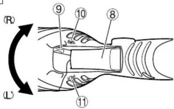
6. Check the rotational direction (Fig. 4) (DV13VSS, DV16VSS only)
The bit rotates clockwise (viewed from the rear side) by turning the rotational change lever to R-mark.
The rotational change lever is returned to the L-mark to turn the bit counterclockwise.
(The (L) and (R) marks are provided on the body.)
CAUTION
Always use the impact drill with clockwise rotation, when using it as an impact drill.
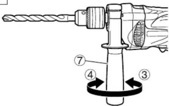
7. Fixing the side handle (Fig. 5)
Attach the side handle to the mounting part.
Rotate the side handle grip in a clockwise direction to secure it.
Set the side handle to a position that is suited to the operation and then securely tighten the side handle grip.
To attach a depth gauge on the side handle, insert the gauge into the U-shaped groove on the side handle, adjust the position of the depth gauge in accordance with the desired depth of the hole, and firmly tighten the side handle grip. (Fig. 6)
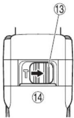
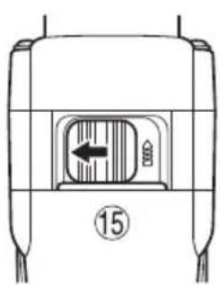
8. IMPACT to ROTATION changeover (Fig. 7)
Shift the change lever between the right and left positions to switch easily between IMPACT (rotation and impact) and ROTATION (rotation only), respectively.
To bore holes in hard materials such as concrete, stone and tiles, shift the change lever to the right-hand position (as indicated by the T mark).
The drill bit operates by the combined actions of impact and rotation.
To bore holes in metal, wood and plastic, shift the change lever to the left-hand position (as indicated by the 3 mark). The drill bit operates by rotational action only, as in the case of a conventional electric drill. CAUTION
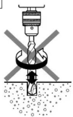
☐ Do not use the Impact Drill in the IMPACT function if the material can be bored by rotation only. Such action will not only reduce drill efficiency, but may also damage the drill tip.
○ Operating the Impact Drill with the change lever in mid-position may result in damage. When switching, make sure that you shift the change lever to the correct position.
HOW TO USE
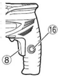
1. Switch operation (Fig. 8)
○ When the trigger is depressed, the tool rotates. When the trigger is released, the tool stops.
○ Pulling the trigger and pushing the stopper, it keeps the switched-on condition which is convenient for continuous running. When switching off, the stopper can be disconnected by pulling the trigger again.
< DV13VSS, DV16VSS only >
☐ The rotational speed of the drill can be controlled by varying the amount that the trigger switch is pulled. Speed is low when the trigger switch is pulled slightly and increases as the trigger switch is pulled more.
2. When using as a Drill or an Impact Drill
(1) Pressing force of the drill
You cannot drill holes more quickly even if you press the drill with a stronger force than necessary. It not only damages tip of drill bit and decreases the efficiency of operation, but also shortens the life of the drill tip.
(2) In case of penetrating holes
Drill bits can be broken when the material being drilled is penetrated. It is important to decrease pressing force just before penetrating.
CAUTION
In continuous operation, conduct no-load operation for five seconds after completing a drilling job.
(3) When a thick drill bit is used
Your arm is subjected to larger reaction force when a thicker drill bit is used. Be careful not to be moved by the reaction force. For this, establish a foothold, hold the unit tightly with both hands perpendicularly to the material being drilled.
MAINTENANCE AND INSPECTION
1. Inspecting the drill bits
Since use of an abraded drill bits will cause motor malfunctioning and degraded efficiency, replace the drill bits with a new one or resharpening without delay when abrasion is noted.
2. Inspecting the mounting screws
Regularly inspect all mounting screws and ensure that they are properly tightened. Should any of the screws be loose, retighten them immediately. Failure to do so could result in serious hazard.
3. Maintenance of the motor
The motor unit winding is the very “heart” of the power tool. Exercise due care to ensure the winding does not become damaged and/or wet with oil or water.
4. Inspecting the carbon brushes
For your continued safety and electrical shock protection, carbon brush inspection and replacement on this tool should ONLY be performed by a HiKOKI AUTHORIZED SERVICE CENTER.
5. Replacing supply cord
If the replacement of the supply cord is necessary, this has to be done by HiKOKI Authorized Service Center in order to avoid a safety hazard.
CAUTION
In the operation and maintenance of power tools, the safety regulations and standards prescribed in each country must be observed.
GUARANTEE
We guarantee HiKOKI Power Tools in accordance with statutory/country specific regulation. This guarantee does not cover defects or damage due to misuse, abuse, or normal wear and tear. In case of complaint, please send the Power Tool, undismantled, with the GUARANTEE CERTIFICATE found at the end of this Handling instruction, to a HiKOKI Authorized Service Center.
NOTE
Due to HiKOKI's continuing program of research and development, the specifications herein are subject to change without prior notice.
Information concerning airborne noise and vibration
The measured values were determined according to EN60745 and declared in accordance with ISO 4871.
The typical A-weighted sound pressure level: 92 dB (A)
The typical A-weighted sound power level: 103 dB (A)
Uncertainty KpA: 3 dB (A).
Wear hearing protection.
Vibration total values (triax vector sum) determined according to EN60745.
Impact drilling into concrete:
Vibration emission value ah, ID = 19.9 m/s²
Uncertainty K = 4.9 m/s ^2
Drilling into metal:
Vibration emission value ah, D = 6.4 m/s ^2
Uncertainty K = 1.5 m/s ^2
The declared vibration total value has been measured in accordance with a standard test method and may be used for comparing one tool with another.
It may also be used in a preliminary assessment of exposure.
WARNING
☐ The vibration emission during actual use of the power tool can differ from the declared total value depending on the ways in which the tool is used.
- Identify safety measures to protect the operator that are based on an estimation of exposure in the actual conditions of use (taking account of all parts of the operating cycle such as the times when the tool is switched off and when it is running idle in addition to the trigger time).
Hikoki Power Tools Romania S.R.L.
Ring Road, No. 66, Mustang Traco Warehouses,
Warehouse
No.1, Pantelimon City, 077145, Ilfov County, Romania

- PRECAUTION
- IMPACT DRILL SAFETY WARNINGS
- OPTIONAL ACCESSORIES (SOLD SEPARATELY)
- APPLICATIONS
- PRIOR TO OPERATION
- Power source
- Power switch
- Extension cord
- Selecting the appropriate drill bit
- Mounting and dismounting of the bit
- For Drill chuck with chuck wrench (Fig. 1)
- For keyless chuck (Fig. 2)
- Check the rotational direction (Fig. 4) (DV13VSS, DV16VSS only)
- CAUTION
- Fixing the side handle (Fig. 5)
- IMPACT to ROTATION changeover (Fig. 7)
- HOW TO USE
- Switch operation (Fig. 8)
- When using as a Drill or an Impact Drill
- MAINTENANCE AND INSPECTION
- Inspecting the drill bits
- Inspecting the mounting screws
- Maintenance of the motor
- Inspecting the carbon brushes
- Replacing supply cord
- GUARANTEE
- NOTE
- Information concerning airborne noise and vibration
- WARNING
- Hikoki Power Tools Romania S.R.L.
Brand : HiKOKI
Model : DV16VSS
Category : Drill