KM 360 - CONVERTING INSTRUCTIONS - Fridge MIELE - Free user manual and instructions
Find the device manual for free KM 360 - CONVERTING INSTRUCTIONS MIELE in PDF.

User questions about KM 360 - CONVERTING INSTRUCTIONS MIELE
0 question about this device. Answer the ones you know or ask your own.
Ask a new question about this device
Download the instructions for your Fridge in PDF format for free! Find your manual KM 360 - CONVERTING INSTRUCTIONS - MIELE and take your electronic device back in hand. On this page are published all the documents necessary for the use of your device. KM 360 - CONVERTING INSTRUCTIONS by MIELE.
USER MANUAL KM 360 - CONVERTING INSTRUCTIONS MIELE
The cooktop should have been ordered for connection to either natural gas or LP gas.
The included regulator corresponds with the gas type of the cooktop. Verify before installing. See, "To convert the regulator".
If the appliance is to be connected to a type of gas other than it was originally configured for, both the regulator and burners must be converted.

WARNING
The conversion kit must be installed by a qualified technician in accordance with the manufacturer's instructions and all applicable local and national codes. If the information in these instructions is not followed exactly, a fire, explosion or production of carbon monoxide may result causing property damage, personal injury or loss of life. The qualified technician is responsible for the proper installation of this kit. The installation is not proper and complete until the operation of the converted appliance is checked as specified in these instructions.
To convert the regulator
- Unscrew the hexagonal nut (silver cap) located on the top of the regulator.
Make sure that the spring stays in place. - Flip over the cap and screw it back in place.
A stamp should be visible on top of the cap or at the bottom of the center hole when converted ("LP" for LPG and "NG" for Natural gas).
To convert the burners
Turn off the main gas supply (if the appliance has already been installed) and disconnect the appliance from the main electrical power supply before proceeding.
The following jets and needle valves should be installed into their respective burners. Follow codes accordingly.
| Code | Jet size (Ø mm) | Code | Needle valve size (Ø mm) | |
| Natural gas | ||||
| Normal burner | 150 | 1.50 | 60 | 0,60 |
| Fast burner | 165 | 1.65 | 65 | 0.65 |
| Propane (LP) | ||||
| Normal burner | 72 | 0.72 | 29 | 0.29 |
| Fast burner | 92 | 0.92 | 40 | 0.40 |
Changing the needle valves
- Insert a screwdriver through the holes in the bottom of the cooktop, ① , and loosen the needle valves. Remove them with a pair of pliers.
Install and tighten the new needle valves.
Changing the Jets
Remove the grates, the burner cap, ①, and the burner head, ②.
Using a 7 mm nut driver or socket wrench, unscrew and remove the jet, ③.
Install the new jet and reassemble the above parts in the reverse order.
- Save the jets and needle valves removed from the appliance for future use.
After conversion
After converting the cooktop affix the label supplied with the conversion kit next to the data plate underneath the appliance.
- Check that there are no leaks, e.g. with soapy water.
- Check that the burner is correctly assembled.
Turn on the gas supply.
Light each of the burners in turn.
When set at "low" or when the control knob is quickly turned from "high to "low" the flame should not go out.
When set at "high" the gas flame must burn with the center clearly visible.
The cooktop should have been ordered for connection to either natural gas or LP gas.
The included regulator corresponds with the gas type of the cooktop. Verify before installing. See, "To convert the regulator".
If the appliance is to be connected to a type of gas other than it was originally configured for, both the regulator and burners must be converted.
WARNING
The conversion kit must be installed by a qualified technician in accordance with the manufacturer's instructions and all applicable local and national codes. If the information in these instructions is not followed exactly, a fire, explosion or production of carbon monoxide may result causing property damage, personal injury or loss of life. The qualified technician is responsible for the proper installation of this kit. The installation is not proper and complete until the operation of the converted appliance is checked as specified in these instructions.
To convert the regulator:
- Unscrew the hexagonal nut (silver cap) located on the top of the regulator.
- Make sure that the spring stays in place.
- Flip over the cap and screw it back in place.
A stamp should be visible on top of the cap or at the bottom of the center hole when converted ("LP" for LPG and "NG" for Natural gas).
To convert the burners
Turn off the main gas supply (if the appliance has already been installed) and disconnect the appliance from the main electrical power supply before proceeding.
The following jets and needle valves should be installed into their respective burners. Follow codes accordingly.
Conversion table KM 342
| Code | Jet size (Ø mm) | Code | Needle valve size (Ø mm) | |
| Natural gas | ||||
| Normal burner | 140 | 1.40 | 62 | 0.62 |
| Fast burner | 167 | 1.67 | 78 | 0.78 |
| Wok burner inner outer | 34 190 | No. 34 1.90 | 40 88 | 0.40 0.88 |
| Propane (LP) | ||||
| Normal burner | 90 | 0.90 | 41 | 0.41 |
| Fast burner | 103 | 1.03 | 45 | 0.45 |
| Wok burner inner outer | 7 109 | No. 7 1.09 | 25 54 | 0.25 0.54 |
Conversion table KM 344
| Code | Jet size (Ø mm) | Code | Needle valve size (Ø mm) | |
| Natural gas | ||||
| Normal burner | 140 | 1.40 | 62 | 0.62 |
| Fast burner | 167 | 1.67 | 78 | 0.78 |
| Wok burner leftinnerouter | 34190 | No. 341.90 | 4088 | 0.400.88 |
| Wok burner rightinnerouter | 34195 | No. 341.95 | 4088 | 0.400.88 |
| Propane (LP) | ||||
| Normal burner | 90 | 0.90 | 41 | 0.41 |
| Fast burner | 103 | 1.03 | 45 | 0.45 |
| Wok burner leftinnerouter | 7109 | No. 71.09 | 2554 | 0.250.54 |
| Wok burner rightinnerouter | 7112 | No. 71.12 | 2554 | 0.250.54 |
To change the jets and needle valves the appliance has to be opened by removing the burners.
Normal/Fast burner
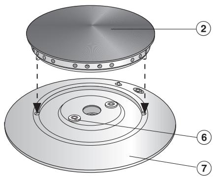
Remove the grates and the burner cap, ②.
Loosen the screws, ⑥ and take off the burner base, ⑦
Wok burner
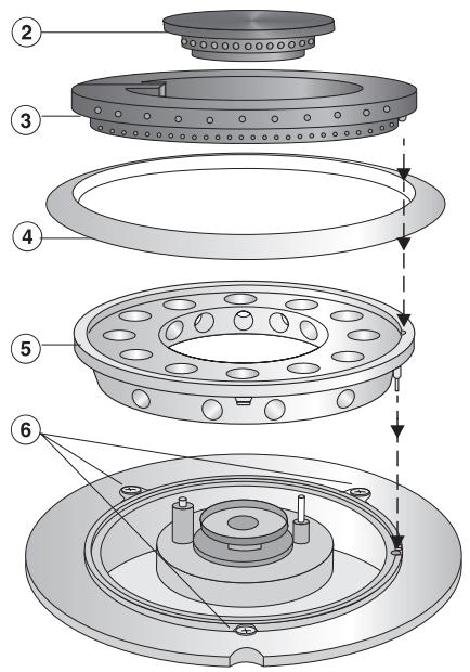
- Remove the grates, the small burner cap, ②, the large burner cap, ③, the burner ring, ④, and the burner base, ⑤.
Loosen the screws, 6. - When all burners have been taken off, pull all control knobs off of the cooktop.
Now the cooktop surface can be taken off.
Changing the needle valves
Normal/Fast burner
Remove the ignition switch, ①.
- Loosen the needle valve, ②, with a screwdriver and remove with a pair of pliers.
Install the new needle valve according to the conversion table and tighten.
Wok burner
Remove the ignition switch, ①.
- Loosen the small, ② , and large, ③ , needle valves with a screwdriver and remove them with a pair of pliers.
Install the new needle valves according to the conversion table and tighten.
Changing the jets
Normal/Fast burner
Using a 7 mm nut driver or socket wrench, unscrew and remove the jet.
Install the new jet according to the conversion table.
- Save the jets and needle valves removed from the appliance for future use.
Wok burner
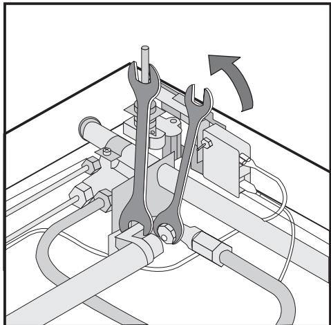
Use a 10 mm wrench to remove the jet. While doing this, use a 13 mm wrench to hold the gas tube to prevent it from twisting.
Install the new jet using the same procedure.
- Save the jets and needle valves removed from the appliance for future use.
Changing the small burner jet

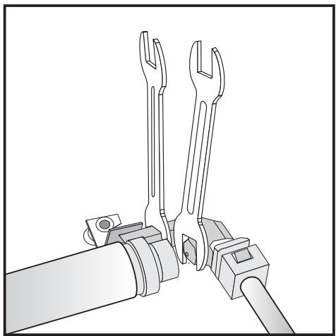
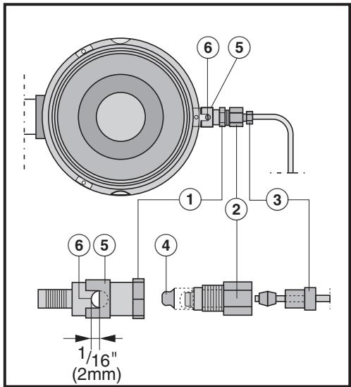
- First loosen the fitting, ③ , using an 8 mm wrench. While doing so hold the connector, ② , with a 12 mm wrench to prevent the tubing from twisting.
- Then remove the connector, ② , from the fitting, ① , using two 12 mm wrenches.
Remove the jet, ④ , and replace it with the new jet.
Slide the air sleeve, ⑤ , until there is a 1 / _16'' (2 mm) gap between the sleeve and the air vent, ⑥ , as shown.
Reassemble the burners and test the unit for leaks. The cooktop can be operated without the cooktop surface in place by igniting the flames with a match.
①,③ Fittings
② Connector
④ Small burner jet
⑤ Air sleeve
⑥ Airvent
Check the intake air
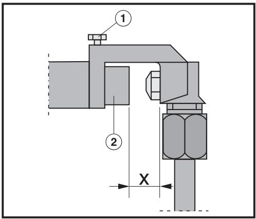
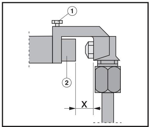
To adjust the gap loosen the lock screw, ①, and slide the air sleeve, ②, in or out as necessary.
- Tighten the lock screw, ①, and reassemble the cooktop in the reverse order.
Check all fittings for gas leaks before reassembling the cooktop.
① Lock screw
② Air sleeve
Gap X must measure:
- 1 / 2^n (13 mm) for natural gas
- 1 / 4" (6.5 mm) for LP gas
After conversion
- After converting the cooktop, affix the label supplied with the conversion kit next to the data plate underneath the appliance.
- Check that the regulator has been converted.
- Check that there are no leaks e.g. with soapy water.
- Reassemble the appliance in reverse order.
- Check that the burner is correctly assembled.
- Turn on the gas supply.
- Light each burner in turn.
The flame should not go out when set at "low" or when the control knob is quickly turned from "high" to "low".
When set at "high" the gas flame must burn with the center clearly visible.
When installed properly, the flame will be steady and quiet. It will also have a sharp, blue inner core that will vary in size depending on the burner. Flame adjustment will not be necessary.
The cooktop should have been ordered for connection to either natural gas or LP gas.
The included regulator corresponds with the gas type of the cooktop. Verify before installing. See, "To convert the regulator".
If the appliance is to be connected to a type of gas other than it was originally configured for, both the regulator and burners must be converted.

WARNING
The conversion kit must be installed by a qualified technician in accordance with the manufacturer's instructions and all applicable local and national codes. If the information in these instructions is not followed exactly, a fire, explosion or production of carbon monoxide may result causing property damage, personal injury or loss of life. The qualified technician is responsible for the proper installation of this kit. The installation is not proper and complete until the operation of the converted appliance is checked as specified in these instructions.
To convert the regulator
- Unscrew the hexagonal nut (silver cap) located on the top of the regulator.
Make sure that the spring stays in place. - Flip over the cap and screw it back in place.
A stamp should be visible on top of the cap or at the bottom of the center hole when converted ("LP" for LPG and "NG" for Natural gas).
To convert the burners
Turn off the main gas supply (if the appliance has already been installed) and disconnect the appliance from the main electrical power supply before proceeding.
To change the jets and needle valves the appliance has to be opened by removing the burners.
Removing the burners
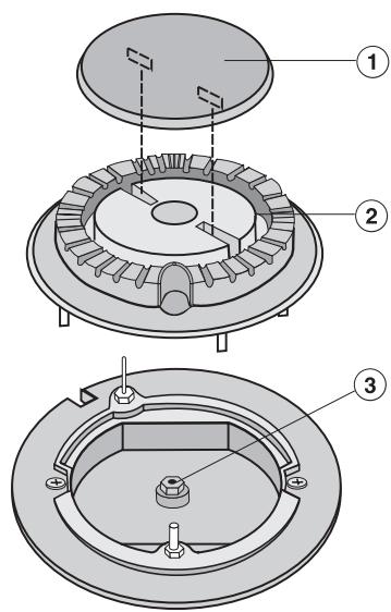
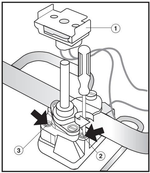
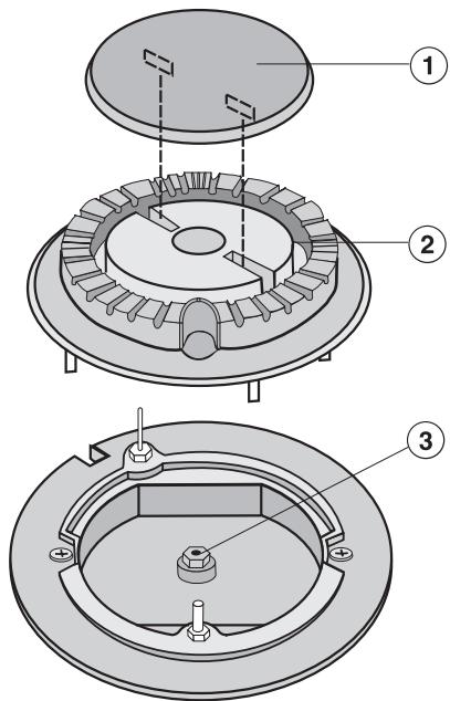
Remove the grates, the burner cap, ①, the burner base, ②.
- Loosen the screws, ③ , and take off the cooktop surface.
The following jets and needle valves should be installed into their respective burners. Follow codes accordingly.
Conversion table KM 360
| Code | Jet size (Ø mm) | Code | Needle valve size (Ø mm) | |
| Natural gas | ||||
| Auxiliary burner | 92 | 0.92 | 42 | 0.42 |
| Normal burner | 115 | 1.15 | 52 | 0.52 |
| Fast burner | 165 | 1.65 | 60 | 0.60 |
| Propane (LP) | ||||
| Auxiliary burner | 56 | 0.56 | 23 | 0.23 |
| Normal burner | 72 | 0.72 | 29 | 0.29 |
| Fast burner | 92 | 0.92 | 40 | 0.40 |
Changing the needle valves
All burners

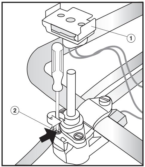
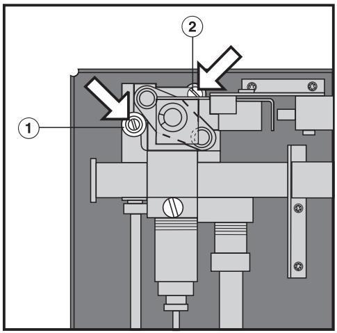
Remove the ignition switch, ①.
- Loosen the needle valve, ②, with a screwdriver and remove with a pair of pliers.
Install the new needle valve according to the conversion table and tighten.
- Check that the regulator has been converted.
- Check that there are no leaks e.g. with soapy water.
Reassemble the appliance in reverse order.
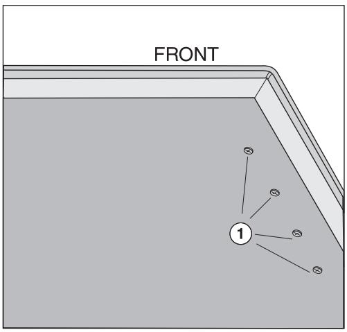
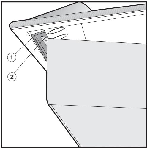
Position the cooktop surface as shown in the illustration, pull it forward and push it backwards until the angle, ①, locks in place under the lip, ②. Then lower the cooktop surface onto the lower portion.
Screw on the burner bases.
Replace the control knobs.

Changing the jets
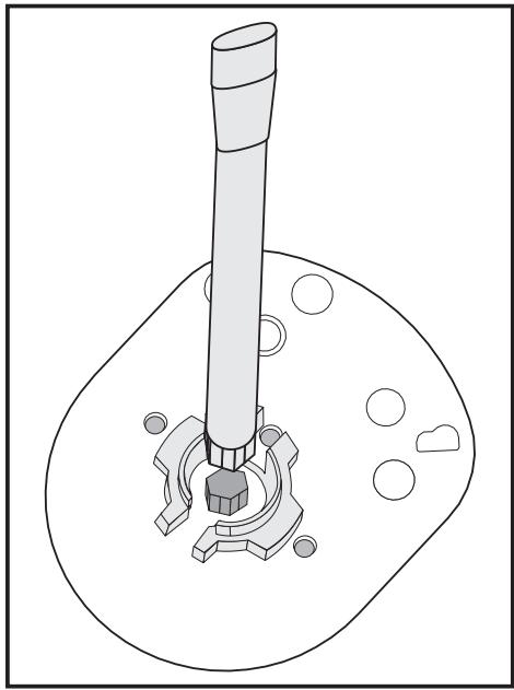
Using a 7 mm nut driver or socket wrench, unscrew the jet, ③.
Install the new jet according to the table and reassemble the burner head, ② , burner cap, ① , and grates.
- Save the jets and needle valves removed from the appliance for future use.
Check that there are no leaks e.g. with soapy water.
Reinsert the burner control knobs.
Turn on the gas supply.
Light each of the burners in turn.
After converting the cooktop, affix the label supplied with the conversion kit next to the data plate underneath the appliance.
The flame should not go out when set at "low" or when the control knob is quickly turned from "high" to "low".
When set at "high" the gas flame must burn with the center clearly visible.
When installed properly, the flame will be steady and quiet. It will also have a sharp, blue inner core that will vary in size depending on the burner. Flame adjustment will not be necessary.
The cooktop should have been ordered for connection to either natural gas or LP gas.
The included regulator corresponds with the gas type of the cooktop. Verify before installing. See, "To convert the regulator".
If the appliance is to be connected to a type of gas other than it was originally configured for, both the regulator and burners must be converted.

WARNING
The conversion kit must be installed by a qualified technician in accordance with the manufacturer's instructions and all applicable local and national codes. If the information in these instructions is not followed exactly, a fire, explosion or production of carbon monoxide may result causing property damage, personal injury or loss of life. The qualified technician is responsible for the proper installation of this kit. The installation is not proper and complete until the operation of the converted appliance is checked as specified in these instructions.
To convert the regulator
- Unscrew the hexagonal nut (silver cap) located on the top of the regulator.
Make sure that the spring stays in place. - Flip over the cap and screw it back in place.
A stamp should be visible on top of the cap or at the bottom of the center hole when converted ("LP" for LPG and "NG" for Natural gas).
To convert the burners
Turn off the main gas supply (if the appliance has been installed) and disconnect the appliance from the main electrical power supply before proceeding.
The following jets and needle valves should be installed into their respective burners. Follow codes accordingly.
| Code | Jet size (Ø mm) | Code | Needle valve size (Ø mm) | |
| Natural gas | ||||
| Front burner | 115 | 1.15 | 52 | 0.52 |
| Rear burner | 155 | 1.55 | 60 | 0.60 |
| Propane (LP) | ||||
| Front burner | 72 | 0.72 | 29 | 0.29 |
| Rear burner | 92 | 0.92 | 40 | 0.40 |
Changing the needle valves
- Insert a screwdriver through the holes in the bottom of the cooktop, ① , and loosen the needle valves. Remove them with a pair of pliers.
Install and tighten the new needle valves.
Changing the jets
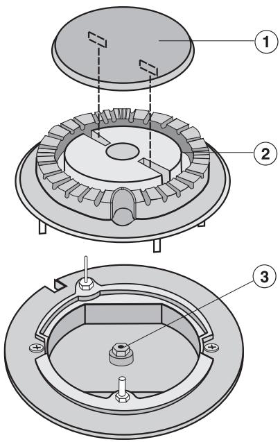
Remove the grates, burner cap, ①, and the burner head, ②.
Using a 7 mm nut driver or socket, unscrew the jet, ③.
Install the new jet and reassemble the above parts in the reverse order.
To convert the burners
Turn off the main gas supply (if the appliance has been installed) and disconnect the appliance from the main electrical power supply before proceeding.
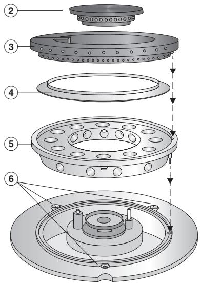
- Remove the grates, the burner cap, ② , the large burner cap, ③ , the burner ring, ④ , and the burner base, ⑤ .
Loosen the screws, 6.
Pull the control knob off of the cooktop.
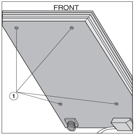
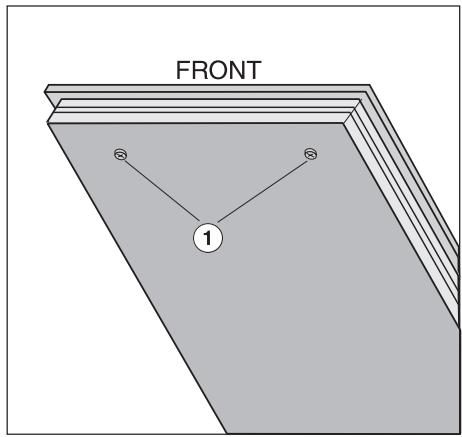
Using a T 20 Torx screwdriver, remove the 4 screws, ① , holding the upper and lower housings together.
Securing the top level, carefully separate it from the lower housing.
Changing the jets
The following jets and needle valves should be installed into their respective burners.
| Code | Jet size (Ø mm) | Code | Needle valve size (Ø mm) | |
| Natural gas | ||||
| Large burner | 200 | 2.00 | 88 | 0.88 |
| Small burner | 34 | No 34 | 60 | 0.40 |
| Propane (LP) | ||||
| Large burner | 120 | 1.20 | 54 | 0.54 |
| Small burner | 7 | No 7 | 25 | 0.25 |
Changing the large burner jet
Use a 10 mm wrench to remove the jet. While doing this, use a 13 mm wrench to hold the gas tube to prevent it from twisting.
Install the new jet using the same procedure.
Changing the needle valves
① Needle valve with small jet (0.25 for propane).
(2) Needle valve with large jet (0.54 for propane).
Using a small screwdriver, unscrew the needle valves and remove them with a pair of needle nose pliers.
Insert the new valves and screw them into place.
Changing the small burner jet
■ First loosen the fitting, ③ , using an 8 mm wrench. While doing so hold the connector, ② , with a 12 mm wrench to prevent the tubing from twisting.
- Then remove the connector, ② , from the fitting, ① , using two 12 mm wrenches.
Remove the jet, ④ , and replace it with the new jet.
Slide the air sleeve, ⑤ , until there is a 1 / _16^ (2 mm) gap between the sleeve and the air vent, ⑥ , as shown.
Reassemble the burners and test the unit for leaks. The cooktop can be operated without the cooktop surface in place by igniting the flames with a match.
①,③ Fittings
② Connector
④ Small burner jet
⑤ Air sleeve
⑥ Airvent
Check the intake air
① Lock screw
② Air sleeve
Gap X must measure:
- 1 / 2^n (13 mm) for natural gas
- 1 / 4'' (6.5mm) for LP (propane) gas
To adjust the gap, loosen the lock screw and slide the air sleeve in or out as necessary.
- Tighten the lock screw and reassemble the cooktop in reverse order.
Check all fittings for gas leaks before reassembling the cooktop.
After conversion
After converting the cooktop, affix the label supplied with the conversion kit on to the data plate over the type of gas stated.
Check that there are no leaks e.g, with soapy water.
- Check that the burner is correctly assembled.
Turn on the gas supply.
Light each of the burners in turn.
When set at "low" or when the control knob is quickly turned from "high" to low the flame should not go out.
When set at "high" the gas flame must burn with the center clearly visible.
55G, East Beaver Creek Road
Richmond Hill (Ontario) L4B 1E5
Telephone: (800) 643-5381
(905) 707-1171
Télécopieur: (905) 707-0177
www.miele.ca
National Headquarters
9 Independence Way
Princeton, NJ 08540
Phone: 800-843-7231
609-419-9898
Fax: 609-419-4298
www.mieleusa.com
Technical Service & Support Nationwide
Phone: 800-999-1360
Fax: 888-586-8056
Miele Limited

National Headquarters
55G East Beaver Creek Road
Richmond Hill, ON L4B 1E5
Phone: 800-643-5381
905-707-1171
Fax: 905-707-0177
www.miele.ca
info@miele.ca (general enquiries)
professional@miele.ca (commercial enquiries)
Mielecare National Service
Phone: 800-565-6435
905-850-7456
Fax: 905-850-6651
service@miele.ca (Tech. Service)