
KFT 7000 - Fridge MIELE - Free user manual and instructions
Find the device manual for free KFT 7000 MIELE in PDF.

User questions about KFT 7000 MIELE
0 question about this device. Answer the ones you know or ask your own.
Ask a new question about this device
Download the instructions for your Fridge in PDF format for free! Find your manual KFT 7000 - MIELE and take your electronic device back in hand. On this page are published all the documents necessary for the use of your device. KFT 7000 by MIELE.
USER MANUAL KFT 7000 MIELE
en Adjustable shelf with pivotable glass shelf – FlexiTray
es Balda con base giratoria - FlexiTray
natural_image
Diagram of a bathtub with arrows indicating flow or movement, no text or symbols presentnatural_image
Diagram of a door with a handle and circular button, no text or symbols presenttext_image
Diagram of a device casing with labeled component '1' and directional arrow indicating motion or movementtext_image
Technical diagram showing a mechanical assembly with labeled components and directional arrows indicating flow or movement.natural_image
Technical diagram of a mechanical assembly with two circular inset views showing internal components (no text or labels)text_image
Diagram showing hand positioning on a device with labeled step 1 and directional arrownatural_image
Diagram of a bathtub with airflow arrows indicating movement or circulation (no text or symbols)natural_image
Diagram of a device casing with a black arrow pointing to a circular button (no text or symbols)text_image
Technical diagram of a device casing with labeled component '1' and directional arrow indicating motion or movement.text_image
Technical diagram showing a mechanical assembly with labeled components and directional arrows indicating flow or movement.natural_image
Technical diagram of a mechanical component with two circular inset views showing internal features (no text or labels)text_image
Diagram showing hands operating a device with a numbered step labeled '1' pointing to the screen area.natural_image
Diagram of a bathroom sink with directional arrows indicating flow or movement (no text or symbols)natural_image
Diagram of a device casing with a circular button and an arrow pointing to it (no text or symbols)text_image
Diagram of a device casing with labeled component '1' and directional arrow indicating motion or movementtext_image
Technical diagram showing a mechanical assembly with labeled components and directional arrows indicating flow or movement.natural_image
Technical diagram of a mechanical assembly with two circular inset views showing internal components (no text or labels)text_image
Diagram showing hands installing or adjusting a device component with a numbered callout indicating step 1natural_image
Diagram of a bathroom sink with directional arrows indicating flow or movement (no text or symbols)natural_image
Diagram of a vehicle door with a black arrow pointing to the bottom-right corner (no text or symbols)text_image
Technical diagram of a device casing with labeled component '1' and directional arrow indicating motion or movement.text_image
Technical diagram showing a mechanical component with labeled parts and directional arrows indicating flow or assembly.natural_image
Technical line drawing of a mechanical assembly with two circular inset views showing internal components (no text or symbols)text_image
Diagram showing hands operating a device with a numbered step labeled '1'Tag bakken med forbindelsesknoppen pegende nedad, og tryk hårdt forbindelsesknoppen ned i slutpositionen i rillen ①.
■ Læg glasbunden på bakken.
natural_image
Diagram of a bathroom sink with directional arrows indicating flow or movement (no text or symbols)natural_image
Diagram of a device casing with a black arrow pointing to a circular button (no text or symbols)text_image
Diagram of a device casing with labeled component '1' and directional arrow indicating motion or movementtext_image
Technical diagram showing a mechanical assembly with labeled components and directional arrows indicating flow or movement.natural_image
Technical diagram of a mechanical assembly with circular features and two inset circular views (no text or labels)text_image
Diagram showing hands operating a device with a numbered step indicator (1) pointing to the screen area.Moving the pivotable glass shelf (FlexiTray)
⚠️ Risk of damage caused by loading too much food and not distributing items evenly.
Loading too much food and not distributing items evenly can damage the pivotable glass shelf.
Do not exceed the maximum load size of 8 kg. Arrange food items evenly across the full surface of the shelf.
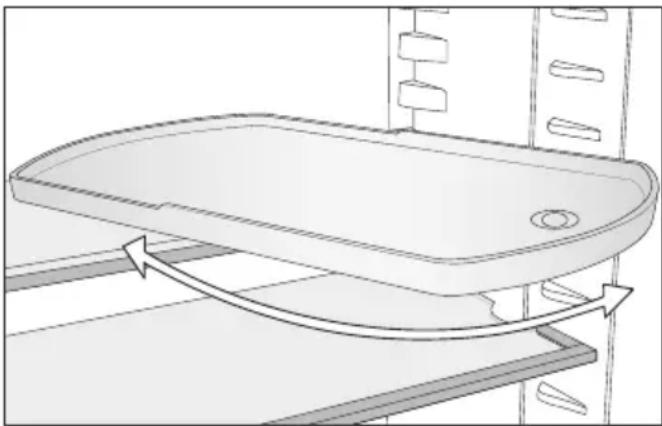
The pivotable glass shelf can be turned 180^ clockwise, improving access to the food placed at the back.
natural_image
Diagram of a bathroom sink with directional arrows indicating flow or movement (no text or symbols)⚠️ Danger of injury from dropping the glass shelf.
The pivotable glass shelf can come out when removing the adjustable shelf, causing the glass shelf to drop out of the tray and break.
Keep hold of the pivotable glass shelf when removing the adjustable shelf.
You can move the adjustable shelf with pivotable glass shelf as you wish.
Cleaning accessories by hand or in the dishwasher
The following components must be cleaned by hand only:
- The plastic parts of the adjustable shelf with pivotable glass shelf (Flexi-Tray)
The following components are dish-washer-safe:
⚠️ Risk of damage due to high dishwasher temperatures.
Parts of the refrigeration appliance may become unusable, e.g. deform, if they are washed in the dishwasher at more than 55 °C.
For dishwasher-safe components, always select dishwasher programmes with a maximum temperature of 55^ C.
Contact with natural dyes from carrots, tomatoes and ketchup, etc., may discolour the plastic parts in the dish-washer. This discolouration does not affect the stability of the parts.
- The glass shelves (without trim)
en - Adjustable shelf with pivotable glass shelf – Flexi-Tray
Dismantling the adjustable shelf with pivotable glass shelf (FlexiTray)
■ Place the adjustable shelf with pivot-able glass shelf on a worktop covered with a soft material (e.g. a tea towel).
natural_image
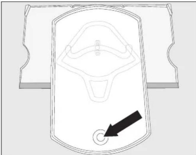
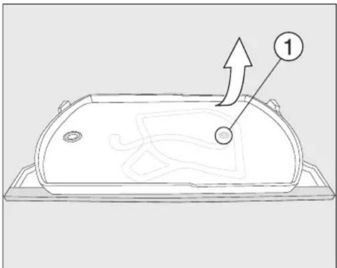
Technical line drawing of a mechanical component with a black arrow pointing to a circular hole (no text or symbols)■ Bring the tray to the front. Use the opening to lift the glass shelf from underneath and remove it.
■ Move the tray back to its original position resting on the adjustable shelf.
The tray can only be detached from the adjustable shelf once it has been returned to its original position and is resting on the adjustable shelf. The fastener must be sitting in the circular recess at the end of the runner guide ①.
text_image
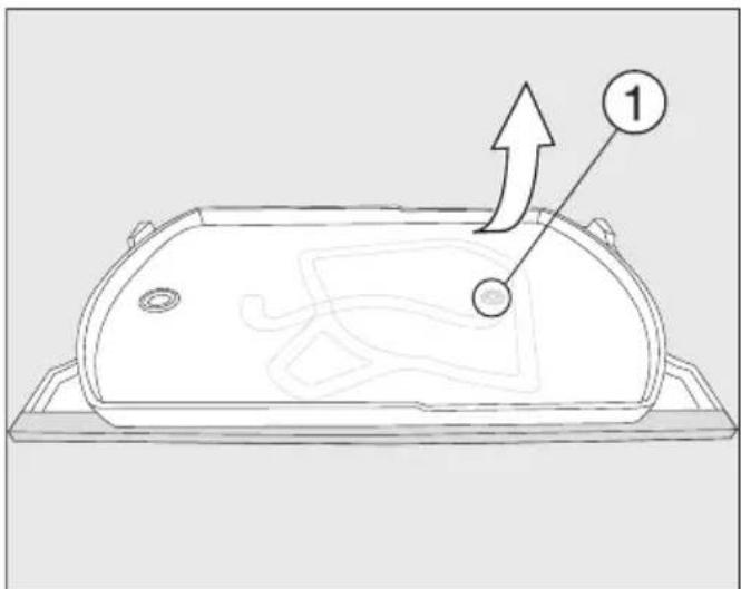
Diagram of a device casing with labeled component '1' and directional arrow indicating motion or movement■ Take a firm hold of the top right of the bottom adjustable shelf and pull the tray firmly off the adjustable shelf.
The fastener on the tray comes loose from the circular recess at the end of the runner guide ①.
You can now dismantle all the parts and clean them.
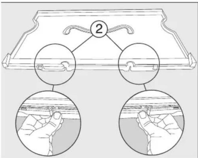
Underneath the plastic shelf, there is a glass panel which is held in place with retainers ② on the outer edge of the adjustable shelf.
The glass panel can also be removed for cleaning as described below:
■ Move the shelf so that the stainless steel trim is at the back and the front edge hangs over the worktop slightly.
en - Adjustable shelf with pivotable glass shelf – Flexi-Tray
text_image
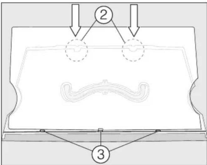
2■ Release the retainers ② and lift the shelf up.
The glass panel comes loose. Both parts can now be cleaned.
Assembling the adjustable shelf with pivotable glass shelf (FlexiTray)
■ Put the plastic adjustable shelf down on the worktop so that the recess is at the top and the stainless steel trim is at the front.
text_image
Technical diagram showing a mechanical assembly with labeled components and directional arrows indicating flow or movement.■ Place the glass panel in the grooves ③ and then secure it in the retainers ②.
■ Turn over the shelf so that the plastic surface is facing upwards.
natural_image
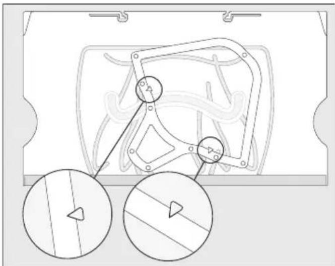
Technical diagram of a mechanical component with two circular inset views showing internal features (no text or labels)■ Place the frame on the adjustable shelf so that the arrows on the adjustable shelf line up with the recesses on the frame.

text_image
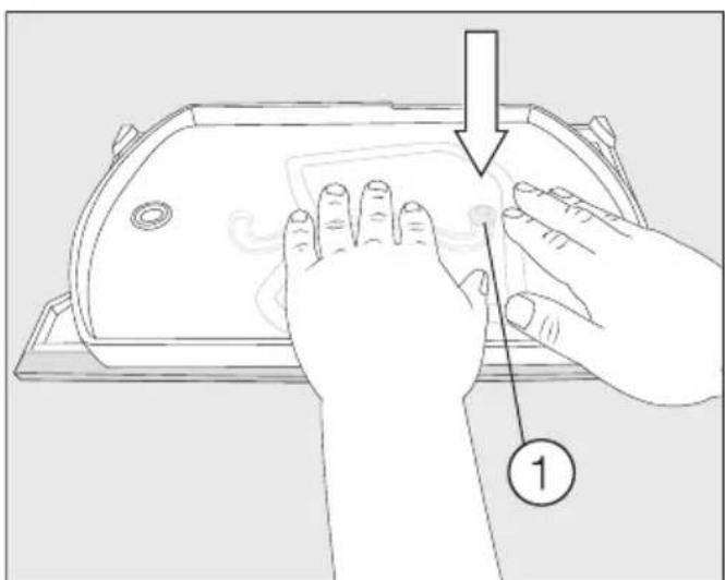
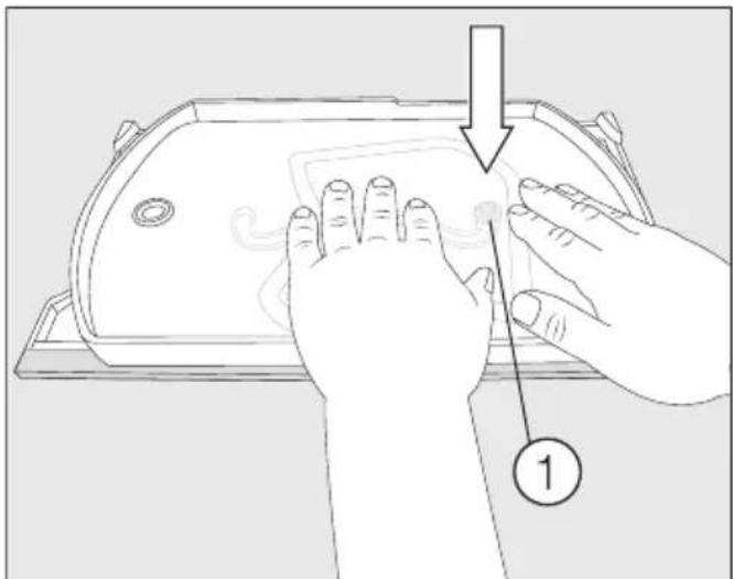
Diagram showing hand positioning on a device with labeled step 1■ Take hold of the tray with the fastener facing downwards and push the fastener firmly into the circular recess at the end of the runner guide ①.
■ Place the glass shelf in the tray.
Colocar la balda con base giratoria (FlexiTray)
natural_image
Diagram of a bathtub with directional arrows indicating flow or movement (no text or symbols)natural_image
Diagram of a device with a circular button and a black arrow pointing to it (no text or symbols present)text_image
Technical diagram of a device casing with labeled component '1' and directional arrow indicating motion or movement.text_image
Technical diagram showing a mechanical component with labeled parts and directional arrows indicating flow or assembly.natural_image
Technical line drawing of a mechanical component with two circular inset views showing internal features (no text or symbols)text_image
Diagram showing hands cleaning a device with a numbered step labeled '1'natural_image
Diagram of a bathtub with arrows indicating flow or movement, no text or symbols presentnatural_image
Diagram of a vehicle door with a black arrow pointing to the bottom-right corner (no text or symbols)text_image
Technical diagram of a device casing with labeled component '1' and directional arrow indicating motion or movement.text_image
Technical diagram showing a mechanical component with labeled parts and directional arrows indicating assembly or flow.natural_image
Technical line drawing of a mechanical component with two circular inset views showing internal features (no text or symbols)text_image
Diagram showing hand positioning on a device with labeled step 1natural_image
Diagram of a bathtub with airflow arrows indicating movement or flow direction (no text or symbols)natural_image
Diagram of a vehicle door with a black arrow pointing to the bottom-right corner (no text or symbols)text_image
Diagram of a device casing with labeled component '1' and directional arrow indicating motion or movementtext_image
Technical diagram showing a mechanical assembly with labeled components and directional arrows indicating flow or movement.natural_image
Technical diagram of a mechanical assembly with two circular inset views showing internal components (no text or labels)text_image
Diagram showing hands operating a device with a numbered step labeled '1'natural_image
Diagram of a bathroom sink with directional arrows indicating flow or movement (no text or symbols)natural_image
Diagram of a device casing with a circular button and an arrow pointing to it (no text or symbols)text_image
Diagram of a device casing with labeled component '1' and directional arrow indicating motion or movementtext_image
Technical diagram showing a mechanical assembly with labeled components and directional arrows indicating flow or movement.natural_image
Technical line drawing of a mechanical component with two circular inset views showing internal features (no text or symbols)text_image
Diagram showing hands cleaning a device with labeled step 1 and directional arrownatural_image
Diagram of a bathroom sink with directional arrows indicating flow or movement (no text or symbols)natural_image
Diagram of a device casing with a black arrow pointing to a circular button (no text or symbols)■ Okrenite pladanj prema naprijed. Podignite staklenu policu odozdo kroz otvor i uklonite staklenu policu.
■ Ponovno okrenite pladanj natrag u njegov početni položaj na površini za odlaganje.
Pladanj možete osloboditi s površine za odlaganje samo kada je pladanj okrenut u svoj početni položaj na površini za odlaganje. Spojna tipka mora biti u okruglom krajnjem položaju vodilice kretanja ①.
text_image
Diagram of a device casing with labeled component '1' and directional arrow indicating motion or movement■ Donju površinu za odlaganje čvrsto držite gore desno te pladanj snažno povucite s površine za odlaganje.
text_image
Technical diagram showing a mechanical assembly with labeled components and directional arrows indicating flow or movement.■ Prvo postavite staklenu policu u uto-re ③ te je zatim pričvrstite u zasu-ne ②.
■ Okrenite površinu za odlaganje tako da je plastična površina okrenuta prema gore.

natural_image
Technical diagram of a mechanical assembly with two circular inset views showing internal components (no text or labels)■ Postavite rubni okvir na površinu za odlaganje tako da otisnuti vrhovi strelica na površini za odlaganje odgovaraju vrhovima upusta na okviru.
text_image
Diagram showing hand positioning on a device with labeled step 1 and directional arrow■ Uzmite pladanj sa spojnom tipkom usmjerenom prema dolje te spojnu tipku snažno pritisnite u okrugli krajnji položaj vodilice kretanja ①.
■ Položite staklenu policu u pladanj.
natural_image
Diagram of a bathtub with directional arrows indicating flow or movement (no text or symbols)natural_image
Diagram of a vehicle door with a black arrow pointing to the bottom-right corner (no text or symbols)text_image
Technical diagram of a device casing with labeled component '1' and directional arrow indicating motion or movement.text_image
Technical diagram showing a mechanical assembly with labeled components and directional arrows indicating flow or movement.natural_image
Technical diagram of a mechanical assembly with two circular inset views showing internal components (no text or labels)text_image
Diagram showing hands operating a device with a numbered step labeled '1' pointing to the screen area.natural_image
Line drawing of a bathroom sink with directional arrows indicating flow or movement (no text or symbols)natural_image
Diagram of a device casing with a circular button and an arrow pointing to it (no text or symbols)text_image
Diagram of a device casing with labeled component '1' and directional arrow indicating motion or movementtext_image
Technical diagram showing a mechanical component with labeled parts and directional arrows indicating assembly or flow.natural_image
Technical diagram of a mechanical component with two circular inset views showing internal features (no text or labels)text_image
Diagram showing hands operating a device with a numbered step indicator pointing to the screen area.natural_image
Diagram of a bathroom sink with directional arrows indicating flow or movement (no text or symbols)natural_image
Diagram of a device casing with a black arrow pointing to a circular button (no text or symbols)text_image
Technical diagram of a device casing with labeled component '1' and directional arrow indicating motion or movement.text_image
Technical diagram showing a mechanical assembly with labeled components and directional arrows indicating flow or movement.natural_image
Technical diagram of a mechanical component with two circular inset views showing internal features (no text or labels)text_image
Diagram showing hand positioning on a device with labeled step 1natural_image
Diagram of a bathroom sink with directional arrows indicating flow or movement (no text or symbols)natural_image
Diagram of a vehicle door with a black arrow pointing to the bottom-right corner (no text or symbols)text_image
Diagram of a device casing with labeled component '1' and directional arrow indicating motion or movement.text_image
Technical diagram showing a mechanical component with labeled parts and directional arrows indicating assembly or flow.natural_image
Technical line drawing of a mechanical component with two circular inset views showing internal features (no text or symbols)text_image
Diagram showing hands cleaning a device with a numbered step labeled '1'natural_image
Diagram of a bathtub with airflow arrows indicating movement or flow direction (no text or symbols)natural_image
Diagram of a device casing with a circular button and an arrow pointing to it (no text or symbols)text_image
Diagram of a device casing with labeled component '1' and directional arrow indicating motion or movementtext_image
Technical diagram showing a mechanical assembly with labeled components and directional arrows indicating flow or movement.natural_image
Technical diagram of a mechanical component with two circular inset views showing internal features (no text or labels)text_image
Diagram showing hand positioning on a device with labeled step 1 and directional arrownatural_image
Diagram of a bathtub with directional arrows indicating flow or movement (no text or symbols)⚠️ Fare for skade dersom glass-hyllen faller ut.
natural_image
Diagram of a device casing with a circular button and an arrow pointing to it (no text or symbols present)text_image
Diagram of a device casing with labeled component '1' and directional arrow indicating motion or movementtext_image
Technical diagram showing a mechanical component with labeled parts and directional arrows indicating flow or assembly.natural_image
Technical diagram of a mechanical component with two circular inset views showing internal features (no text or labels)text_image
Diagram showing hands operating a device with a numbered step labeled '1'natural_image
Line drawing of a bathtub with arrows indicating flow or movement, no text or symbols presentnatural_image
Diagram of a device casing with a circular button and an arrow pointing to it (no text or symbols)text_image
Diagram of a device casing with labeled component '1' and directional arrow indicating motion or movementtext_image
Technical diagram showing a mechanical component with labeled parts and directional arrows indicating assembly or flow.natural_image
Technical diagram of a mechanical component with two circular inset views showing internal features (no text or labels)text_image
Diagram showing hands operating a device with a numbered step indicator pointing to the screen area.natural_image
Diagram of a bathroom sink with directional arrows indicating flow or movement (no text or symbols)natural_image
Technical line drawing of a mechanical component with a black arrow pointing to a circular button (no text or symbols)text_image
Diagram of a device casing with labeled component '1' and directional arrow indicating motion or movementtext_image
Technical diagram showing a mechanical assembly with labeled components and directional arrows indicating flow or movement.natural_image
Technical diagram of a mechanical assembly with two circular inset views showing internal components (no text or labels)text_image
Diagram showing hand positioning on a device with labeled step 1 and directional arrownatural_image
Line drawing of a bathroom sink with directional arrows indicating flow or movement (no text or symbols)natural_image
Diagram of a device with a circular button and a black arrow pointing to it (no text or symbols present)text_image
Technical diagram of a device casing with labeled component '1' and directional arrow indicating motion or movement.text_image
Technical diagram showing a mechanical component with labeled parts and directional arrows indicating assembly or flow.natural_image
Technical line drawing of a mechanical component with two circular inset views showing internal features (no text or symbols)text_image
Diagram showing hands cleaning a device with a numbered step labeled '1'natural_image
Diagram of a bathroom sink with directional arrows indicating flow or movement (no text or symbols)natural_image
Diagram of a device casing with a black arrow pointing to a circular button (no text or symbols)text_image
Diagram of a device casing with labeled component '1' and directional arrow indicating motion or movementtext_image
Technical diagram showing a mechanical assembly with labeled components and directional arrows indicating flow or movement.natural_image
Technical diagram of a mechanical component with two circular inset views showing internal features (no text or labels)text_image
Diagram showing hands cleaning a device with a numbered step labeled '1'natural_image
Line drawing of a bathtub with arrows indicating flow or movement, no text or symbols presentnatural_image
Diagram of a device casing with a circular button and an arrow pointing to it (no text or symbols present)text_image
Diagram of a device casing with labeled component '1' and directional arrow indicating motion or movement■ Spodnú odkladaciu plochu držte pevne vpravo hore a tácku z nej silou stiahnite.
text_image
Technical diagram showing a mechanical assembly with labeled components and directional arrows indicating flow or movement.Najprv nasadte sklenenú dosku do drážok ③ a potom ju zaklapnite do západiek ②.
natural_image
Technical diagram of a mechanical assembly with two circular inset views showing internal components (no text or labels)text_image
Diagram showing hands installing or adjusting a device component with a numbered callout indicating step 1natural_image
Line drawing of a bathtub with arrows indicating flow or movement, no text or symbols present⚠️ Nevarnost poškodbe zaradi padca steklenega dna.
natural_image
Diagram of a vehicle door with a black arrow pointing to the bottom-right corner (no text or symbols)text_image
Diagram of a device casing with labeled component '1' and directional arrow indicating motion or movement.■ Spodnjo polico držite zgoraj desno in močno povlecite pladenj s police.
text_image
Technical diagram showing a mechanical component with labeled parts and directional arrows indicating flow or movement.■ Stekleno ploščo najprej vstavite v utore ③ in jo nato potisnite v nastavka ②, tako da se zaskoči.
■ Polico obrnite, tako da je plastična površina obrnjena navzgor.

natural_image
Technical diagram of a mechanical component with two circular inset views showing internal features (no text or labels)■ Tekalni okvir položite na polico tako, da se konice puščic, vtisnjene v polico, prilegajo v koničaste vrzeli na okvirju.
text_image
Diagram showing hand positioning on a device with labeled step 1natural_image
Diagram of a bathroom sink with directional arrows indicating flow or movement (no text or symbols)natural_image
Diagram of a door handle with a black arrow pointing to the center (no text or symbols)■ Okrenite tacnu ka napred. Podignite staklenu policu odozdo kroz otvor i izvadite staklenu policu.
■ Ponovo okrenite tacnu i vratite je u njen početni položaj na policu za odlaganje.
Tacnu možete da uklonite sa police za odlaganje kada je okrenete na njen početni položaj na policu za odlaganje. Dugme za povezivanje se mora nalaziti u okruglom krajnjem položaju vođice ①.

text_image
Diagram of a device casing with labeled component '1' and directional arrow indicating motion or movement- Čvrsto držite donju policu za odlaganje sa gornje desne strane i snažno povucite tacnu sa police za odlaganje.
text_image
Technical diagram showing a mechanical assembly with labeled components and directional arrows indicating flow or movement.natural_image
Technical diagram of a mechanical component with two circular inset views showing internal features (no text or labels)■ Stavite okvir na policu za odlaganje tako da se vrhovi strelica utisnuti na polici za odlaganje uklapaju u oštre ispuste na okviru.

text_image
Diagram showing hands cleaning a device with labeled step 1 and directional arrow■ Uzmite ležište tako da je dugme za povezivanje okrenuto nadole i snažno pritisnite dugme za povezivanje u okrugli krajnji položaj vodice cevi ①.
■ Stavite staklenu policu u podmetač.