
WT-1040S - Heating Ravanson - Free user manual and instructions
Find the device manual for free WT-1040S Ravanson in PDF.


| Product Type | Stand Fan |
| Model | WT-1040S / WT-1040SB |
| Brand | Ravanson |
| Power Supply | 220–240 V ~ 50/60 Hz |
| Rated Power Input | 45 W |
| Max Airflow | 74.37 m³/min |
| Service Value | 1.84 (m³/min)/W |
| Standby Power Consumption | 0.44 W |
| Sound Power Level | 53.61 dB(A) |
| Max Air Velocity | 2.27 m/s |
| Speed Settings | 3 (1 – slowest, 3 – fastest) |
| Oscillation | Yes, push-button on drive unit |
| Tilt Feature | Yes, manually adjustable |
| Blade Nut Thread | Left-hand thread (anticlockwise to tighten) |
| Protective Guard | Yes, front and rear grids |
| Safety Features | Do not use with damaged cord or blades; keep away from water; children under 8 supervised |
| Cleaning | Wipe with moist cloth and neutral detergent; no solvents |
| Climate Class | T |
| Measurement Standard | IEC 60879 |
| Contact | RAVANSON Ltd., ul. Mazowiecka 6, 09-100 Płońsk, Poland |
Frequently Asked Questions - WT-1040S Ravanson
User questions about WT-1040S Ravanson
0 question about this device. Answer the ones you know or ask your own.
Ask a new question about this device
Download the instructions for your Heating in PDF format for free! Find your manual WT-1040S - Ravanson and take your electronic device back in hand. On this page are published all the documents necessary for the use of your device. WT-1040S by Ravanson.
USER MANUAL WT-1040S Ravanson
ENG User's manual Fan
natural_image
Two identical electric fans standing upright, showing fan blades and stand (no text or symbols visible)MODEL:
WT-1040S/WT1040SB
Producent:
Ravanson®
Rys. 2
natural_image
Technical line drawing of a vertical cylindrical device with internal components and directional arrows indicating motion (no text or symbols)Rys 4
OBSŁUGA
UWAGA!
natural_image
Technical diagram of a mechanical device with a grid-patterned side panel and directional arrows (no text or symbols)Rys. 5a
Rys. 5b
natural_image
Diagram of a mechanical device with rotating components and a grid-patterned component, showing rotational motion arrows (no text or symbols)CZYSZCZENIE I KONSERWACJA
Before first use, always read the safety instructions and warnings included in this guide.
Failure to observe the below mentioned safety warnings and safety guidelines for may cause to electric shock, fire and/or serious injuries
Keep safety instructions and warnings at hand for future reference
GENERAL SAFETY GUIDELINESS
This appliance is not intended for use by children under the age of 8 or other persons, without assistance or supervision, if their physical, sensory or mental capabilities prevent them from using it safely or by persons without experience and knowledge on the use thereof. People using this product must understand the risks related to the use of the appliance. Do not allow children to use the appliance as a toy. Cleaning and maintenance by children without supervision is not allowed.
Children are not aware of dangers that may arise during the use of electric devices. Keep the appliance and corresponding cord out of the reach of children under the age of 8.
Children should be supervised to ensure that they do not play with the appliance.
Do not operate the appliance with a damaged cord. Damaged power cord must be replaced by manufacturer, authorized service centre or other qualified persons in order to avoid risk.
The plug must fit the socket.
The plug must not be modified in any way.
Do not allow the power cord to touch sharp edges or hot surfaces.
Damaged cord poses a risk of electric shock.
Do not place the appliance on hot surfaces.
Do not use outside. Do not expose to rain. Protect against humidity.
Do not operate with wet hands.
During operation keep clothing, long hair away from the moving parts of the appliance.
Do not plug the device in unless it is fully assembled.
Do not use the device with a broken or damaged blades.
Do not remove any parts of the housing.
Do not use the device in the immediate vicinity of a bathtub, shower or swimming pool.
Prevent the cord and plug from any contact with water or moisture.
Do not spray any liquid on the device.
Unplug the device holding the plug; do not pull the cord.
Unplug the device if it is to be moved or is not going to be used for a longer time.
Do not use the device with the protection grid removed.
Transport in an original package protecting from mechanical damages.
The appliance must be repaired by a qualified person using only original spare parts.
Despite operating the unit in accordance with its intended use and in accordance with all safety guidelines, it is impossible to eliminate all residual risk factors.
The appliance is intended for home use only.
The appliance should only be used for private use, as intended for the appliance. This appliance is not intended for commercial use.
Before assembly and disassembly of the sieve, always make sure that the juicer is disconnected from its power source.
Do not cover the fan protection grid.
Do not put anything into the protection grid when the fan is on.
NOTE! The device is not designed to work with external timers or a separate remote control system.
It is recommended to connect the device to the power supply network equipped with a residual current device (RCD) with a switch-off current of 30mA or less.
Parts
Please check the fan is complete after you open the packaging. Check if the components are not damaged.

Assembly
- Screw the blade cover 10 to the front grid 6 (see Figure 1)
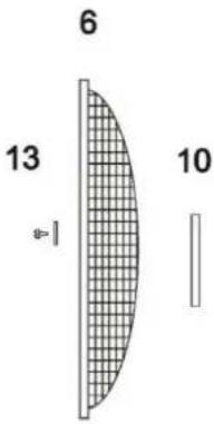
Fig 1
- Assembly the fan as shown in Figure 2
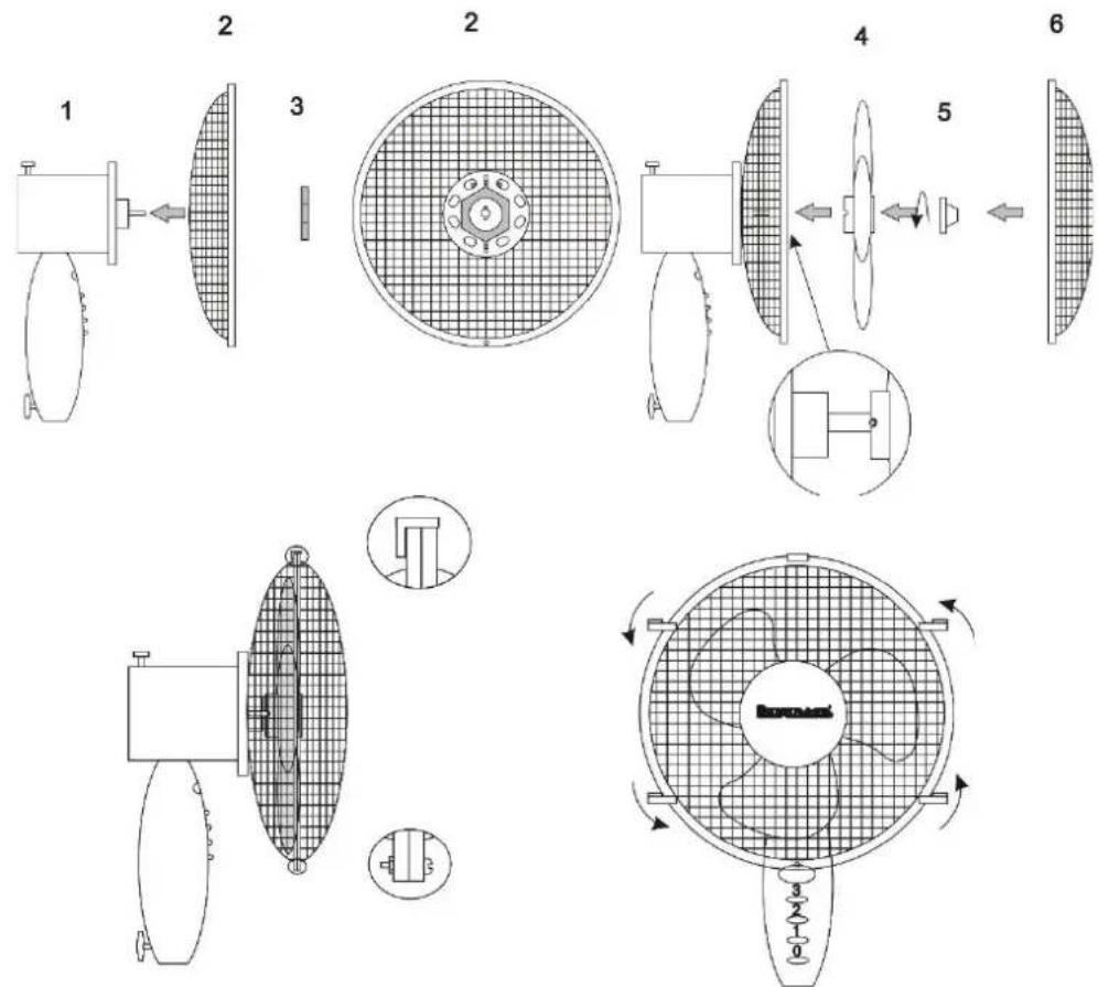
Fig 2
Attention! Screw blade nut onto the screw, turning anticlockwise (left-hand thread).
- Assembly the fan column as shown in Figure 3
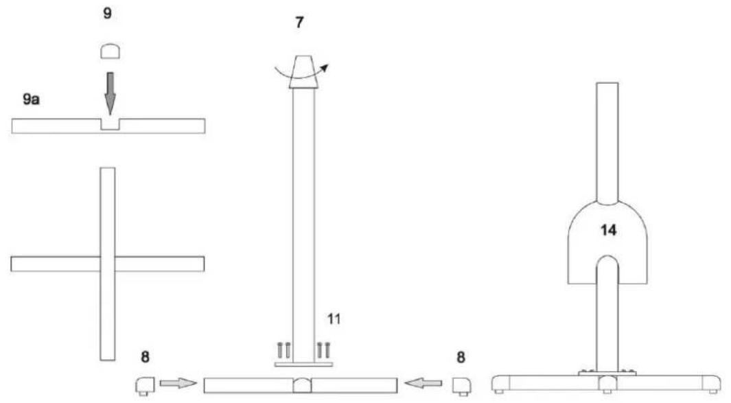
Fig 3
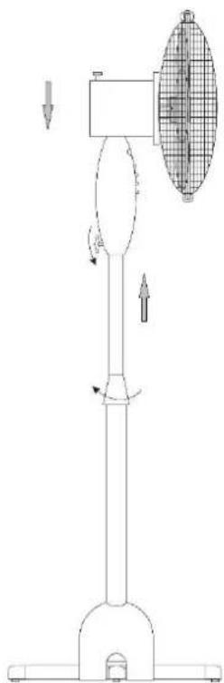
4. Install the fan on the column (Figure 4)
natural_image
Technical line drawing of a vertical support structure with directional arrows indicating motion (no text or symbols)Fig 4
Attention! Make sure that the power source to which the appliance is to be connected is accordant with the parameters specified on the rating plate.
Attention! Before every use, inspect the device for any signs of mechanical damage. Inspect the power cord.
If the power cord is damaged, do not plug the device in.
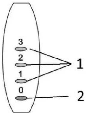
- Speed control buttons 1 to 3
- OFF
flowchart
graph TD
    A["0"] --> B["1"]
    C["1"] --> B["1"]
    D["2"] --> B["1"]
    E["3"] --> B["1"]
Fan speed can be set from 1 (slowest) to 3 (fastest). "0" position – switching the fan off.
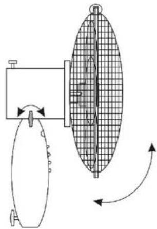
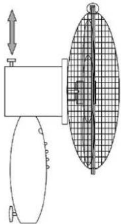
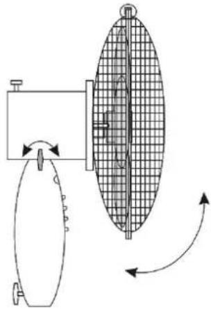
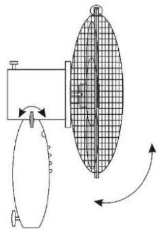
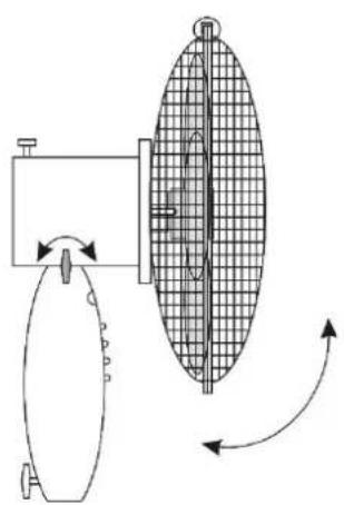
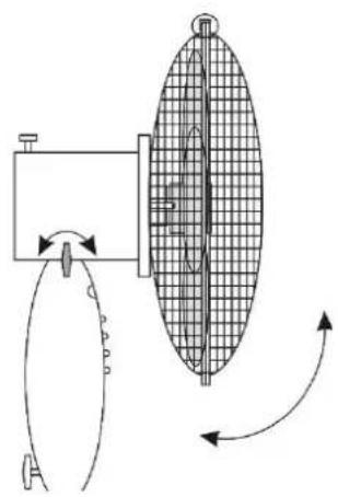
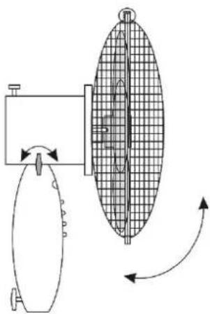
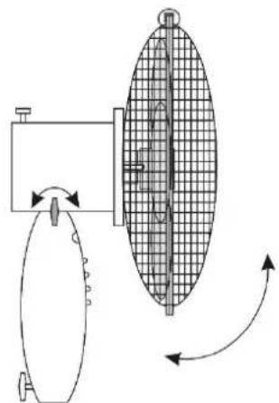
The fan is equipped with a rotational mechanism. Automatic rotation of the fan round its vertical axis is switched on by the button on the drive unit housing (1). See Fig. 5A.
This function is switched on by pressing the button. To disable device rotation, pull the button out.
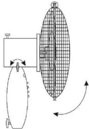
The fan head can be tilted in a horizontal axis by aslight inflection/deflection of the drive unit. See Fig. 5B.
natural_image
Technical diagram of a mechanical device with a grid-patterned component and directional arrows (no text or symbols)Fig 5a
Fig 5b
natural_image
Diagram of a mechanical device with internal components and directional arrows indicating motion (no text or symbols)Cleaning and care
Before starting the maintenance, ensure the fan is unplugged.
Clean the fan with moist (never wet) cloth with a neutral detergent. Do not use petrol or other solvents.
Transportation and storage
Before putting the device away, wait until it cools down. Keep and store in a package protecting from humidity and mechanical damages.
Troubleshooting
If the fan does not start, check the power supply in the mains. Repairs must be carried out solely by the authorised personnel.
Technical parameters
WT-1040S WT-1040SB
Voltage 220–240 V 220 – 240 V
Frequency 50/60 Hz 50/60 Hz
Rated power 45 W 45 W
Climate class T T
The manufacturer reserves the right to introduce technical modifications!
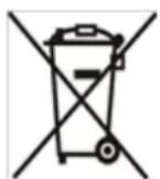
The symbol presented below indicates that the used equipment cannot be placed together with other household waste. The user is obliged to bring this item to the waste electrical and electronic equipment collection point where a suitable system is created to allow safe disposal of these items.
Dangerous components present in electrical and electronic equipment have negative
consequences for the environment and human health therefore correct handling of the equipment is very important. Certain substances which may adversely affect the environment over the life of the product and after use have been limited in this device.
| Description | Symbol | Value | Unit |
| Maximum fan flow rate | [F] | 74,37 | m^3/min |
| Fan Power input | [P] | 40,40 | W |
| Sernice value | [SV] | 1,84 | (m^3/min)/W |
| Standy power consumption | [P_SB] | 0,44 | W |
| Fan sound Power level | [L_WA] | 53,61 | dB(A) |
| Maximum air velocity | [c] | 2,27 | m/s |
| Measurement standard for service value | IEC 60879 | ||
| Contact details obtaining more information | RAVANSON Ltd., Sp. z o.o.ul. Mazowiecka 6, 09-100 Płońsk, Poland | ||
DE

natural_image
Technical line drawing of a vertical mechanical device with directional arrows indicating motion or force (no text or symbols)Abb. 4
natural_image
Pure mechanical diagram showing a lever and a grid-patterned component without any text or symbolsAbb. 5a
Abb. 5b
natural_image
Diagram of a mechanical device with a grid-patterned component and directional arrows indicating motion (no text or symbols)Instandhaltung
natural_image
Technical line drawing of a vertical cylindrical device with directional arrows indicating motion or force (no text or symbols)Мал. 4
ОБСЛУГОВУВАННЯ
УВАГА!
natural_image
Diagram of a mechanical device with a grid-patterned component and directional arrows (no text or symbols)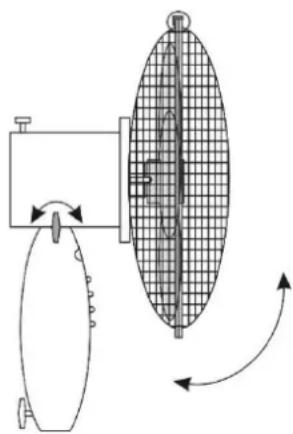
natural_image
Diagram of a mechanical device with internal grid structure and directional arrows (no text or symbols)Мал. 5а
Мал. 5b
natural_image
Technical line drawing of a vertical industrial device with directional arrows indicating motion (no text or symbols)Obr. 4
natural_image
Technical diagram of a mechanical device with a grid-patterned component and directional arrows (no text or symbols)Obr. 5A Obr. 5B
natural_image
Diagram of a mechanical device with a grid-patterned component and directional arrows indicating motion (no text or symbols)Údržba:
natural_image
Diagram of a vertical pole-mounted device with directional arrows indicating motion, no text or symbols presentObr. 4
natural_image
Technical diagram showing a mechanical assembly with a vertical component and a grid-patterned oval component (no text or symbols)Obr. 5A
Obr. 5B
natural_image
Diagram of a mechanical device with internal grid structure and directional arrows indicating motion (no text or symbols)Údržba:
natural_image
Technical line drawing of a vertical mechanical device with directional arrows indicating motion (no text or symbols)Sl.4
Pozor! Preverite, ali vir napajanja, na katerega želite priključiti napravo, ustreza parametrom, navedenim na podatkovni ploščici.
natural_image
Pure mechanical diagram showing a lever and grid-patterned component without any text or symbolsSI.5A
natural_image
Diagram of a mechanical device with rotating components and a grid-patterned component, showing directional arrows (no text or symbols)Sl.5B
Vzdrževanje
natural_image
Technical line drawing of a vertical mechanical device with directional arrows indicating motion (no text or symbols)pav.4
natural_image
Technical diagram of a mechanical device with a grid-patterned oval component and directional arrows (no text or symbols)pav.5A pav.5b
natural_image
Diagram of a mechanical device with internal grid structure and directional arrows indicating motion (no text or symbols)Priežiūra:
natural_image
Technical line drawing of a vertical cylindrical device with internal components and directional arrows indicating motion (no text or symbols)joonis 4
natural_image
Technical diagram of a mechanical device with a grid-patterned internal structure and directional arrows (no text or symbols)joonis 5A joonis 5A
natural_image
Diagram of a mechanical device with internal grid structure and directional arrows indicating motion (no text or symbols)Hooldus:
natural_image
Technical line drawing of a vertical mechanical device with directional arrows indicating motion (no text or symbols)(Zīm. 4)
Apkalpošana
Uzmanību!
natural_image
Technical diagram showing a mechanical assembly with a vertical grid structure and an upward arrow, no text or symbols present.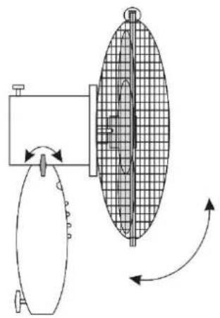
natural_image
Diagram of a mechanical device with internal components and directional arrows indicating motion (no text or symbols)TİRİŞANA UN KONSERVÄCIJA
natural_image
Technical line drawing of a vertical mechanical device with directional arrows indicating motion (no text or symbols)(4. ábra)
HASZNÁLAT
FIGYELEM!
natural_image
Pure mechanical diagram showing a rotating component and a grid-patterned oval structure (no text or symbols)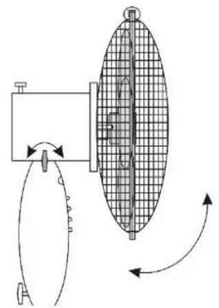
natural_image
Diagram of a mechanical device with rotating components and a grid-patterned component, showing directional arrows (no text or symbols)- Ravanson®
- OBSŁUGA
- UWAGA!
- CZYSZCZENIE I KONSERWACJA
- GENERAL SAFETY GUIDELINESS
- Do not cover the fan protection grid.
- Assembly
- Cleaning and care
- Transportation and storage
- Troubleshooting
- Technical parameters
- WT-1040S WT-1040SB
- DE
- Instandhaltung
- ОБСЛУГОВУВАННЯ
- УВАГА!
- Údržba:
- Vzdrževanje
- Priežiūra:
- Hooldus:
- Apkalpošana
- Uzmanību!
- TİRİŞANA UN KONSERVÄCIJA
- HASZNÁLAT
- FIGYELEM!
Brand : Ravanson
Model : WT-1040S
Category : Heating