
HB18 - Compressor Cocraft - Free user manual and instructions
Find the device manual for free HB18 Cocraft in PDF.


| Product Type | Pneumatic Nail Gun |
| Brand | Cocraft |
| Model | HB18 |
| Length | 245 mm |
| Height | 240 mm |
| Width | 56 mm |
| Weight | 1.3 kg |
| Magazine Capacity | 100 nails |
| Working Pressure Range | 4–7 bar |
| Nail Size Range | 10–50 mm |
| Air Inlet | Quick coupling |
| Impact Depth Adjustment | Rotary knob, tool-free |
| Safety Lock | Yes, automatic safety catch |
| Trigger Type | Safety trigger with sequential firing |
| Lubrication | Pneumatic tool oil (few drops in air inlet) |
| Included Accessories | Allen keys, rubber guard |
| Compliance | CE, Machinery Directive 2006/42/EC |
| Power Source | Compressed air |
| Maximum Working Pressure | 7 bar |
Frequently Asked Questions - HB18 Cocraft
User questions about HB18 Cocraft
0 question about this device. Answer the ones you know or ask your own.
Ask a new question about this device
Download the instructions for your Compressor in PDF format for free! Find your manual HB18 - Cocraft and take your electronic device back in hand. On this page are published all the documents necessary for the use of your device. HB18 by Cocraft.
USER MANUAL HB18 Cocraft
ADJUSTABLE IMPACT DEPTH
SPIKPISTOL T-DYCKERT SPIKERPISTOL NAULAIN T-DYCKERT STAUCHKOPFNAGLER

Important:
Read the entire instruction manual carefully and make sure that you fully understand it before you use the equipment. Keep the manual for future reference.
Viktig information:
Original instructions
Bruksanvisning i original
Originalbruksanvisning
Please read the entire instruction manual before using the product and save it for future reference. We reserve the right for any errors in text or images and any necessary changes made to technical data. If you have any questions regarding technical problems please contact Customer Services.
Safety

Warning:
- Never hold your hand or any other part of your body close to the muzzle of the nail gun when the gun is connected with the compressed air hose.
- Never point the tool at any person or animal.
- Do not play with the tool.
- Never depress the trigger if the nose of the tool is not pointed at the workpiece.
• Always handle the tool with care. - Never depress the trigger or release the safety catch while you are loading the tool.
- Use the tool solely for the purpose for which it is intended.
- Never use the tool in such a way that it is pointed at yourself or someone else in the work area.
- Do not use the tool as a hammer.
- Carry the tool by the handle, not by the air hose.
- Never carry the tool with the trigger depressed.
- Never modify the tool in departure from the original design.
• Always keep in mind that misuse or faulty handling of this tool could injure yourself and others. - Never fasten or tape the safety catch and/or trigger in activated position.
- Never leave a tool unattended when it is connected to the air line.
- Do not use this tool if it does not bear a legible warning decal.
- Do not continue using a tool that is leaking air or is not working properly. Contact our Customer Service for servicing.
- When using the tool, hold it in such a way that no injury to the head or body could result should a fall in pressure or hard spots on the workpiece cause the recoil force to increase.
- Do not nail too close to the edge of a workpiece. The nail could pass through the workpiece and cause damage.
- Disconnect the tool from the compressed air for transporting.
- Check frequently that both the trigger and the safety catch are working properly.
- Do not take apart any part of the tool.
- Make no provisional repairs.
• Always have authorized personnel do servicing and repairs, and only with original spare parts. - Avoid weakening the housing by engraving or scratching it, etc.
- Always make a note of where the electric cable goes into walls, floors or ceilings before you begin to use the nail gun.
- The compressed air fitting for the nail gun must be of the quick-coupling type. The connecting piece on the tool may not have a rear valve so that some air remains under pressure when the nail gun has been disconnected.
Compressed air feed and connections

Warning:
To prevent accidents due to unintended firing, the operator should always disconnect the compressed air:
- Before adjusting
- When cleaning the nail gun
- When removing a stuck nail
- When the tool is not being used
- When moving the tool to another work area

Warning:
- Use only compressed air in pneumatically driven tools. Never use acid or flammable gases to drive the tool since they carry the risk of explosion.
- The compressor capacity must be sufficient to ensure an adequate air pressure and flow for the intended use. A fall in pressure in the system can reduce the tool's thrust. See Specifications for setting the right pressure for the tool.
- The compressed air lines should be mounted on an incline, with the highest point closest to the compressor. An easily accessed water separator should be installed at the lowest points. The water separator should be emptied at least once a day, or more often if needed. Dirt and water in the compressed air lines are one of many causes of wear in pneumatically actuate tools.
- The tool connection fittings should be equipped with a reducing valve with water separator directly at the connection site. A filter helps to achieve maximum effect at minimum wear. The filter must have sufficient flow capacity for the intended mounting site or connecting point. The filter must be kept clean if it is to be able to deliver clean compressed air to the tool. See the manufacturer's instructions for proper filter care. A dirty or clogged filter will cause a fall in pressure, which reduces the nail gun's effectiveness.
- The pressure regulator must be adjustable from 0 to 7 bar.
- The air hoses must tolerate at least 10.5 bar working pressure or 150% of the maximum air pressure the system can create. The meter line should have a quick coupling for quick detachment from the nail gun's nipple.
- Make sure that the compressed air fed to the nail gun does not exceed the maximal permissible working pressure (7 bar). Initially set the meter pressure at the lowest recommended working pressure; See Specifications.
- Check that the nail gun is working properly by running function and safety checks for every job.

Warning:
To prevent serious eye injury from flying nails and/or slivers, the operator and others in the working area must be equipped with eye protection that covers both the front and the sides when loading, using or servicing the tool.
Glasses without eye protection on the side and facemasks do not give adequate protection.
Warning symbols on tool

Read the instructions for use.

The user and other persons in the work area must use protective glasses and hearing protection.
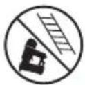
The tool should not be used on scaffolding or ladders. Do not use the nail gun if the fastening unit could shoot through something and hit someone on the other side.

The gun is equipped with a safety trigger.
Product description
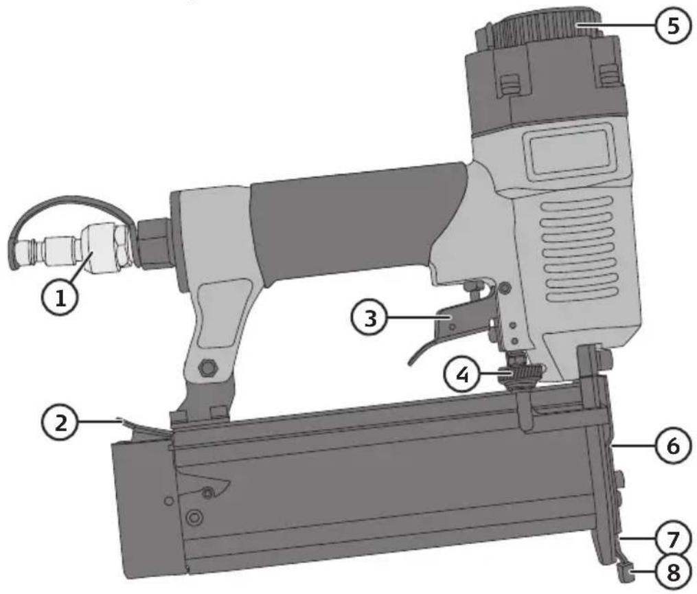
-
Air inlet coupling
-
Magazine lock
-
Trigger
-
Impact depth adjustment knob
-
Air outlet adjustment knob
-
Front plate
-
Safety lock
-
Rubber guard
Installation
Suggestion for installation
- The compressor used to drive the tool must be able to maintain a working pressure of at least 4 bar for the tool to work properly.
- Use quick-couplings to easily disconnect the tool and hose from the compressor.
- Make sure that the connected tool and hoses do not have a lower capacity than the compressor and that they are correctly fitted.
- If a pressure regulator is used it must be able to be set for a working pressure of 4–7 bar.
Lubrication
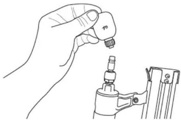
Note: Lubricate the tool with a few drops of oil in the air-line connection before using the tool for the first time.
- Disconnect the compressed air from the nail gun.
- Put 4–5 drops of oil in the air inlet.
Note: Do not use ordinary motor oil as it contains additives that will damage the tool. Oil for lubricating a pneumatic tool is available commercially. - Wipe away any oil that may come out of the air inlet when beginning to use the tool.
natural_image
Line drawing of a hand holding a small mechanical component, with a close-up view of its base (no text or symbols)Function and safety checks
- Disconnect the compressed air from the nail gun.
- Remove any nails from the magazine.
- Make sure that the safety lock moves freely up and down by pressing the tool against a work surface.
- Connect to the compressed air.
- Press the tool against the work surface. The tool must not fire.
- Take the tool away from the work surface, and make sure the safety lock returns to its position. Press the trigger in. The tool must not fire.
- Press the tool against the work surface, press the trigger. The tool should fire.
Loading
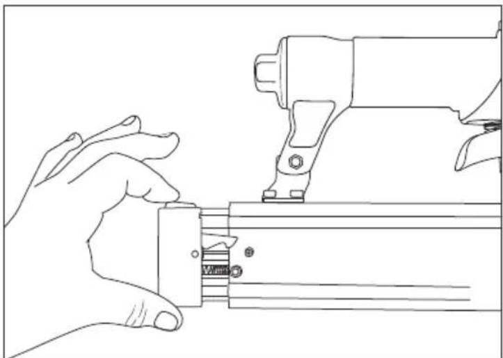
- Open the magazine by pressing the lock down and pulling it straight out.
natural_image
Line drawing of a hand holding a mechanical component with a tool, no text or symbols present-
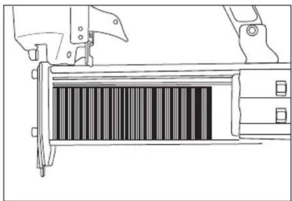
Place nails in the magazine, ensure that the tips point downward, and lie against the bottom of the magazine.
-
Shove the magazine back until the magazine lock clicks firmly in place.
natural_image
Technical line drawing of a mechanical assembly with a barcode bar inside (no text or symbols)Instructions for use
△ Important:
Always test-fire the nail gun on a scrap piece of the same material as the workpiece. Set the impact depth to the desired level using the adjustment knob.
- Hold the nail gun in a firm grip.
- Press the nail gun against the workpiece.
- Pull the trigger and release it after the gun has fired.
- Move the nail gun to the next firing position and repeat.
You can also keep the trigger held in and press the nail gun against the work surface to fire.
Setting the impact depth and impact force
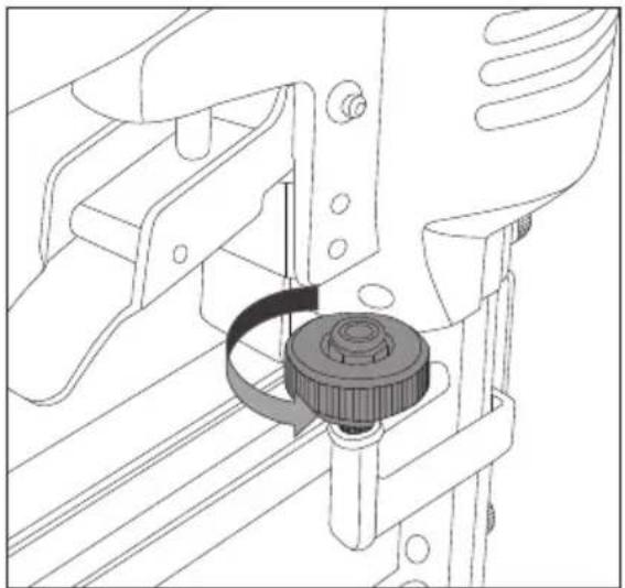
A. Adjusting the impact depth with the adjustment knob
natural_image
Technical line drawing of a mechanical assembly with a central gear mechanism (no text or symbols)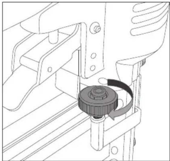
natural_image
Technical line drawing of a mechanical assembly with a gear and rotating component (no text or symbols)Turn the adjustment knob (4) anticlockwise to reduce the impact depth or clockwise to increase the impact depth.
The rubber guard (8) can be removed to increase the impact depth even more.
B. Adjusting the impact force with pressure regulator on air hose
If the nail has not been driven deep enough first check whether the impact depth adjustment knob (4) is set at the maximum nail depth. If it is at the maximum raise the air pressure by 0.5 bar increments and check with the nailing control after each increment. Do not exceed the max. working pressure (7 bar).
If the nail has been driven in too deep, reduce the air pressure by 0.5 bar at a time, checking the result each time. Do not go below the minimum recommended working pressure (4 bar).
Always work with the lowest possible working pressure. This minimizes the noise and vibration levels and the internal components of the nail gun will last longer.
Removing a nail that has become jammed
- Disconnect the air hose from the nail gun.
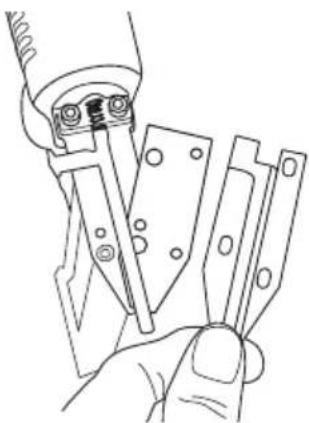
- Remove the magazine and dislodge the nail that has become stuck and/or remove the 3 screws which hold the front plate in place using the included Allen key.
- Remove both the outer and inner front plate.
- Remove the nail that has become stuck and then refit the front plate.
natural_image
Line drawing of a hand holding a tool with multiple metal components (no text or symbols)Troubleshooting

Warning:
Always disconnect the compressed air before doing any checks on the nail gun.
| Air leaks from the gun. • Check all screws and tighten with Allen keys. | |
| The nail gun does not nail or does so sluggishly. | • Check all screws and tighten with Allen keys.• Make sure that the nail gun receives the right working pressure from the compressor (4–7 bar).• Make sure there are no air leaks between the compressor and the nail gun. |
| Nail jams in tool. • Make sure the nails are the right size.• Check that the nails are not damaged.• Clean the magazine.• Remove the front plate, clean it and check that there is no damage. | |
Care and maintenance
With the included Allen keys, regularly check that all screws are properly tightened.
Responsible disposal
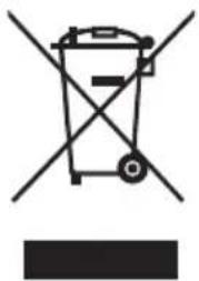
This symbol indicates that this product should not be disposed of with general household waste. This applies throughout the entire EU. In order to prevent any harm to the environment or health hazards caused by incorrect waste disposal, the product must be handed in for recycling so that the material can be disposed of in a responsible manner. When recycling your product, take it to your local collection facility or contact the place of purchase. They will ensure that the product is disposed of in an environmentally sound manner.
natural_image
Symbol of a trash bin crossed with no text or numbers, representing waste sorting or disposal (no text present)Specifications
Length 245 mm
Height 240 mm
Width 56 mm
Weight 1.3 kg
Magazine capacity 100 units
Pressure range 4–7 bar
Nail size 10–50 mm
natural_image
Line drawing of a hand holding a small mechanical component, with no visible text or symbolsnatural_image
Line drawing of a hand holding a mechanical component with a tool, no text or symbols presentnatural_image
Technical line drawing of a barcode scanner with mechanical components (no text or symbols)Användning
△ Viktigt:
natural_image
Technical line drawing showing two mechanical assembly steps with a central gear mechanism (no text or symbols)natural_image
Line drawing of a hand holding a tool with multiple metal components (no text or symbols)Felsökningsschema

Varning!
natural_image
Symbol of a trash bin crossed with no text or labels, accompanied by a black rectangular block below (no readable text or symbols)Specifikationer
Längd 245 mm
Höjd 240 mm
Bredd 56 mm
Vikt 1,3 kg
Magasinkapacitet 100 st
Tryckområde 4–7 bar
Spikstorlek 10–50 mm
Spikerpistol T-Dykkert
Art.nr. 40-7980 Modell XAGD50
natural_image
Line drawing of a hand holding a small mechanical component, with a close-up view of the handle and base (no text or symbols)natural_image
Line drawing of a hand holding a mechanical component with a tool, no text or symbols presentnatural_image
Technical line drawing of a mechanical device with a barcode bar inside (no text or symbols)Bruk
△Viktig:
natural_image
Technical line drawing showing two mechanical assembly steps with a central gear mechanism (no text or symbols)natural_image
Line drawing of a hand holding a tool with multiple metal components (no text or symbols)Feilsøking

Advarsel!
natural_image
Symbol of a trash bin with no text or labels, crossed by diagonal lines and a solid black rectangle below (no readable text or symbols)Spesifikasjoner
Lengde 245 mm
Høyde 240 mm
Bredde 56 mm
Vekt 1,3 kg
Magasinkapasitet 100 stk.
Trykkområde 4–7 bar
natural_image
Line drawing of a hand holding a small mechanical component, with a tool partially visible below (no text or symbols)natural_image
Line drawing of a hand holding a mechanical component with a tool, no text or symbols presentnatural_image
Technical line drawing of a mechanical device with a barcode bar inside (no text or symbols)Käyttö
△ Huom.!
natural_image
Technical line drawing showing two mechanical assembly steps with a central knob and rotating knob (no text or symbols)natural_image
Line drawing of a hand holding a tool with multiple metal components (no text or symbols)Vianhakutaulukko

Varoitus!
natural_image
Symbol of a trash bin crossed with no visible text or labelsTekniset tiedot
Pituus 245 mm
Korkeus 240 mm
Leveys 56 mm
Paino 1,3 kg
natural_image
Line drawing of a hand holding a small mechanical component, with no visible text or symbolsnatural_image
Line drawing of a hand holding a mechanical component with a tool, no text or symbols presentnatural_image
Technical line drawing of a mechanical assembly with a barcode bar inside (no text or symbols)Bedienung
△ Wichtig:
natural_image
Technical line drawing of a mechanical assembly with a central gear mechanism (no text or symbols)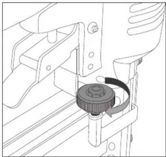
natural_image
Technical line drawing of a mechanical assembly with a gear and rotating component (no text or symbols)natural_image
Line drawing of a hand holding a tool with multiple metal components (no text or symbols)Fehlersuche

Warnung:
natural_image
Symbol of a trash bin crossed with no text or labels, accompanied by a black rectangular block below (no readable text or symbols)Technische Daten
Länge 24,5 cm
Höhe 24,0 cm
Breite 5,6 cm
Gewicht 1,3 kg
Declaration of Conformity
Declares that this product complies with the requirements of the following directives and standards
Machinery Directive 2006/42/EC
EN 792-13:2000+1
AFPS GS 2014:01
2006/42/EC ANNEX 1
EMC Directive Low
Voltage Directive
Henrik Alfredsson
Manager Technique & Quality
Insjön, Sweden, 2017-02-07
CLAS OHLSON AB, SE-793 85 INSJÖN, SWEDEN
Sverige
Postal 10 - 13 Market Place
Kingston upon Thames
Surrey
KT1 1JZ
Deutschland
Kundenservice Hotline: 040 2999 78111
E-Mail: kundenservice@clasohlson.de
Homepage
www.clasohlson.de

- ADJUSTABLE IMPACT DEPTH
- SPIKPISTOL T-DYCKERT SPIKERPISTOL NAULAIN T-DYCKERT STAUCHKOPFNAGLER
- Important:
- Viktig information:
- Safety
- Warning:
- Compressed air feed and connections
- Warning symbols on tool
- Product description
- Installation
- Suggestion for installation
- Lubrication
- Function and safety checks
- Loading
- Instructions for use
- △ Important:
- Setting the impact depth and impact force
- Adjusting the impact depth with the adjustment knob
- Adjusting the impact force with pressure regulator on air hose
- Removing a nail that has become jammed
- Troubleshooting
- Care and maintenance
- Responsible disposal
- Specifications
- Användning
- △ Viktigt:
- Felsökningsschema
- Varning!
- Specifikationer
- Spikerpistol T-Dykkert
- Bruk
- △Viktig:
- Feilsøking
- Advarsel!
- Spesifikasjoner
- Käyttö
- △ Huom.!
- Vianhakutaulukko
- Varoitus!
- Tekniset tiedot
- Bedienung
- △ Wichtig:
- Fehlersuche
- Warnung:
- Technische Daten
- Declaration of Conformity
- Sverige
- Deutschland
Brand : Cocraft
Model : HB18
Category : Compressor