HI 678-C - Compressor Cocraft - Free user manual and instructions
Find the device manual for free HI 678-C Cocraft in PDF.


| Product Type | Air Compressor |
| Brand | Cocraft |
| Model | HI 678-C |
| Power Source | Electric (230 V, 50 Hz) |
| Motor Power | 1.5 HP (1100 W) |
| Maximum Pressure | 8 bar (116 psi) |
| Tank Capacity | 6 L |
| Air Displacement | 120 L/min |
| Free Air Delivery | 90 L/min |
| Sound Level | 78 dB(A) |
| Dimensions (L x W x H) | 40 x 30 x 35 cm |
| Weight | 8.5 kg |
| Lubrication | Oil-free (maintenance-free) |
| Safety Features | Pressure relief valve, thermal overload protection |
| Pressure Regulator | Adjustable with gauge |
| Quick Connector | 1/4" BSP |
| Included Accessories | Air hose (5 m), tire inflator, blow gun |
| Operating Temperature | 5 °C to 40 °C |
| Protection Class | IP20 |
Frequently Asked Questions - HI 678-C Cocraft
User questions about HI 678-C Cocraft
0 question about this device. Answer the ones you know or ask your own.
Ask a new question about this device
Download the instructions for your Compressor in PDF format for free! Find your manual HI 678-C - Cocraft and take your electronic device back in hand. On this page are published all the documents necessary for the use of your device. HI 678-C by Cocraft.
USER MANUAL HI 678-C Cocraft
natural_image
Cocraft industrial device with black handle and blue base, no visible text or symbols on bodyArt.no Model
41-1423
11DIW1202

Important!
Read the entire instruction manual carefully and make sure that you fully understand it before you use the equipment. Keep the manual for future reference.
Viktig information:
Original instructions
Bruksanvisning i original
Originalbruksanvisning
Please read the entire instruction manual before using the product and then save it for future reference. We reserve the right for any errors in text or images and any necessary changes made to technical data. In the event of technical problems or other queries, please contact our Customer Services (see address details on the back).
Safety
Warning: Read the entire instruction manual before using the product and keep it for future reference. Make sure that you have read and understood the instruction manual before using the tool. Failure to follow the safety instructions could lead to serious personal injuries.
Warning: Do not exceed the recommended working pressure, 6.3 bar (90 psi).
Too high a pressure can cause the impact wrench to explode which may result in serious or fatal personal injuries.
a) Disconnect the impact wrench from the air hose before changing sockets/tools, before servicing it, and as soon as you have finished using it.
b) Always wear safety glasses and ear defenders when the impact wrench is in use.
c) Do not pull the trigger whilst the air hose is being connected.
d) Only use tools and accessories designed for use with pneumatic/air powered tools. Warning: Only use impact sockets which are designed for use with impact wrenches. Normal sockets designed for use with hand tools, worn sockets or damaged sockets should never be used with an impact wrench.
e) Do not pull the trigger before the socket has securely mated with the nut or bolt. The socket must grip the head of the bolt or nut securely.
f) Before using the tool, make sure that all connections are tight and that the air hose is not damaged in any way.
g) WARNING: Always disconnect the air hose from the impact wrench before attaching the socket/accessory and before carrying out any maintenance.
h) Neither this tool nor its accessories must be modified in any way.
Workplace hazards
a) Keep your work area clean and well-illuminated.
b) The most common causes of serious or fatal injury in the workplace are related to slipping, tripping or falling. Watch out for hanging cables or hoses and slippery floors.
c) Keep a firm footing and good balance at all times.
d) Repetitive work movements, uncomfortable work postures and vibrating tools can be harmful to hands and arms.
e) Exposure to high noise levels can cause permanent hearing loss. Always use ear protection.
f) Avoid inhaling dust particles or contaminants which might be harmful to your health.
g) Keep pets and bystanders out of the work area when the tool is being used.
h) This tool is not designed for use in explosive atmospheres and is not insulated for contact with electric power sources.
Personal safety precautions
a) Pay attention to what you are doing and use common sense when using pneumatic tools. Never use any hand tool, pneumatic or power tool if you are tired or under the influence of drugs, alcohol or medication. One moment of inattention while using a power tool may result in serious injury.
b) Wear protective clothing. Always wear safety glasses. Using protective clothing such as dust masks, non-slip safety shoes, helmets and ear defenders when needed decreases the risk of injury.
c) Avoid accidental starts. Never hold your finger on the trigger when connecting the air hose or changing a socket.
d) Do not overreach. Make sure you stand steady and well balanced at all times. This will allow you to have more control in unexpected situations.
e) Do not wear loose-fitting clothing or jewellery. Keep hair, clothes and loose-fitting gloves away from moving parts. Loose-fitting clothes, jewellery or long hair could become caught in moving parts and result in serious injury.
f) Dust extraction or collection equipment should be used whenever the work environment contains large amounts of dust.
g) Hold the product by its insulated gripping surfaces whenever using the tool where it could come in contact with hidden live wiring. Contact with live wires will make the metal parts of the tool live and could shock the user.
h) Avoid direct contact with accessories during use.
Projectile hazards
a) Parts of the workpiece, accessories or even the socket can fly off at high speed.
b) Always wear impact-rated safety eyewear when using the impact wrench. Select suitable safety eyewear that provides adequate protection for the task you are performing.
c) Ensure that the workpiece is securely fastened or clamped.
Entanglement hazards
a) Loose-fitting clothing, jewellery, necklaces or hair which becomes entangled with the tool could result in strangulation, constriction or crushing.
b) Gloves can become entangled in the rotating drive, resulting in severed or broken fingers.
c) Rubber-coated or steel-reinforced gloves can easily become caught in rotating sockets or extension bars.
d) Do not wear loose-fitting gloves or gloves with cut or frayed fingers.
e) Never hold onto the drive anvil, socket or extension bar.
f) Keep hands away from rotating drive anvils.
Explanation of symbols

Read the instruction manual before operating the tool.

Always wear ear protection.

Always wear eye protection.
Product description
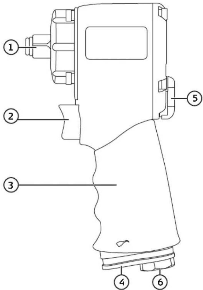
- 12 " square drive anvil
- Trigger
- Handle
- Exhaust port
- Function selector
- Air inlet coupling
Installation
Air hose connector
natural_image
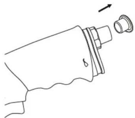
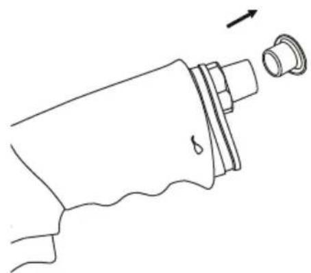
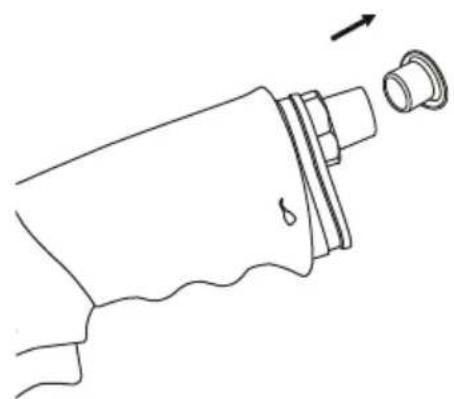
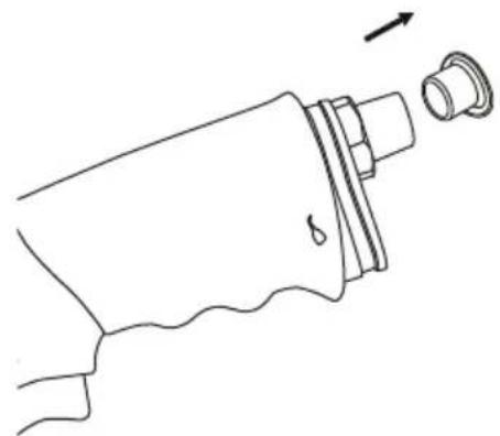
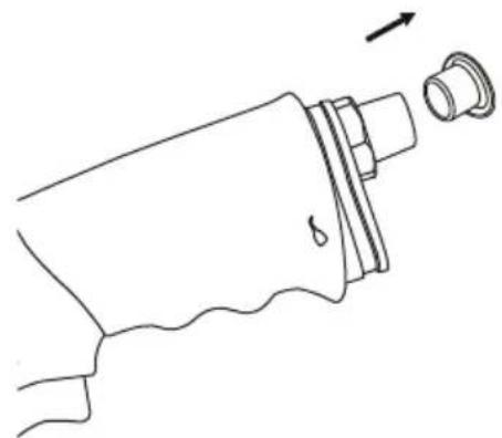
Line drawing of a hand holding a small object with a wavy line, showing a mechanical part and an arrow indicating direction (no text or symbols)- If a plug has been fitted to the air coupling (6) to protect it during shipment from the factory it must now be removed.
natural_image
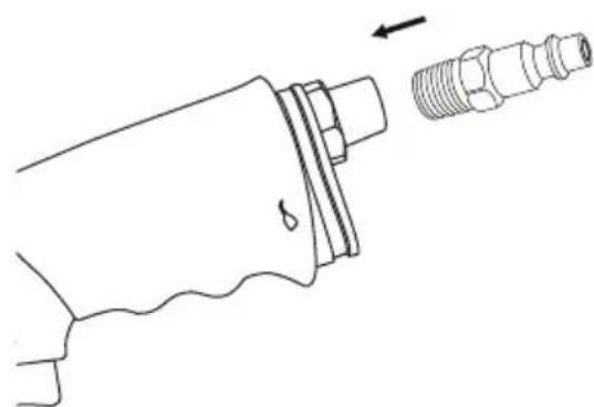
Technical line drawing of a mechanical component with threaded end and wavy base (no text or symbols)- Screw the included air inlet nipple into the air inlet coupling. Use some form of thread sealant to ensure that the seal is airtight.
natural_image
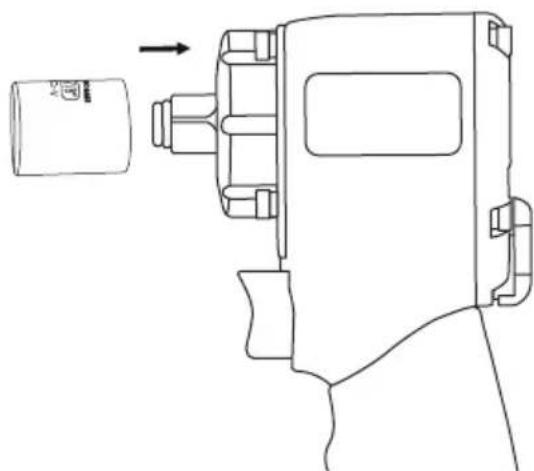
Line drawing of a mechanical device with a cylindrical component and an arrow indicating direction (no text or symbols)- Fit a socket onto the anvil (1). Use only undamaged impact sockets.
natural_image
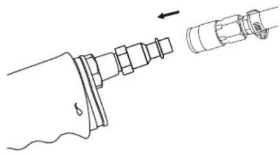
Technical line drawing of a mechanical assembly with no visible text or symbols- Connect the quick-connect coupling of the air hose to the air inlet nipple on the impact wrench.
Connection to the air supply system
a) This tool must only be connected to a clean, filtered and dry air supply which provides an air pressure at the tool of 6.3 bar (90 psi). Warning: Too high a pressure will reduce the lifespan of the tool and could cause serious personal injuries.
b) Connect the tool to the air supply using a hose designed for high pressure air.
c) Fit a quick-connect coupling in the air hose and a regular inlet nipple onto the impact wrench. Do not attach a quick-connect coupling to the impact wrench itself, as this would retain pressure in the tool even when the air hose has been disconnected.
d) In order for the tool to work at its full capacity, the air compressor must provide the tool with at least the tool's rated air consumption.
e) Only use air hoses of the recommended dimension and length. Do not connect the tool to the air compressor without incorporating an easy to reach and operate air cut-off valve.
f) Make sure that any water which has condensed in the tank of the air compressor or the air hoses is emptied out regularly to prevent water being delivered into the tool. Water in the system could freeze in the hose or cause the tool to rust.
Motor and impact mechanism lubrication
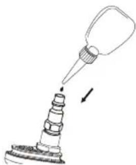
The motor and the impact mechanism are lubricated with grease from the factory but might need to be lubricated further if the impact is used daily. Add 4–5 drops of oil designed for air tools and machines into the air coupling nipple on the impact wrench before connecting the air hose. Repeat after every 3–4 hours of use.
Run the impact wrench for a few seconds under no load with a rag over the exhaust port to catch any excess oil.
natural_image
Diagram of a bottle being inserted into a cylindrical container with a pointed tip (no text or symbols)Instructions for use Undoing nuts/bolts
- Fit a hexagon impact socket which fits exactly onto the head of the screw/bolt or nut which you want to undo onto the anvil of the impact wrench (1).
- Fit the socket fully over the nut/bolt you wish to loosen.
- Grip the impact wrench firmly by the handle (3).
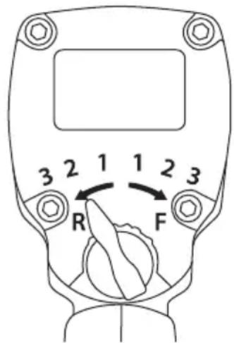
- Turn the selector (5) left to the reverse position (R) and choose an impact force 1, 2 or 3 (low-medium-high). Always begin with the lowest force (1) and then increase if necessary.
- Pull the trigger (2).
Note: Do not run the impact wrench for more than 15 sec at a time in the same direction if the nut/bolt does not loosen. If the nut/bolt does not come undone:
- Change the direction of rotation using the selector (3) and drive the impact wrench in the opposite direction for a couple of seconds.
- Switch the direction of rotation back again and run the wrench in the original direction.
Tightening nuts/bolts
Note:
- When doing up nuts/bolts using an impact wrench, a torque bar (sold separately) with the correct torque setting should be inserted between the impact wrench and the impact socket, otherwise the nut/bolt might be overtightened and damage the fastener and/or the material it is fastening.
-
When fitting wheels onto vehicles a final check of the wheel nut/bolt torque should always be made using a torque wrench.
-
Screw the wheel nuts/bolts in place by hand at least 3 complete turns in order to prevent damaging the threads when they are tightened using the impact wrench.
- Fit a hexagon impact socket which fits exactly onto the head of the screw/bolt or nut which you want to undo onto the anvil of the impact wrench (1).
- Fit the socket fully over the nut/bolt you wish to loosen.
- Grip the impact wrench firmly by the handle (2).
- Turn the selector (3) right to the forward position (F) and choose an impact force 1, 2 or 3 (low-medium-high). Always begin with the lowest force (1) and then increase if necessary.
- Squeeze the trigger and release it when the nut/bolt has been tightened.
Note: After fastening, a final check of the torque should always be made using a torque wrench.
Troubleshooting
| The impact wrench fails to deliver full power or does not rotate at all. | The tool is unlubricated. Lubricate the tool with appropriate oil, refer to the Lubrication section. |
| Low air pressure. Adjust the pressure regulator on the compressor to 90 psi/6.3 bar. | |
| The function selector is in the wrong position. Check and adjust. | |
| The pressure keeps falling. Air hose is too long or has too small a bore causing pressure drop. Check and replace it with a shorter hose or one with a larger bore. | |
| Worn/broken rotor blades in air motor. Replace. | |
| Water or spray blows out of the exhaust. Empty any condensation from the tank and hose. | |
| If the impact wrench has been left unused for a long time the rotor blades in the air motor might have stuck. Lubricate the tool with appropriate oil, refer to the Lubrication section. Then run the tool on High impact force for about 30 seconds. Refer to Operating instructions. If this doesn't help, repeat the procedure. |
Responsible disposal
The product should be disposed of in accordance with local regulations. If you are unsure how to proceed, contact your local council.
Specifications
Socket drive 12 " square
Max. torque 678 Nm
Max speed 10 000 rpm
Max working pressure 6.3 bar
Air consumption 200 L/min
Vibration 2.8 m/s²
Noise level 94 dBA
Air coupling 1/4"
Air hose bore < ∅ 9.5 mm
Length 9.9 cm
Weight 1.4 kg
Mutterdragare 12 "
Art.nr 41-1423 Modell 11DIW1202
Installation
Luftnippel
natural_image
Line drawing of a hand holding a small object with a wavy line, showing an arrow indicating direction (no text or symbols)natural_image
Technical line drawing of a mechanical component with threaded fitting and wavy base (no text or symbols)natural_image
Line drawing of a mechanical device with a cylindrical component and an arrow indicating direction (no text or symbols)natural_image
Technical line drawing of a mechanical assembly with no visible text or symbolsnatural_image
Diagram of a mechanical tool with a pointed tip and threaded base, showing a downward arrow (no text or symbols)Användning
Lossa muttrar/skruvar
Installasjon
Luftenippel
natural_image
Line drawing of a hand holding a small object with a wavy line, showing a droplet and a cap (no text or symbols)natural_image
Technical line drawing of a mechanical component with threaded end and wavy base (no text or symbols)natural_image
Line drawing of a mechanical device with a cylindrical component and an arrow indicating direction (no text or symbols)natural_image
Technical line drawing of a mechanical assembly with no visible text or symbols- Luftslangens hurtigkobling kobles til nippelen på muttertrekkeren.
natural_image
Simple line drawing of a funnel pouring liquid into a stepped container (no text or symbols)Bruk
Asentaminen
Ilmanippa
natural_image
Line drawing of a hand holding a small object with a wavy line, showing a mechanical part and a separate cylindrical component (no text or symbols)natural_image
Technical line drawing of a mechanical component with threaded end and wavy base (no text or symbols)natural_image
Line drawing of a mechanical device with a cylindrical component and an arrow indicating direction (no text or symbols)natural_image
Technical line drawing of a mechanical assembly with no visible text or symbolsnatural_image
Diagram of a mechanical tool with a pointed tip and stepped base, showing a downward arrow (no text or symbols)Käyttö
Installation Luftnippel
natural_image
Line drawing of a hand holding a small object with a wavy line, showing a mechanical part and an arrow indicating direction (no text or symbols)natural_image
Technical line drawing of a mechanical component with threaded end and wavy base (no text or symbols)natural_image
Line drawing of a mechanical device with a cylindrical component and an arrow indicating motion (no text or symbols)natural_image
Technical line drawing of a mechanical assembly with a tool and pipe connection (no text or symbols)natural_image
Diagram of a pipette dispensing liquid into a multi-tiered container (no text or symbols)Declaration of Conformity
Declares that this product complies with the requirements of the following directives and standards
11DIW1202 (Vendor model no.)
YF-207J4 (Factory model no.)
Machinery Directive
2006/42/EC
EN ISO 11148-6
Henrik Alfredsson
Manager Technique & Quality
Insjön, Sweden, 2017-07-13
Sverige
Postal 10 - 13 Market Place
Kingston Upon Thames
Surrey
KT1 1JZ
Deutschland
Kundenservice Hotline: 040 2999 78111
E-Mail: kundenservice@clasohlson.de
Homepage
www.clasohlson.de


- Important!
- Viktig information:
- Safety
- Workplace hazards
- Personal safety precautions
- Projectile hazards
- Entanglement hazards
- Explanation of symbols
- Product description
- Connection to the air supply system
- Motor and impact mechanism lubrication
- Instructions for use Undoing nuts/bolts
- Tightening nuts/bolts
- Note:
- Troubleshooting
- Responsible disposal
- Specifications
- Mutterdragare 12 "
- Installation
- Luftnippel
- Användning
- Lossa muttrar/skruvar
- Installasjon
- Luftenippel
- Bruk
- Käyttö
- Installation Luftnippel
- Declaration of Conformity
- Sverige
- Deutschland
Brand : Cocraft
Model : HI 678-C
Category : Compressor