
PRO A850-M - Mill Cocraft - Free user manual and instructions
Find the device manual for free PRO A850-M Cocraft in PDF.


| Product Type | Angle Grinder (referred to as Mill) |
| Brand | Cocraft |
| Model | PRO A850-M |
| Voltage | 230–240 V, 50 Hz |
| Rated Power | 850 W |
| No-Load Speed | 12,000 rpm |
| Disc Diameter | 125 mm |
| Disc Bore | 22.2 mm |
| Spindle Thread | M14 |
| Weight (without accessory) | 1.6 kg |
| Sound Pressure Level (LpA) | 96 dB(A), K=3 dB |
| Sound Power Level (LwA) | 107 dB(A), K=3 dB |
| Vibration Level (main grip) | 5.88 m/s², K=1.5 m/s² |
| Vibration Level (side handle) | 4.03 m/s², K=1.5 m/s² |
| Safety Features | Spindle lock, safety guard, auxiliary handle, restart prevention |
| Included Accessories | Pin spanner, grinding disc guard, cutting disc guard, auxiliary handle |
| Applicable Disc Types | Grinding discs, cutting discs, wire brushes, sanding pads (with appropriate guard) |
| Maintenance | Keep ventilation slots clean; use mild cleaner; replace damaged cord by qualified personnel |
| Standards Compliance | EN 60745-1, EN 60745-2-3, EMC Directive 2014/30/EU |
Frequently Asked Questions - PRO A850-M Cocraft
User questions about PRO A850-M Cocraft
0 question about this device. Answer the ones you know or ask your own.
Ask a new question about this device
Download the instructions for your Mill in PDF format for free! Find your manual PRO A850-M - Cocraft and take your electronic device back in hand. On this page are published all the documents necessary for the use of your device. PRO A850-M by Cocraft.
USER MANUAL PRO A850-M Cocraft
Read the entire instruction manual carefully and make sure that you fully understand it before you use the equipment. Keep the manual for future reference.
Viktig information:
natural_image
Exterior view of a black and silver Codaft series electric grinder on a textured dark surface (no text or symbols visible)Art.no Model
40-9927
PGA125HB.2
Ver. 20170131
Original instructions
Bruksanvisning i original
Originalbruksanvisning
Please read the entire instruction manual before using the product and then save it for future reference. We reserve the right for any errors in text or images and any necessary changes made to technical data. In the event of technical problems or other queries, please contact our Customer Services (see address details on the back).
Safety
General Power Tool Safety Warnings – Personal Safety
WARNING! Read all safety warnings and all instructions. Failure to follow the warnings and instructions may result in electric shock, fire and/or serious injury.
SAVE ALL WARNINGS AND INSTRUCTIONS FOR FUTURE REFERENCE.
The term “power tool” in the warnings refers to your mains-operated (corded) power tool or battery-operated (cordless) power tool.
1) Work area safety
a) Keep work area clean and well lit. Cluttered or dark areas invite accidents.
b) Do not operate power tools in explosive atmospheres, such as in the presence of flammable liquids, gases or dust. Power tools create sparks which may ignite the dust or fumes.
c) Keep children and bystanders away while operating a power tool. Distractions can cause you to lose control.
2) Electrical safety
a) Power tool plugs must match the outlet. Never modify the plug in any way. Do not use any adapter plugs with earthed (grounded) power tools. Unmodified plugs and matching outlets will reduce risk of electric shock.
b) Avoid body contact with earthed or grounded surfaces, such as pipes, radiators, ranges and refrigerators. There is an increased risk of electric shock if your body is earthed or grounded.
c) Do not expose power tools to rain or wet conditions. Water entering a power tool will increase the risk of electric shock.
d) Do not abuse the cord. Never use the cord for carrying, pulling or unplugging the power tool. Keep cord away from heat, oil, sharp edges or moving parts. Damaged or entangled cords increase the risk of electric shock.
e) When operating a power tool outdoors, use an extension cord suitable for outdoor use. Use of a cord suitable for outdoor use reduces the risk of electric shock.
f) If operating a power tool in a damp location is unavoidable, use a residual current device (RCD) protected supply. Use of an RCD reduces the risk of electric shock.
3) Personal safety
a) Stay alert, watch what you are doing and use common sense when operating a power tool. Do not use a power tool while you are tired or under the influence of drugs, alcohol or medication. A moment of inattention while operating power tools may result in serious personal injury.
b) Use personal protective equipment. Always wear eye protection. Protective equipment such as dust mask, non-skid safety shoes, hard hat, or hearing protection used for appropriate conditions will reduce personal injuries.
c) Prevent unintentional starting. Ensure the switch is in the off-position before connecting to power source and/or battery pack, picking up or carrying the tool. Carrying power tools with your finger on the switch or energising power tools that have the switch on invites accidents.
d) Remove any adjusting key or wrench before turning the power tool on. A wrench or a key left attached to a rotating part of the power tool may result in personal injury.
e) Do not overreach. Keep proper footing and balance at all times. This enables better control of the power tool in unexpected situations.
f) Dress properly. Do not wear loose clothing or jewellery. Keep your hair, clothing and gloves away from moving parts. Loose clothes, jewellery or long hair can be caught in moving parts.
g) If devices are provided for the connection of dust extraction and collection facilities, ensure these are connected and properly used. Use of dust collection can reduce dust related hazards.
4) Power tool use and care
a) Do not force the power tool. Use the correct power tool for your application. The correct power tool will do the job better and safer at the rate for which it was designed.
b) Do not use the power tool if the switch does not turn it on and off. Any power tool that cannot be controlled with the switch is dangerous and must be repaired.
c) Disconnect the plug from the power source and/or the battery pack from the power tool before making any adjustments, changing accessories, or storing power tools. Such preventive safety measures reduce the risk of starting the power tool accidentally.
d) Store idle power tools out of the reach of children and do not allow persons unfamiliar with the power tool or these instructions to operate the power tool. Power tools are dangerous in the hands of untrained users.
e) Maintain power tools. Check for misalignment or binding of moving parts, breakage of parts and any other condition that may affect the power tool's operation. If damaged, have the power tool repaired before use. Many accidents are caused by poorly maintained power tools.
f) Keep cutting tools sharp and clean. Properly maintained cutting tools with sharp cutting edges are less likely to bind and are easier to control.
g) Use the power tool, accessories and tool bits, etc. in accordance with these instructions, taking into account the working conditions and the work to be performed. Use of the power tool for operations different from those intended could result in a hazardous situation.
5) Service
a) Have your power tool serviced by a qualified repair person using only identical replacement parts. This will ensure that the safety of the power tool is maintained.
Special safety warnings applicable to grinding, dressing, brushing, or cutting
- This power tool is intended for grinding, dressing, brushing and cutting. Read all safety warnings, instructions, illustrations, and specifications that are included with this tool. Neglecting to follow all of the instructions listed below can result in electric shock, fire and/or serious injury.
- Polishing is not recommended with this power tool. The use of this power tool to perform tasks for which the tool was not intended, can lead to danger and personal injury.
- Do not use accessories which are not intended to be used with this tool and which are not recommended by the manufacturer. Even if the accessory can be attached to your power tool, there is no guarantee that it can be used safely.
- The accessory's rated speed must at least correspond to the power tool's maximum rated speed. Accessories which rotate faster than their rated speed can break and shatter.
- The accessory's outer diameter and size must fall within the rated capacity of your power tool. If an accessory is the wrong size, it will not fit the guard and will not be able to be controlled properly.
- The spindle size of the wheels, flanges, and backing plates or other accessories must fit the spindle on your power tool correctly. Ill-fitting/incorrectly sized accessories will end up out of balance, vibrate violently, and may lead to loss of control.
- Do not use damaged accessories. Inspect the accessory and make sure there are no splits or cracks in the grinding wheels; cracks or wear and tear on the backing plates, or loose or torn bristles on the steel brush wheels.
If you drop your power tool or accessory, check for damage. If the accessory is damaged, use a new/undamaged accessory. After inspecting the tool and attaching an accessory, keep yourself and others outside of the power tool's danger zone and let it run at full speed for one minute. Damaged accessories will normally break during this test period.
- Wear personal protective equipment. Depending on how you use the machine; use a visor/face protection or safety glasses. If necessary use a mask, ear protection, gloves, and apron/work clothing to protect you from small shards of metal or splinters from the work object. The eye protection you use must be able to protect against flying debris produced in different working positions. The breathing protection should be able to filter any particles produced by the work. Prolonged exposure to high levels of noise can result in hearing damage.
- Keep bystanders at a safe distance from the work area. Everyone who visits the place of work must wear personal protective equipment. Debris from the workpiece or from a damaged accessory can fly off and injure people outside of the immediate work area.
- Only hold the power tool by its isolated grip when working in positions where the cut-off wheel might possibly cut through hidden cables or its own mains lead. Cut-off wheels which come in contact with an electric cable can electrify metal parts of the power tool and subject the user to an electric shock.
- Position the mains lead well away from the rotating accessory. If you lose control, the lead can be sliced through or become entangled and pull your hand or arm into the rotating accessory.
- Never put the power tool down before the accessory has completely stopped rotating. The rotating accessory can become stuck in the material resulting in loss of control.
- Do not run the power tool when you are carrying it. Unintentional contact with the rotating accessory can cause clothing to become caught and pull the tool towards your body.
- Regularly clean the motor's ventilation ports. The motor's fan pulls in dust, which gets inside the outer casing and a build up of this collected metal dust can lead to electrical dangers.
- Do not use the power tool near flammable materials. Sparks can easily ignite flammable material.
- Do not use accessories which require liquid coolants. The use of water or other liquid coolants can result in electric shock or electrocution.
Kickback
A kickback is a sudden counteraction to a jammed or stuck disc, backing plate, brush, or some other accessory. A jammed or stuck rotating accessory results in the power tool thrusting violently in the opposite direction.
For example, if a grinding wheel gets stuck or is jammed into the object, the edge of the grinding wheel can either grab onto the object and dig itself down deeper or be thrust upward. The grinding wheel is either thrown towards or away from the user depending on the rotation of the grinding wheel.
The grinding wheel can also break under these circumstances. Kickbacks are the result of the power tool being used in an incorrect manner, on incorrect objects, or under incorrect conditions and can be avoided by observing the following precautions.
- Hold the power tool steady and position your arms and body so that you can adequately handle any kickback. Always use the side-handle if there is one for maximum control during kickback and to be able to control the torque produced by turning the angle grinder on. Kickbacks or reactions to torque can be controlled by the user if the required safety precautions are followed.
- Never place your hand near the rotating accessory. The accessory can be thrown back onto your hand.
- Do not stand in the area in which the power tool could possibly end up if it were to kick back. A kickback forces the tool in the opposite direction of the grinding wheel's rotation.
- Be extra careful when working on corners, sharp edges, etc. Avoid bouncing along and getting the accessory stuck. Corners, sharp edges, and bouncing have a tendency to get the rotating accessory stuck and lead to loss of control of the tool.
- Never fit a circular saw wood cutting blade or other toothed saw blade. Such blades frequent lead to kickbacks and loss of control.
Specific safety precautions for grinding and cutting with a cut-off wheel
- Only use those types of disc/wheel which are recommended for the power tool and a special shatter guard plate designed for the selected cut-off wheel. Disc/wheels which are not designed for use with the power tool cannot be properly protected against and can be dangerous.
- The shatter guard must be fitted to the power tool correctly and adjusted to provide maximum safety so that the user is exposed to as little of the disc/wheel as possible. The shatter guard helps to protect the user from shards of shattered disc/wheel and unintentional contact with the disc/wheel.
- The wheels/discs must only be used for the recommended work task. For example: Do not grind with the edge of a cut-off wheel. Cut-off wheels are intended for cutting using the edge. If force is exerted on the face, they can break.
- Always use undamaged flanges of a correct size and shape for the wheel you have selected. Correct flanges support the wheel and minimize the risk of it breaking. Flanges for cut-off wheels can be different from those which are used for grinding discs.
- Never use worn-down wheels designed for use with a larger power tool. Wheels intended for larger power tools do not have the same speed rating as those intended for use with smaller tools and can shatter.
Additional safety precautions for cutting with a cut-off wheel
- Do not force the cut-off wheel or apply too much pressure. Do not try to cut too deeply. Overloading the wheel increases the pressure and the likelihood of the wheel twisting or getting stuck in the cut and increases the chances of kickback or the wheel breaking.
- Never stand in line with or behind the rotating wheel. When the wheel rotates away from you during use, a kickback can force the rotating wheel and the power tool in the opposite direction, i.e. towards you.
- When the wheel gets stuck or if you for some reason want to stop cutting, turn off the power tool and hold it still until the wheel has stopped completely. Never try to remove the cut-off wheel from the cut while the wheel is moving because it can result in a kickback. Examine and take the necessary measures to minimize the risk of the wheel jamming.
- After stopping, do not resume cutting with the wheel in the workpiece. Let the wheel reach full speed first and then continue carefully in the previous cut. The wheel can get stuck, wander out of the cut or kickback if cutting is restarted with the wheel in the workpiece.
- Support large planks or other large workpieces in order to minimize the risk of getting stuck or kickback. Large boards tend to bow under their own weight. Boards should be support from underneath, both near the cutting line and near the edges of the board on both sides of the cut-off wheel.
- Be especially careful when plunge sawing into walls or objects where it is not possible to see what one is sawing. The blade can cut into gas or water pipes, electric cables, or other objects which can cause kickback.
Specific safety warnings for sanding
a) Do not use sanding discs which are too large for your power tool.
Follow manufacturers' recommendations when selecting sanding discs.
Large sanding paper extending beyond the backing pad presents a laceration hazard and may cause snagging, tearing of the disc or kickback.
Specific safety warnings for wire brushing
a) Be aware that bristles can dislodge from the wire brush even during normal use. Do not overstress the wire brush by applying excessive pressure.
Loose wire bristles can easily penetrate light clothing and/or skin.
b) If the use of a guard is recommended for wire brushing, do not allow any interference of the wire wheel or brush with the guard. The wire wheel or brush may expand in diameter due to work load and centrifugal forces.
Vibration
- The measurement of the vibration emission level declared in this instruction manual has been carried out in accordance with a standardised test method described in EN 60745 and can be used for comparing one power tool with another.
- The measurement method may also be used for a preliminary assessment of vibration exposure.
- The declared vibration emission level applies when the power tool is used in accordance with this instruction manual. If however, the power tool is used for other purposes and with other accessories or has not been properly maintained, the vibration emission level could increase significantly over the total working period.
- For an exact assessment of the vibration exposure, the times when the tool is switched off or running idle should also be taken into account. This significantly reduces the vibration exposure over the total working period. Decide upon safety measures to protect the operator from the effects of vibration during all types of use.
Product safety symbols

Read the entire instruction manual.

Always use safety glasses, ear defenders and a face mask.
Product description
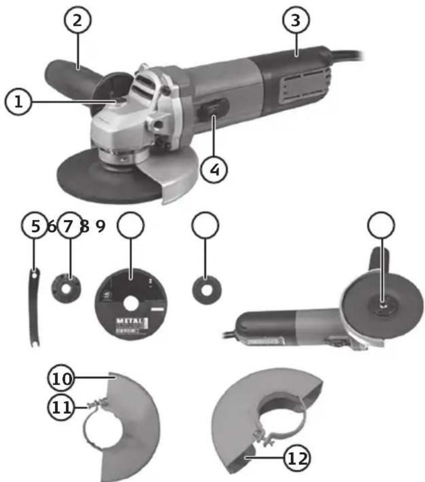
- Spindle lock
- Auxiliary handle
- Rear hand grip with motor ventilation slits
- [I/0] On/off power switch
- Pin spanner
- Outer flange nut
- Cut-off disc (sold separately)
- Inner flange washer
- Spindle
- Sanding/Grinding disc shatter guard
- Locking screw
- Cut-off disc shatter guard
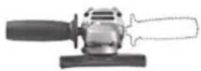
Auxiliary handle
Always use the auxiliary handle when working with the angle grinder. Attach the handle to either the left or right of the tool depending on the application.
Operating instructions
Important:
- Always remove the plug from the socket before carrying out adjustment, servicing or maintenance.
- Use only ∅ 125 mm discs or wheels with a bore of 22 mm.
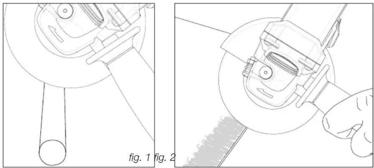
- Cut-off discs must only be used for cutting (fig. 1), they must never be subjected to side forces.
- When grinding (fig. 2), only use grinding discs (depressed centre grinding wheels) which are designed for surface grinding, as these discs are designed to withstand side pressures caused by bending.
- Replace the grinding disc when it is worn down to ∅ 85 mm.
natural_image
Technical line drawing showing two views of a mechanical device with a tool, labeled 'fig. 1' and 'fig. 2' (no text or symbols on the diagram itself)Fitting and removing discs
Warning: Always remove the plug from the socket before fitting and removing discs.
natural_image
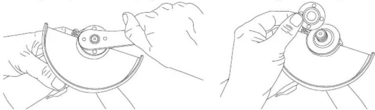
Line drawings of hands using a mechanical tool to adjust a component (no text or symbols present)Press and hold in the spindle lock button (1).
Remove the outer flange nut (6) using the spanner (5).
Place a disc onto the inner flange washer.
Refit the outer flange nut, hold in the spindle lock button and tighten the nut using the pin spanner. Release the spindle lock button and check that the disc rotates freely, is centred and securely fastened.
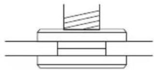
Note: The outer flange nut is designed to hold discs of various thicknesses. When using discs that are more than 1/8" (3.17 mm) thick,
natural_image
Pure mechanical assembly diagram showing layered components with no text or symbols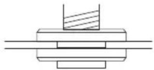
natural_image
Pure mechanical assembly diagram showing a cylindrical component with a hatched section, no text or symbols presentplace the outer flange nut on the spindle so that the raised centre fits into the centre of the wheel. If the disc you are fitting is 1/8" thick or less, place the flange nut on the spindle so that the raised centre is not against the wheel.
Shatter guard
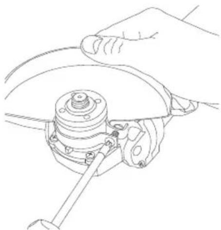
The angle grinder comes with 2 shatter guards, one for cutting discs (12) and one for grinding discs (10). Fit the correct guard onto the angle grinder depending on the type of disc used. Adjust the position of the shatter guard by loosening and tightening the locking screw (11). The nut on the locking screw is there to prevent the screw from being screwed all the way out. It is sufficient to tighten and loosen the screw only; you don't need to tighten the nut. Note: One of the shatter guards must always be fitted when the angle grinder is used.
natural_image
Line drawing of hands operating a mechanical component with a wrench (no text or symbols)Switching on/off
natural_image
Line drawing of a hand pressing a button on a mechanical component (no text or symbols)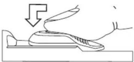
natural_image
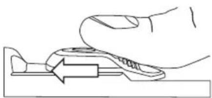
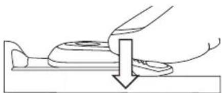
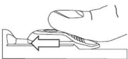
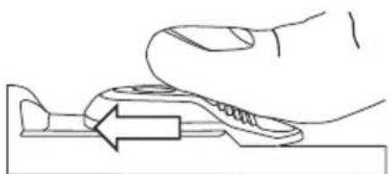
Line drawing of a hand pressing down on a shoe (no text or symbols)Switching on: Slide the power switch (4) forwards using your thumb to switch the angle grinder on. To lock the switch in the ON position, press the front of the switch down.
natural_image
Diagram of a mechanical assembly with a downward arrow indicating force or direction (no text or symbols)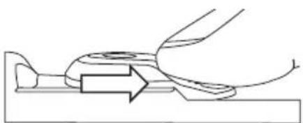
natural_image
Diagram of a mechanical component with an arrow indicating direction (no text or symbols)Switching off: Press down on the rear of the switch to switch the angle grinder off. The power switch is spring-loaded and switches the angle grinder off by automatically returning to the OFF position.
Note: Always keep your thumb close to the power switch so you can switch the power tool off quickly if necessary.
Note: If the power supply to the angle grinder is interrupted (e.g. by a power cut) when the power switch is set to ON, the angle grinder will not restart automatically when the power is restored. You will need to press down the rear of the power switch and let the spring return it to its original position before the angle grinder can be started again. This is a safety feature to prevent the angle grinder from starting unintentionally.
Care and maintenance
- Always unplug the mains lead from the wall socket before cleaning or maintenance of any sort.
- Keep the motor ventilation openings (3) free from contaminants.
- Clean the angle grinder using a lightly moistened cloth. Use only mild cleaning agents, never solvents or corrosive chemicals.
- If the mains lead is damaged it should only be replaced by a qualified electrician.
- If the angle grinder is not to be used for an extended period, it should be unplugged and stored in a dry and dust-free location out of reach of children.
Troubleshooting guide
| The angle grinder will not switch on. | Make sure that the mains lead is undamaged and securely plugged into a wall socket.Make sure that the wall socket is live. |
| The angle grinder runs slowly. | Remember not to press against the workpiece too hard. |
| Heavy vibrations. | Wheel/disc damaged or out of balance. Check the alignment and refit accessory. Replace the damaged accessory. |
Responsible disposal
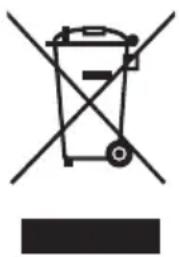
This symbol indicates that this product should not be disposed of with general household waste. This applies throughout the entire EU. In order to prevent any harm to the environment or health hazards caused by incorrect waste disposal, the product must be handed in for recycling so that the material can be disposed of in a responsible manner. When recycling your product, take it to your local collection facility or contact the place of purchase. They will ensure that the product is disposed of in an environmentally sound manner.
natural_image
Symbol of a trash bin with crossed lines indicating no waste, and a solid black rectangle below (no text or labels)Specifications
Supply voltage 230–240 V, 50 Hz
Rated power 850 W
No-load speed 12000 rpm
Disc diameter 125 mm
Bore 22.2 mm
Spindle thread M14
Sound pressure LpA 96 dB(A), K: 3 dB
LwA 107 dB(A), K: 3 dB
Vibration level
at main hand grip a_h,AG 5.88 m/s ^2 , K: 1.5 m/s ^2
side handle a_h,AG 4.03 m/s ^2 , K: 1.5 m/s ^2
Weight 1.6 kg (without abrasive accessory)
Vinkelslip
Art.nr 40-9927 Modell PGA125HB.2
natural_image
Technical illustration showing two views of a mechanical tool with a hand operating the workpiece (no text or symbols present)natural_image
Line drawings of hands using a tool to adjust or install a mechanical component (no text or symbols present)natural_image
Line drawing of a hand using a tool to adjust or install a mechanical component (no text or symbols present)På/av
natural_image
Line drawing of a hand pressing a tool on a cutting board (no text or symbols)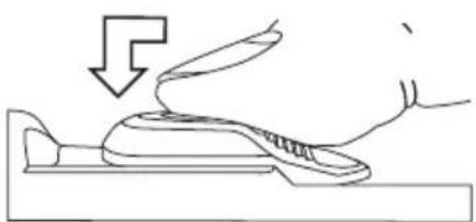
natural_image
Line drawing of a hand pressing down on a piece of shoe (no text or symbols)natural_image
Diagram of a hand pressing down on a mechanical component (no text or symbols)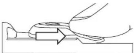
natural_image
Pure mechanical diagram showing a lever mechanism with no text or symbolsnatural_image
Symbol of a trash bin crossed with no text or labels, accompanied by a blank rectangular block below (no text or symbols present)Specifikationer
Nätanslutning 230–240 V, 50 Hz
Märkeffekt 850 W
Varvtal, obelastad 12000 v/min
Skivdiameter 125 mm
Håldiameter 22,2 mm
Spindelgänga M14
Ljud LpA 96 dB(A), K: 3 dB
LwA 107 dB(A), K: 3 dB
Vibration
huvudhandtag a
sidohandtag a
Vikt
h,AG 5,88 m/s², K: 1,5 m/s²
h,AG 4,03 m/s², K: 1,5 m/s²
natural_image
Technical illustration showing two views of a mechanical tool, one with a handle and the other with a hand holding a tool (no text or symbols present)natural_image
Line drawings of hands using a tool to adjust or install a mechanical component (no text or symbols present)natural_image
Pure mechanical assembly diagrams showing two cross-sectional views of a bolted joint (no text or symbols)Sprengbeskyttelse
natural_image
Line drawing of a hand using a tool to adjust or install a mechanical component (no text or symbols present)På/Av
natural_image
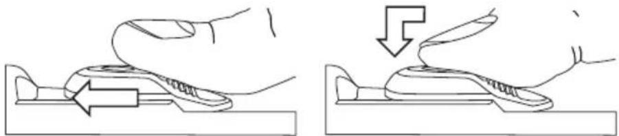
Illustration of a hand pressing down on a mechanical component, showing two states of force or movement (no text or symbols present)På: Skyv strømbryteren (4) framover for å skru på vinkelsliperen. Trykk inn den fremre delen på strømbryteren hvis du vil låse den i ON-modus.

natural_image
Two-step diagram showing a mechanical assembly with a downward arrow indicating motion (no text or symbols)natural_image
Symbol of a trash bin crossed with no visible text or labelsSpesifikasjoner
Spenning 230–240 V, 50 Hz
Effekt 850 W
Turtall ubelastet 12000 o/min.
Skivediameter 125 mm
Hulldiameter 22,2 mm
Gjenger på spindel M14
natural_image
Line drawings of hands operating a mechanical device (no text or symbols present)natural_image
Pure mechanical assembly diagrams showing two cross-sectional views of a bolted joint (no text or symbols)Laikan suojus
natural_image
Line drawing of a hand operating a mechanical component with a wrench (no text or symbols)natural_image
Two-step diagram showing a hand pressing a component on a surface, with an arrow indicating the motion direction (no text or symbols present)natural_image
Two-step diagram showing a mechanical assembly with a downward arrow indicating motion (no text or symbols)natural_image
Technical line drawing of a mechanical component with labeled parts (Bild 1, Bild 2), no readable text or symbols beyond labels.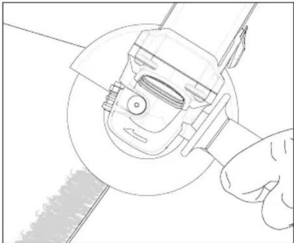
natural_image
Line drawing of a hand operating a mechanical tool with a circular component (no text or symbols)natural_image
Line drawings of hands using a mechanical tool to adjust a component (no text or symbols present)natural_image
Pure mechanical assembly diagram showing layered components without any text, numbers, or symbols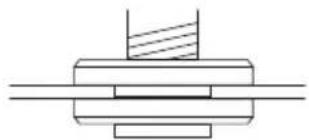
natural_image
Pure mechanical assembly diagram showing layered components without any text or symbolsnatural_image
Line drawing of a hand using a tool to adjust or install a mechanical component (no text or symbols present)Ein/Aus
natural_image
Line drawing of a hand pressing down on a mechanical component (no text or symbols)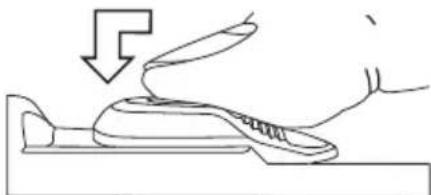
natural_image
Line drawing of a hand pressing down on a shoe component (no text or symbols)natural_image
Diagram of a hand using a tool to lift a component, showing a downward arrow (no text or symbols present)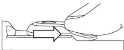
natural_image
Pure mechanical diagram showing a lever mechanism with no text or symbolsDeclaration of Conformity
Declares that this product complies with the requirements of the following directives and standards
Machinery Directive 2006/42/EC
EN 60745-1:2009
+A11:2010
EN 60745-2-3:2011
+A2:2013+A11:2014
+A12:2014
EMC Directive 2014/30/EU
EN 55014-1:2006
+A1:2009+A2:2011
EN 55014-2:2015
EN 61000-3-2:2006
+A1:2009+A2:2009
EN 61000-3-3:2013
Henrik Alfredsson
Manager Technique & Quality
Insjön, Sweden, 2017-01-31
CLAS OHLSON AB, SE-793 85 INSJÖN, SWEDEN
Sverige
Postal 10 - 13 Market Place
Kingston Upon Thames
Surrey
KT1 1JZ
Deutschland
Kundenservice Hotline: 040 2999 78111
E-Mail: kundenservice@clasohlson.de
Homepage
www.clasohlson.de


- Viktig information:
- Safety
- General Power Tool Safety Warnings – Personal Safety
- 1) Work area safety
- 2) Electrical safety
- 3) Personal safety
- 4) Power tool use and care
- 5) Service
- Special safety warnings applicable to grinding, dressing, brushing, or cutting
- Kickback
- Specific safety precautions for grinding and cutting with a cut-off wheel
- Additional safety precautions for cutting with a cut-off wheel
- Specific safety warnings for sanding
- Specific safety warnings for wire brushing
- Vibration
- Product safety symbols
- Product description
- Auxiliary handle
- Operating instructions
- Important:
- Fitting and removing discs
- Shatter guard
- Switching on/off
- Care and maintenance
- Troubleshooting guide
- Responsible disposal
- Specifications
- Vinkelslip
- På/av
- Specifikationer
- Sprengbeskyttelse
- Spesifikasjoner
- Laikan suojus
- Ein/Aus
- Declaration of Conformity
- Sverige
- Deutschland
Brand : Cocraft
Model : PRO A850-M
Category : Mill