
PRO Edition V40 - Lawn mower Cocraft - Free user manual and instructions
Find the device manual for free PRO Edition V40 Cocraft in PDF.


| Type | Cordless electric lawn mower |
| Model | PRO Edition V40 |
| Brand | Cocraft |
| Power Source | 40V lithium-ion battery |
| Cutting Width | 40 cm |
| Cutting Height Adjustment | 6 positions, 20-70 mm |
| Grass Collection Capacity | 50 L |
| Mulching Function | Yes, included |
| Side Discharge | Yes, optional |
| Weight | 18 kg |
| Dimensions (L x W x H) | 140 x 48 x 105 cm |
| Handle Type | Folding, ergonomic with soft grip |
| Motor Type | Brushless, high-torque |
| Grass Catcher Indicator | Yes, visual and audible |
| Safety Features | Blade brake, dual switch, overload protection |
| Maintenance | Periodic blade sharpening, battery care, cleaning |
| Spare Parts Availability | Blades, battery, wheels, grass catcher |
| Recommended Grass Height | Max 15 cm for best cut |
Frequently Asked Questions - PRO Edition V40 Cocraft
User questions about PRO Edition V40 Cocraft
0 question about this device. Answer the ones you know or ask your own.
Ask a new question about this device
Download the instructions for your Lawn mower in PDF format for free! Find your manual PRO Edition V40 - Cocraft and take your electronic device back in hand. On this page are published all the documents necessary for the use of your device. PRO Edition V40 by Cocraft.
USER MANUAL PRO Edition V40 Cocraft
Read the entire instruction manual carefully and make sure that you fully understand it before you use the equipment. Keep the manual for future reference.
Viktig information:
Please read the entire instruction manual before use and then save it for future reference. We reserve the right for any errors in text or images and any necessary changes made to technical data. In the event of technical problems or other queries, please contact our Customer Services.
Safety
Symbols marked on the product

Warning.

Read the entire instruction manual.
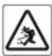
Objects ejected by the product can hit the operator or other persons in the vicinity and cause damage to property.
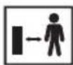
Keep bystanders at a safe distance from the working area.
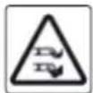
The blade rotates at high speed. Keep hands and feet away.
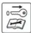
Turn off the lawnmower and remove the isolator key before making adjustments, cleaning or whenever leaving it unattended.

Do not use the lawnmower during rain or leave it outdoors exposed to rain.
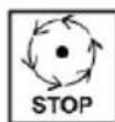
Always wait until the rotating parts of the lawnmower have come to a complete stop before attempting to touch them. The blades will continue to rotate for a time even after the motor has been turned off and can still cause possible injury.
Warning: Risk of injury due to electric shock.

Make sure to have good footing on slopes.
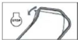
Release the safety handle to stop the lawnmower.

Warning: Keep hands and feet out of the cutting zone.
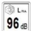
Guaranteed noise level.

Cutting diameter.
Battery symbols
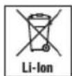


Never throw the battery in household waste, in fire or watercourses.

Charging indicator.

Do not expose the battery to strong sunlight for extended periods and never place it on a radiator (max temp. 45 °C).

Take the battery to a battery recycling centre as they will ensure that it is disposed of in an environmentally sound manner.

Read the instruction manual carefully before you charge the battery.

Do not expose the battery to rain or moisture.
Symbols marked on the charger

Warning.

Read the entire instruction manual.

Only use the battery charger indoors in a dry environment.

Protection class II product.
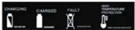
Charging indicator.
Guide to symbols on the grass collector
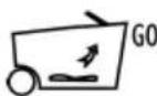
Grass level indicator raised: The grass collector is empty.
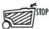
Grass level indicator lowered: The grass collector is full.
Guide to instruction manual symbols

Warning: warning for a possible hazard which could lead to serious personal injury and/or damage to the product and property if the written instructions are not followed.
Important: warning for a possible hazard which may lead to minor or moderate personal injury and/or damage to the product if the written instructions are not followed.

Note: Indicates important information or advice for optimum operation.

Remove the isolator key.
Safety instructions
- Read carefully through the instructions and familiarise yourself with all the controls and functions.
- Never let children or others who do not have adequate knowledge of these instructions use the product. Local regulations may restrict the age of the operator.
- Never let children play with the product. Cleaning and user maintenance shall not be done by children without adult supervision.
- Never use the mower close to other people and pay special attention to the presence of children and animals.
- Bear in mind that the operator is ultimately responsible for any accidents or hazards occurring to other people or their property.
- While mowing, always wear substantial footwear and long trousers. Do not operate the lawnmower when barefoot or wearing open sandals. Avoid wearing loose clothing which can get caught in the rotating parts of the lawnmower.
- Make sure that the area being cut is free from loose and foreign objects. Thoroughly inspect the area to be mowed and remove all objects which could be thrown (stones, branches, etc.) before mowing.
- Before operating, always visually inspect to ensure that the blades and blade bolts are not worn or damaged. Replace worn or damaged blades and bolts in sets to preserve balance. Replace damaged or unreadable rating plates or labels.
- Only mow in daylight or in good lighting conditions.
- Avoid cutting wet grass.
- Walk, never run with the mower.
- Cut along the face of slopes, never up and down.
- Use extreme caution when turning and changing direction on slopes.
• Always be extra careful when backing or pulling the mower towards yourself. - Turn off the mower when you need to drive it over other surfaces than grass.
- Never operate the mower with defective guards, or without safety devices such as deflectors or grass catchers in place.
- Take care and follow the instructions when you start the mower. Make sure your feet are at a safe distance from the blades.
- Do not tilt the mower so that many wheels leave the ground unless absolutely necessary when turning it on, such as when the grass is very high. In this case do not tilt the mower more than necessary to start the motor and only tilt the section facing away from the user.
- Do not start the mower if you are standing in front of the discharge chute.
- Make sure to keep hands and feet away from rotating parts. Never stand in front of the discharge chute.
- Never lift or carry the mower when the motor is on.
- Turn off the motor, remove the safety key and wait until the rotating parts have stopped completely if:
- you leave the mower unattended.
- the discharge chute is blocked and needs to be cleaned.
- you need to clean, service or carry out other maintenance.
- you have mowed over a foreign object or the mower starts vibrating. Carefully inspect the mower in case of damage and repair if necessary before the mower can be turned on.
- Regularly check that all nuts, bolts and screws are tight to ensure that the product is safe to use.
- Check the grass collector regularly for wear and tear and damage.
- If the mower has several blades, bear in mind that if you rotate one blade manually the other blades can also start moving.
- Take care when you are making adjustments or service so that your fingers don't get caught between the blades and other parts of the mower.
- Let the product cool completely before putting it away for storage.
- During service, maintenance and repair bear in mind that the blades can continue to rotate even when the motor is switched off.
- For safety reasons replace worn and damaged parts. Only use original spare parts and accessories.
General safety instructions for batteries and chargers
- Always be careful of inadvertent starts while attaching the battery to the mower. Make sure that the isolator key is removed before connecting the battery to the mower. The mower battery must only be charged indoors in dry areas.
- Only use the included battery charger or a charger recommended by the manufacturer. The battery charger is only designed to charge certain types of batteries. If a charger designed for another type of battery is used the risk for fire, personal injury or explosion is significantly increased.
- Only use the included battery or a battery recommended by the manufacturer. Use of any other types of batteries can lead to fire and/or bodily injury.
- Make sure that the charger and its air vents are clean and unblocked.
- Check that the charger, its mains lead and plug are whole and damage-free. Never use the charger if it has been damaged in any way.
- Keep unused batteries a safe distance away from paper clips, coins, keys, screws and other metal objects that could potentially short-circuit the battery terminals. Short-circuiting the battery terminals can lead to fire or explosion.
- Never attempt to repair the charger yourself. All repairs must only be carried out by qualified technicians. A damaged charger or parts of it poses a risk for electric shock.
-
Never use the battery charger or batteries in environments where flammable liquids or gases are stored. The charger becomes warm during use and can therefore pose a potential fire hazard.
-
Do not try to dismantle the battery. Doing so poses a risk for short-circuiting.
- Do not expose the battery to heat, such as leaving it in direct sunlight or disposing of it in fire. Risk of explosion.
- Mistreatment or a defective battery may cause gas to leak from the battery. Always ensure adequate ventilation. The battery fumes are irritating to the respiratory tract.
- The battery must not be exposed to moisture or water. Risk of an electric shock.
- The battery can become hot after a longer period of use. Let it cool before attempting to recharge it.
- Never attempt to open the battery casing.
- Never store a battery in direct sunlight or at temperatures above 45 °C.
- Only charge the battery when the ambient temperature is between 10^ and 40^ .
- Never expose the battery or the charger to water.
- Keep the charger and batteries out of the reach of children.
- Always transport batteries in a safe manner ensuring that they do not come into contact with each other and never in a metal container.
- Charge the battery completely if it is not to be used for an extended period.
- Store the battery at a temperature of 0–45 °C. It should never be left in a hot, sun-exposed car.
- Battery fluid can leak from the battery if it is damaged. Avoid physical contact with this fluid. If this fluid comes into contact with skin; rinse the area thoroughly with water. If the fluid comes into contact with the eyes, seek medical attention immediately. Fluid which has leaked from a battery pack can cause skin irritation or burns.
- The battery must only be charged with a charger that conforms to EN60335-2-29 standards.
Product description
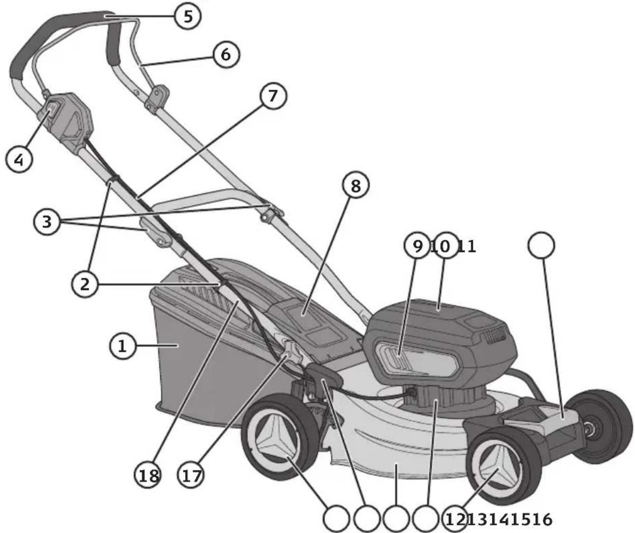
- Collector
- Cable holder
- Quick-release clamp for folding the upper handle up/down
- Safety switch
- Upper handle
- Safety handle
- Electrical cable
- Discharge chute hatch
- Ventilation opening
- Lid of battery and isolator key compartment
- Carrying handle
- Front wheel
- Motor
- Cover
- Cutting height adjustment lever
- Rear wheel
- Handle locking knob
- Lower handle
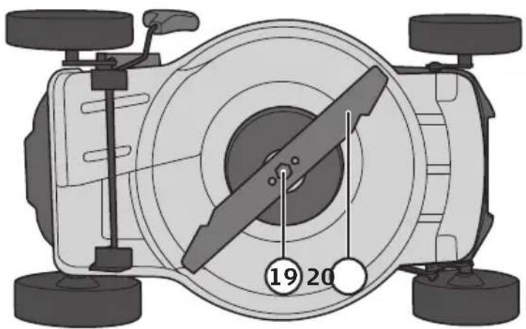
- Blade bolt
- Blade
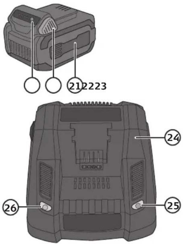
- Battery (one battery included, extra batteries sold separately)
- Release latch
- Battery charge status
- Charger
- Charging indicator
- Power/full-charge indicator
- Isolator key
- Battery compartment × 2
Assembly Handle
- Push the ends of the lower handle (18) towards the brackets (A) on the back of the mower. Make sure to put the bracket pin (B) in the round hole down on the end of the handle.
- Push the coach bolt (C) into the square hole (D) from the inside and screw on the locking knob (17) from the outside.

Important
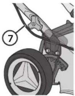
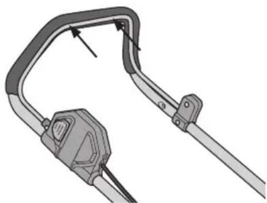
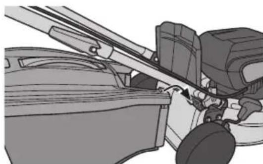
Make sure that the electrical cable (7) is lying along the outside of the lower handle.
natural_image
Mechanical assembly diagram showing a wheel and attached components with numbered callouts (no text or symbols present)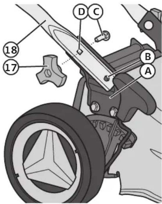
natural_image
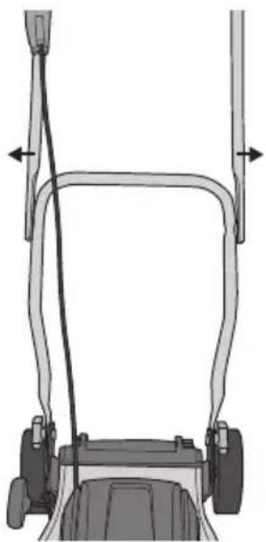
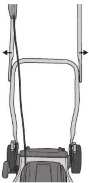
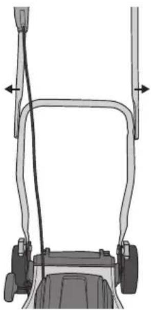
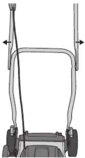
Technical line drawing of a lawn mower frame with guide rails and support legs (no text or symbols)- Place the ends of the upper handle along the sides of the lower handle. If you apply slight pressure this makes it easier to press the ends outwards.
natural_image
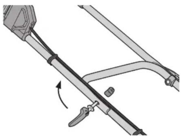
Mechanical assembly diagram showing a lever mechanism with a curved bracket and directional arrow (no text or symbols)- Push the threaded end of the quick-release clamp (3) through the hole from the outer side of the handle and screw it onto the nut. Note: Turn the nut so that its concave seat mates with the tube of the handle.

Important
The electric cable and control switch should be on the right-hand side of the mower.
natural_image
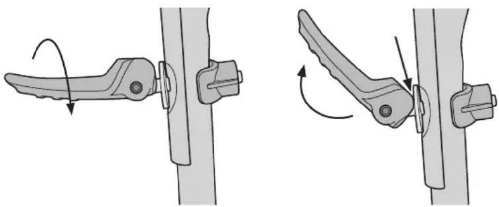
Mechanical linkage diagram showing two configurations of a lever mechanism (no text or labels)- Screw in the quick-release clamp lever a few turns and test the tightness of the quick-release clamp. The clamp is set correctly when the cam lever touches the washer when it is halfway in towards the tube.
- If it is too difficult to squeeze the quick-release clamp lever down, you should unscrew the lever.
- If you don't notice any resistance and the lever is loose against the washer, screw the lever in more tightly.
natural_image
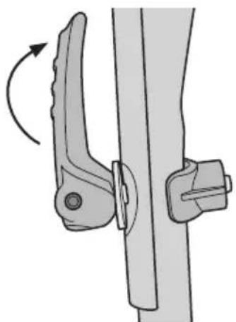
Mechanical clamp mechanism diagram showing rotational motion (no text or symbols)- Push the lever tightly against the tube.
natural_image
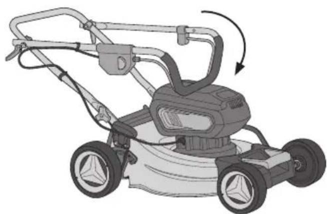
Illustration of a lawn mower with a rotating blade and handle (no text or symbols)- Undo the quick-release clamps and fold the upper handle forwards to make the lawnmower smaller and easier to store.
Battery
Inserting and removing the battery
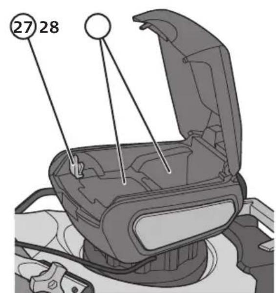
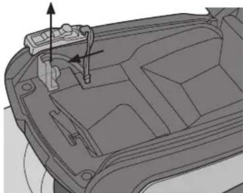
- Lift the battery compartment lid (10).
natural_image
Technical line drawing of a mechanical component with internal parts and mounting holes (no text or symbols)- Press down the isolator key (27) lock button to release and remove it.
natural_image
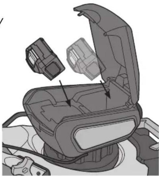
Mechanical assembly diagram showing a device with open lid and internal components (no text or symbols)- Slide the battery (21) into the battery holder and push down as far as it goes. You will first hear a click, when the battery crosses the latch and another click when the latch locks the battery securely in place.
Information: It is possible to use two batteries at the same time (additional battery sold separately). Using two batteries will double the operating time.
- Press the battery release catch and pull the battery upwards to remove it.
Grass collector
natural_image
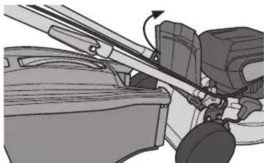
Mechanical assembly diagram showing a lever mechanism with rotating components (no text or symbols)- Fold up the discharge chute hatch (8) and keep it in the open position.
natural_image
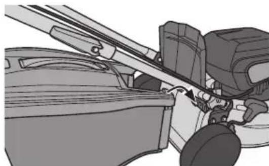
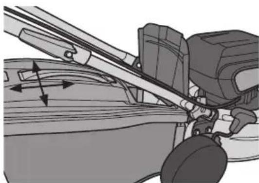
Mechanical assembly diagram showing a lever mechanism with no visible text or symbols- Align the slots in the corners of the collector with the hooks at the base of the collector lid.
natural_image
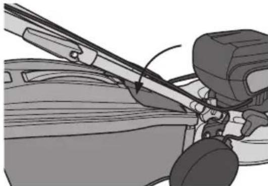
Mechanical assembly diagram showing a lever mechanism with directional arrows indicating motion (no text or symbols present)- Hook the collector on, check that it is sits securely.
natural_image
Mechanical assembly diagram showing a lever mechanism with a person operating the wheel (no text or symbols visible)- Close the hatch.
Setting the cutting height

Warning
Always turn off the mower and let the rotating blade come to a complete stop before adjusting the cutting height.

Information
- Adjust cutting height in relation to grass height. Start with a high cutting height and adjust accordingly for the best results.
- When cutting grass for the first time at the beginning of the season, the mower should be set to a rather high setting in relation to grass height in order to ensure proper healthy growth of your lawn. Thereafter, cutting height can be adjusted according to need. Remember that cutting longer grass will shorten the battery operating time.
There are 6 cutting height settings:
-
25 ~mm
-
55 mm
-
35 ~mm
-
65 mm
-
45 ~mm
-
75 mm
-
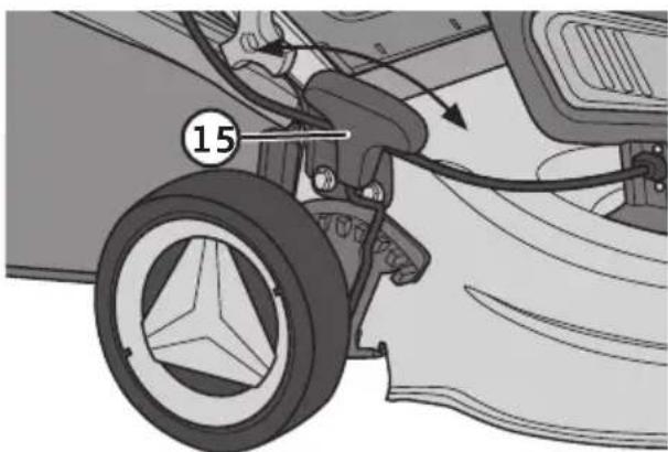
Pull the height lever (15) towards yourself/away from the cover and move the lever
- to the left/backwards to raise or - to the right/forwards to lower the cutting height.
- Release the lever at the desired position and make sure that it sits securely in the notch.
natural_image
Mechanical diagram showing a car's wheel and suspension components with numbered annotation (15), no readable text or symbols present.Instructions for use

Important
This mower is only constructed to be used on residential domestic lawns. Use of the product for a purpose other than that for which it was intended could result in an injury or damage to property.
Battery
Charging the battery
Temperature range for charging and storing the battery: 0–40 °C.
-
Plug the charger (24) into a wall socket. The indicator (26) will shine green to indicate that the charger is receiving power from the mains.
-
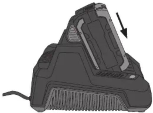
Insert the battery into the charger, making sure that it clicks into place.
-
The charging indicator (25) shines red when charging is in progress.
- The charging indicator (25) goes out and the full charge indicator (26) shines green when the battery is fully charged.
natural_image
3D rendering of a mechanical device with a downward arrow indicating a component (no text or symbols visible)- Press in the lock buttons (22) on the battery and remove it from the charger when it is fully charged.
- Unplug the charger from the wall socket when it is not in use.
Battery charge status indication
Press in the red button on the battery to check the charge status. If all the green lights come on the battery is fully charged. If only one green indicator comes on, the battery is discharged and needs to be charged before you can use it.
Note:
- The lithium-ion battery has a built-in electronic deep discharge protection which prevents partial power from being delivered. Full power is provided at all times until the electronic protection engages, turning off the lawnmower and signifying that the battery needs to be recharged. Do not continue work after this point, as doing so may damage the battery. A battery recharge is now required before any work is resumed.
- The battery also has a built-in electronic overload protection. If the lawnmower is put under too much load, the electronics automatically cut the power and the lawnmower will stop. Release the safety handle and wait a few seconds before switching the lawnmower on again.
- The lithium-ion battery has no memory which means that it can be charged at any time regardless of battery level.
- Charge the battery for at least 6 hours the first and second time it is charged.
- For long-term storage the battery should be fully charged at least every 6 months.
Switching on and off

Warning
- Start the mower only when your hands and feet are a safe distance from the rotating blade.
-
The blade will continue to rotate a short while after the motor has been turned off. Always let the motor/blade come to a complete stop before starting the motor again.
-
Insert the battery.
- Insert the isolator key.
natural_image
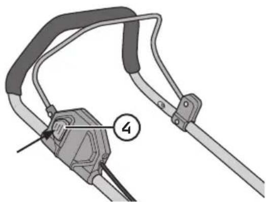
Diagram of a cable clamp with a numbered component (4) and no visible text or symbols- Press the safety lock button (4) and keep it pressed in.
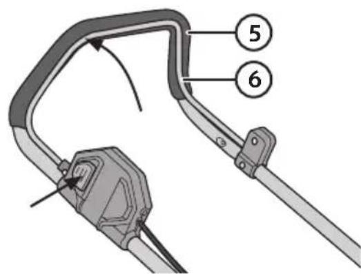
- Pull the safety handle (6) completely towards the upper handle (5).
natural_image
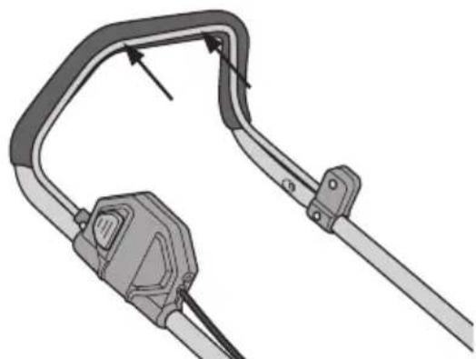
Diagram of a cable clamp with a handle and connector (no text or symbols)- Release the lock-off switch and hold in the safety handle with both hands while you are mowing.
natural_image
Diagram of a mechanical device with lever and handle, showing motion direction (no text or symbols)-
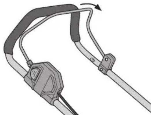
Release the safety handle to turn off the lawnmower.
-
Remove the isolator key.
Care and maintenance

Warning
- Always use original parts. Non-original parts can present a risk for injury even if they should fit the mower.
- Always make sure the isolator key and battery are removed from the mower before starting maintenance or servicing.
Cleaning
- Clean the mower with a brush or cloth after each use. Use only mild cleaning agents, never solvents or corrosive chemicals.
- Never use water to wash off the mower as you can damage the electrical equipment.
Changing blades

Warning
Always use work gloves when holding the blade as it is sharp.
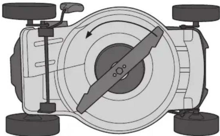
- Turn the mower on one side to inspect the blade (20). If the blade is blunt or damaged it should be replaced.
- Hold the blade and loosen the bolt (19) using a 16 mm spanner or socket (sold separately).
- Remove the blade from the retaining pins. Clean if necessary.
- Push the new blade onto the spindle, make sure it is the right way up and tighten the bolt.
natural_image
Top-down schematic of a vehicle showing steering wheel, wheels, and directional arrow (no text or symbols)Storage
If the mower is to be stored for an extended period, during winter for example, the following steps should be followed:
- Clean the mower thoroughly.
- Inspect the entire mower for possible damage.
- Store the mower in a clean and dry environment.
- Charge the battery.
Troubleshooting
The problems described below can often be addressed by the user. If there is any doubt, contact Customer Services.
| Problem Solution | |
| Motor does not start. | Make sure the isolator key is correctly inserted.Make sure the battery is correctly inserted.Incorrect starting procedure. First press and hold the safety button and then clasp the safety handle against the upper handle. |
| Motor stops suddenly. | The overload protection has tripped. Let the motor cool down.Increase cutting height.The battery is either too warm or too cold. Let the battery attain normal room temperature. |
| Mower vibrates during use. | Make sure there are no loose parts.The blade is damaged. Replace it.Make sure that the blade or its bolt is not loose. |
| Unsatisfactory cutting results. | The blade is damaged or blunt. Replace it.The collector is full.Make sure that the collector is not clogged.The wrong cutting height has been set. Adjust. |
| The battery cannot be charged. | The battery is defective and needs to be replaced.Make sure the battery and charger terminals are clean and free from dirt and debris.Make sure that the charger is correctly connected to the wall socket. |
| The battery goes flat after a short time. | The wrong cutting height has been set. Increase cutting height and push the mower a little slower.Wet grass. Let the grass dry.Thick grass. Increase cutting height and push the mower a little slower.Make sure the battery is not defective. |
Responsible disposal
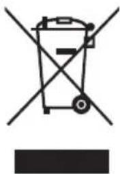
This symbol indicates that this product should not be disposed of with general household waste. This applies throughout the entire EU. In order to prevent any harm to the environment or health hazards caused by incorrect waste disposal, the product must be handed in for recycling so that the material can be disposed of in a responsible manner. When recycling the product, take it to your local collection facility or contact the place of purchase. They will ensure that the product is disposed of in an environmentally sound manner.
natural_image
Symbol of a trash bin with crossed lines indicating no waste or restriction, and a solid black rectangle below (no text or labels)Specifications
Lawnmower
Motor voltage 36 V
No-load speed 2800–3100 rpm
Motor Brushless
Cutting width 38 cm
Cutting heights Six (25/35/45/55/65/75 mm)
Protection class ||
IP rating IPX1
Sound pressure level LpA = 79.6 dB(A), K = 3 dB(A)
Sound power level LwA = 90.5 dB(A), K = 1.82 dB(A)
Guaranteed noise level 92 dB(A)
Vibration level 0.68 m/s², K = 1.5 m/s²
Wheels Plastic
Cover Steel
Grass collector 40 L
Weight 16.5 kg
Battery
Voltage 36 V
Capacity 2.5 Ah
Charging time 1 hour
Charger
Rated voltage 220–230 V, 50/60 Hz
Output voltage 36 V DC
Output current 3.6 A
Weight 750 g
Vibration
- The measurement of the vibration emission level (triaxial vector sum) and the noise level values declared in this instruction manual have been carried out in accordance with a standardised test method described in EN 50636-2-91 and can be used for comparing one power tool with another.
- The measurement method may also be used for a preliminary assessment of vibration exposure.
- The declared vibration emission level applies when the power tool is used in accordance with this instruction manual. If however, the power tool is used for other purposes and with other accessories or has not been properly maintained, the vibration emission level could increase significantly over the total working period.
- For an exact assessment of the vibration exposure, the times when the tool is switched off or running idle should also be taken into account. This significantly reduces the vibration exposure over the total working period. Decide upon safety measures to protect the operator from the effects of vibration during all types of use.
Gräsklippare Cocraft Pro 36 V
Art.nr 31-5098 Modell ALR-2R3-380-S
natural_image
Mechanical assembly diagram showing a wheel and attached components with numbered label (7), no readable text or symbols present.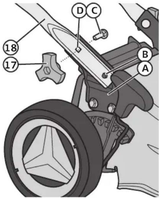
natural_image
Technical line drawing of a lawn mower with adjustable arms and legs (no text or symbols)natural_image
Mechanical assembly diagram showing a lever mechanism with a curved guide and pivot point (no text or symbols)natural_image
Mechanical linkage diagram showing two configurations of a lever mechanism (no text or labels)natural_image
Illustration of a lawn mower and its side-mounted lawn tool (no text or symbols present)natural_image
Technical diagram of a vehicle engine compartment showing internal components and alignment arrows (no text or labels)natural_image
Technical illustration of a mechanical device with open lid and internal components (no text or symbols)natural_image
Mechanical assembly diagram showing a lever mechanism with rotating components (no text or symbols)natural_image
Mechanical assembly diagram showing a lever mechanism with no visible text or symbolsnatural_image
Mechanical assembly diagram showing a lever mechanism with motion arrows (no text or symbols)natural_image
Mechanical assembly diagram showing a lever mechanism with a belt and guide (no text or symbols)natural_image
Mechanical diagram showing a car wheel with attached components and a numbered label (15), no readable text or symbols present.Användning

Viktigt!
natural_image
3D rendering of a hairless vacuum cleaner with a black outline and arrow indicating the component (no text or symbols)Start och stopp

Varning!
- Dra in säkerhetshandtaget (6) helt mot det övre handtaget (5).
natural_image
Diagram of a cable clamp device with a handle and connector (no text or symbols)natural_image
Diagram of a mechanical device with lever and handle, showing motion direction (no text or symbols)natural_image
Top-down schematic of a vehicle's front wheel assembly with four wheels and a central blade (no text or symbols)Förvaring
natural_image
Symbol of a trash bin crossed with no visible text or labelsSpecifikationer
Gräsklippare
Motorspänning 36 V
Varvtal 2800–3100 varv/min
Motor Borstlös
Klippbredd 38 cm
natural_image
Mechanical assembly diagram showing a wheel and attached components (no text or symbols visible)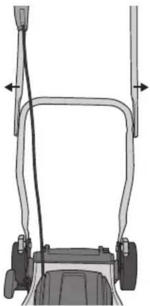
natural_image
Diagram of a lawn mower frame with attached guide rails and wheel (no text or symbols)natural_image
Mechanical assembly diagram showing a lever mechanism with a curved bracket and directional arrow (no text or symbols)natural_image
Mechanical lever mechanism diagram showing a curved arrow indicating motion (no text or symbols present)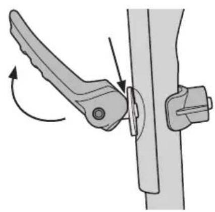
natural_image
Mechanical lever mechanism diagram showing pivot point and adjustment arrows (no text or symbols)natural_image
Mechanical diagram showing a lever mechanism with an arrow indicating rotational motion (no text or symbols present)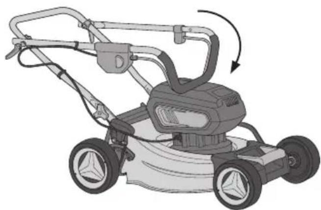
natural_image
Illustration of a lawn mower with a curved arrow indicating rotational motion (no text or symbols)natural_image
Technical line drawing of a mechanical component with internal parts and directional arrows (no text or symbols)natural_image
Technical illustration of a mechanical device with open lid and internal components (no text or symbols)natural_image
Mechanical assembly diagram showing a lever mechanism with no visible text or symbols- Slå opp utkastlokket (8) og hold det i denne stillingen.
natural_image
Mechanical assembly diagram showing a lever mechanism with no visible text or symbolsnatural_image
Mechanical assembly diagram showing a lever mechanism with no visible text or symbolsnatural_image
Mechanical assembly diagram showing a lever mechanism with a belt and guide (no text or symbols)- Slipp ned utkastlokket.
natural_image
Mechanical assembly diagram showing a car wheel with attached components and a numbered label (15), no readable text or symbols present.Bruk

Viktig!
Denne gressklipperen er konstruert til klipping av gressplener i private hager. Annen bruk enn det den er beregnet på kan føre til personskader eller skade på gjenstander.
Batteri
Lading av batteri
natural_image
3D rendering of a mechanical device with a downward arrow indicating a component (no text or symbols visible)natural_image
Technical illustration of a mechanical device with a handle and lever mechanism (no text or symbols)natural_image
Diagram of a mechanical device with lever and handle, showing motion direction (no text or symbols)natural_image
Top-down schematic of a vehicle's front wheel assembly showing steering wheel, drivetrain, and four wheels (no text or labels)Oppbevaring
natural_image
Symbol of a trash bin crossed with no text or numbers, representing waste sorting or disposal (no text present)Spesifikasjoner
Gressklipper
Motorspenning 36 V
Turtall 2800–3100 o/min
Motor Børsteløs
Klippebredde 38 cm
natural_image
Mechanical assembly diagram showing a wheel and attached components with numbered label (7), no readable text or symbols present.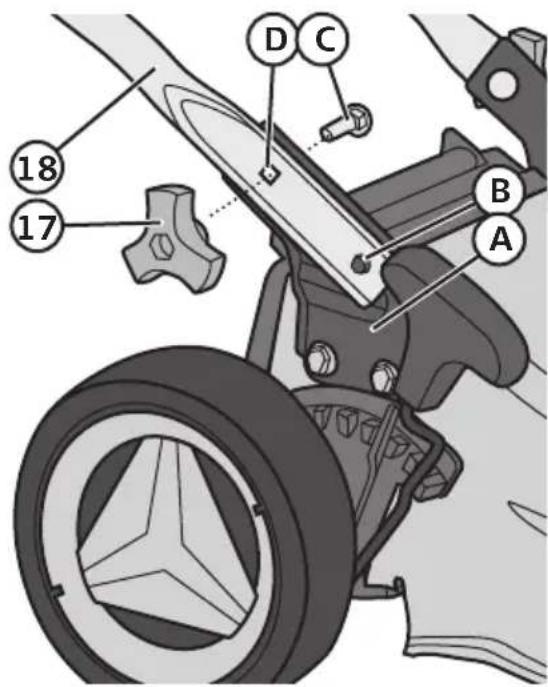
natural_image
Technical line drawing of a lawn mower with adjustable arm and legs (no text or symbols)natural_image
Mechanical assembly diagram showing a lever mechanism with a curved guide and pivot point (no text or symbols)natural_image
Mechanical clamp mechanism diagram showing rotational motion (no text or symbols)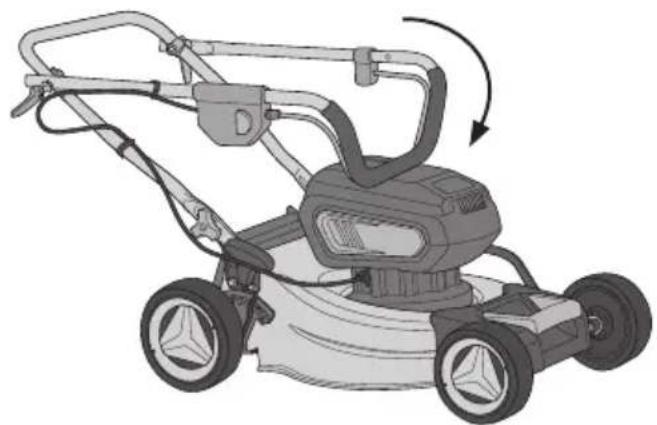
natural_image
Illustration of a lawn mower with a rotating blade and handle (no text or symbols)natural_image
Technical illustration of a mechanical component with internal parts and mounting features (no text or symbols)natural_image
Mechanical assembly diagram showing a device with open lid and internal components (no text or symbols)natural_image
Mechanical assembly diagram showing a lever mechanism with no visible text or symbolsnatural_image
Mechanical assembly diagram showing a vehicle's suspension system with no visible text or symbolsnatural_image
Mechanical assembly diagram showing a lever mechanism with no visible text or symbolsnatural_image
Mechanical assembly diagram showing a lever mechanism with a belt and guide (no text or symbols)natural_image
Mechanical assembly diagram showing a car wheel with attached components and a numbered label (15), no readable text or symbols present.Käyttö
△ Huom.!
natural_image
Diagram of a hairdryer with a black arrow indicating the blade (no text or symbols present)natural_image
Diagram of a cable clamp device with a handle and connector (no text or symbols)natural_image
Diagram of a mechanical device with lever and handle, showing motion direction (no text or symbols)natural_image
Top-down schematic of a vehicle's front wheel assembly showing steering wheel, wheels, and wheel rim (no text or labels)Säilytys
natural_image
Mechanical assembly diagram showing a wheel and attached components (no text or symbols)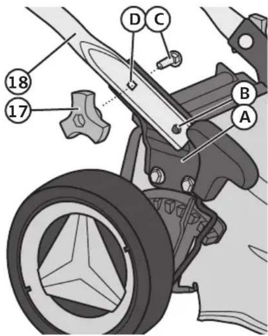
natural_image
Technical line drawing of a lawn mower with handle and wheels (no text or symbols)natural_image
Mechanical assembly diagram showing a lever mechanism with a curved bracket and directional arrow (no text or symbols)natural_image
Mechanical lever mechanism diagram showing a curved arrow indicating motion (no text or symbols present)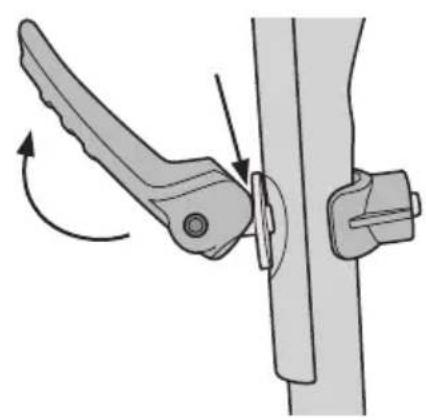
natural_image
Mechanical lever mechanism diagram showing pivot point and adjustment arrows (no text or symbols)natural_image
Mechanical diagram showing a lever mechanism with an arrow indicating rotational motion (no text or symbols present)natural_image
Illustration of a lawn mower with a rotating handle and side blades (no text or symbols)natural_image
Technical illustration of a mechanical component with internal parts and mounting features (no text or symbols)natural_image
Exploded view diagram of a mechanical device showing internal components and part assembly (no text or labels)natural_image
Mechanical assembly diagram showing a lever mechanism with no visible text or symbolsnatural_image
Mechanical assembly diagram showing a lever mechanism with no visible text or symbolsnatural_image
Mechanical assembly diagram showing a lever mechanism with motion arrows (no text or symbols)natural_image
Mechanical assembly diagram showing a lever mechanism with a head-mounted component (no text or symbols visible)natural_image
Diagram of a mechanical device with labeled parts, showing a handle and cable assembly (no text or symbols present)natural_image
Technical illustration of a mechanical device with a handle and lever mechanism (no text or symbols)natural_image
Diagram of a mechanical device with lever and handle, showing motion direction (no text or symbols)natural_image
Top-down schematic of a vehicle's front wheel and dashboard assembly (no text or symbols)Aufbewahrung
natural_image
Symbol of a waste bin with no text or labels, crossed by two diagonal lines and a solid rectangle below (no text or symbols present)Technische Daten
Rasenmäher
Motorspannung 36 V
Declaration of Conformity
Declares that this product complies with the requirements of the following directives and standards
Machinery Directive 2006/42/EC
EMC Directive 2014/30/EU
EN 60335-1:2012
+A11:2014
EN60335-2-77:2010
EN: 55014-1: 2006
+A2: 2011
EN: 55014-2: 2015
Henrik Alfredsson
Technical Manager
Insjön, Sweden, 2018-01-25
CLAS OHLSON AB, SE-793 85 INSJÖN, SWEDEN
Sverige
Postal 10 - 13 Market Place
Kingston Upon Thames
Surrey
KT1 1JZ
Deutschland
Kundenservice Hotline: 040 2999 78111
E-Mail: kundenservice@clasohlson.de
Homepage
www.clasohlson.de


- Viktig information:
- Safety
- Symbols marked on the product
- Battery symbols
- Symbols marked on the charger
- Guide to symbols on the grass collector
- Guide to instruction manual symbols
- Safety instructions
- General safety instructions for batteries and chargers
- Product description
- Assembly Handle
- Important
- Battery
- Inserting and removing the battery
- Grass collector
- Setting the cutting height
- Warning
- Information
- Instructions for use
- Charging the battery
- Battery charge status indication
- Note:
- Switching on and off
- Care and maintenance
- Cleaning
- Changing blades
- Storage
- Troubleshooting
- Responsible disposal
- Specifications
- Lawnmower
- Charger
- Vibration
- Gräsklippare Cocraft Pro 36 V
- Användning
- Viktigt!
- Start och stopp
- Varning!
- Förvaring
- Specifikationer
- Gräsklippare
- Bruk
- Viktig!
- Batteri
- Lading av batteri
- Oppbevaring
- Spesifikasjoner
- Gressklipper
- Käyttö
- △ Huom.!
- Säilytys
- Aufbewahrung
- Technische Daten
- Rasenmäher
- Declaration of Conformity
- Sverige
- Deutschland
Brand : Cocraft
Model : PRO Edition V40
Category : Lawn mower