
GBK100LN - Air-conditioner GORENJE - Free user manual and instructions
Find the device manual for free GBK100LN GORENJE in PDF.

| Product Type | Combined (Electric and Auxiliary Heating) Water Heater |
| Model | GBK100LN |
| Volume | 100 L |
| Rated Pressure | 0.6 MPa |
| Empty Weight | 56 kg |
| Filled Weight | 156 kg |
| Power Supply | 230 V~, 2000 W |
| Heating Element | Dual 1000 W immersion heaters |
| Protection Class | I |
| Degree of Protection | IP25 |
| Heating Time to 75°C (15°C inlet) | 3 h 55 min |
| Mixed Water at 40°C | 189 L |
| Standby Energy Consumption | 1.58 kWh/24h |
| Heat Exchanger Surface | 0.88 m² |
| Heat Flow of Heat Exchanger | 17600 W |
| Temperature Setting Range | 25°C to 75°C |
| Anti-corrosion Protection | Enameled tank with magnesium anode |
| Installation | Wall-mounted, upright position only |
| Water Connections | Cold inlet: G3/4; Hot outlet: G1/2 |
| Return Pipe Connection | Top inlet for instant hot water circulation |
| Safety Devices | Safety valve, non-return valve, bimetal fuse |
| Cleaning | With mild detergent; avoid abrasives |
| Maintenance Interval | Every 2 years by authorized service |
Frequently Asked Questions - GBK100LN GORENJE
User questions about GBK100LN GORENJE
0 question about this device. Answer the ones you know or ask your own.
Ask a new question about this device
Download the instructions for your Air-conditioner in PDF format for free! Find your manual GBK100LN - GORENJE and take your electronic device back in hand. On this page are published all the documents necessary for the use of your device. GBK100LN by GORENJE.
USER MANUAL GBK100LN GORENJE
natural_image
White cylindrical water heater with control panel and dial indicator (no visible text or symbols on body)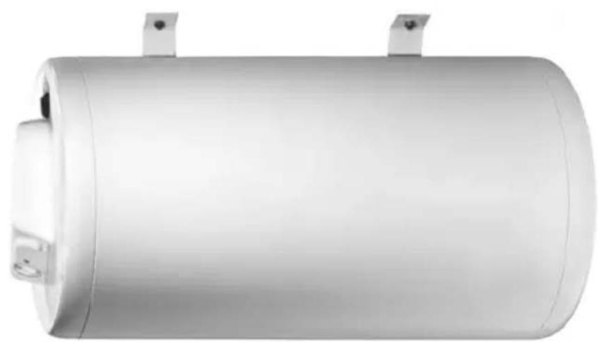
natural_image
Exterior view of a cylindrical metallic cylindrical device with mounting brackets (no text or symbols visible)GBL
Instructions for Use 15
Upute za upotrebu 19
Návod k obsluze 23
Dear customer, we thank you for purchasing our product.
PLEASE READ THE INSTRUCTIONS THOROUGHLY PRIOR TO THE INSTALLATION AND FIRST OPERATION OF THE WATER HEATER.
THIS APPLIANCE IS NOT INTENDED FOR USE BY PERSONS (INCLUDING CHILDREN) WITH REDUCED PHYSICAL, SENSORY OR MENTAL CAPABILITIES, OR LACK OF EXPERIENCE AND KNOWLEDGE, UNLESS THEY HAVE BEEN GIVEN SUPERVISION OR INSTRUCTION CONCERNING USE OF THE APPLIANCE BY PERSON RESPONSIBLE FOR THEIR SAFETY.
CHILDREN SHOULD BE SUPERVISED TO ENSURE THAT THEY DO NOT PLAY WITH THE APPLIANCE.
This water heater has been manufactured in compliance with the relevant standards and tested by the relevant authorities as indicated by the Safety Certificate and the Electromagnetic Compatibility Certificate. Its basic technical properties are stated upon the nameplate, glued between the connection pipes. The water heater may be connected to water and electric power supply only by a qualified specialist. The reach in its inside due to the repair or removal of limestone and checking and replacement of anti-corrosion protection anode may be performed only by an authorised service workshop.
INSTALLATION
The water heater shall be built as close as possible to the outlets. It has to be fitted to the wall using appropriate rag bolts with minimum diameter of 8 mm. In case the wall in question cannot support the weight three times that of the water heater filled with water, the relevant section of the wall where the heater is to be installed, must be suitably reinforced. GBK water heater must be mounted to the wall in the upright position. Only GBL 50 and GRL 80 models may be mounted horizontally to the ceiling. These water heaters may not be wall- or floor-mounted as this could damage the heaters.
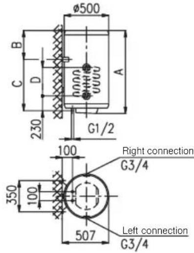
TECHNICAL CHARACTERISTICS OF WATER HEATER
| Type | GBL 50 GBL 80 GBK 80 L/D GBK 100 L/D GBK 120 L/D GBK 150 L/D GBK 200 L/D | ||||||
| Model | GBL 50 N | GBL 80 N | GBK 80 LN/RN | GBK 100 LN/RN | GBK 120 LN/RN | GBK 150 LN/RN | GBK 200 LN/RN |
| Volume [l] | 50 | 80 | 80 | 100 | 120 | 150 | 200 |
| Rated pressure [MPa] | 0,6 | ||||||
| Weight / Filled with water [kg] | 27/77 | 33/113 | 51/131 | 56/156 | 62/182 | 72/222 | 90/290 |
| Anti-corrosion protection of tank | Emailed & Mg Anode | ||||||
| Power of electrical heater [W] | 2000 | ||||||
| Connection voltage [V~] | 230 | ||||||
| Protection class | I | ||||||
| Degree of protection | IP 25 | ||||||
| Heating time to 75°C ^1) [h] | 1^55 | 3^05 | 3^05 | 3^55 | 4^35 | 5^45 | 7^40 |
| Quantity of mixed water at 40° [l] | 80 | 117 | 151 | 189 | 226 | 276 | 360 |
| Energy consumption [kWh/24h] | 1,20 | 1,46 | 1,39 | 1,58 | 1,77 | 2,05 | 2,50 |
1) Time required for the electric heating element to heat the entire tank volume, at the water supply temperature of 15°C.
2) Power consumption required for the temperature of water in the water heater to be maintained at 65^ C, at the room temperature of 20^ C, measured in accordance with the DIN 44532 standard.
| GBK 80 L/D | GBK100 L/D | GBK | 120 L/D | GBK 150 | L/D | GBK 200 L/D | ||
| Nominal pressure | [MPa] | 0,6 | ||||||
| Max. inlet temperature of heating medium | [°C] | 85 | ||||||
| Surface of transmitter | [m2] | 0,72 | 0,88 | |||||
| Heat flow of heat transmitter^3) | [W] | 14400 | 17600 | |||||
3) Heating medium: inlet temperature 70°C, flow 3000 l/h.
Sanitary water: inlet temperature 10°C, outlet temperature 45°C, flow 437 l/h.
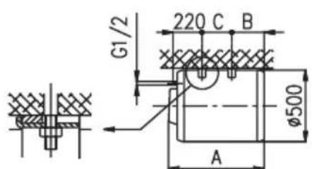
| GBL 50 G | BL 80 GBK 8 | 0 GBK 100 GB | BK 120 GBK | 150 GBK 200 | |||
| A 58 | 3 803 803 9 | 48 1103 13 | 8 1510 | ||||
| B 18 | 7 207 207 2 | 202 207 222 | 430 | ||||
| C 14 | 5 345 565 7 | 15 865 106 | 5 1050 | ||||
| D | 340 | 416 | 416 | 416 | 416 |
Connection and installation dimensions [mm].
GBK 80 - 200
GBL 50-80
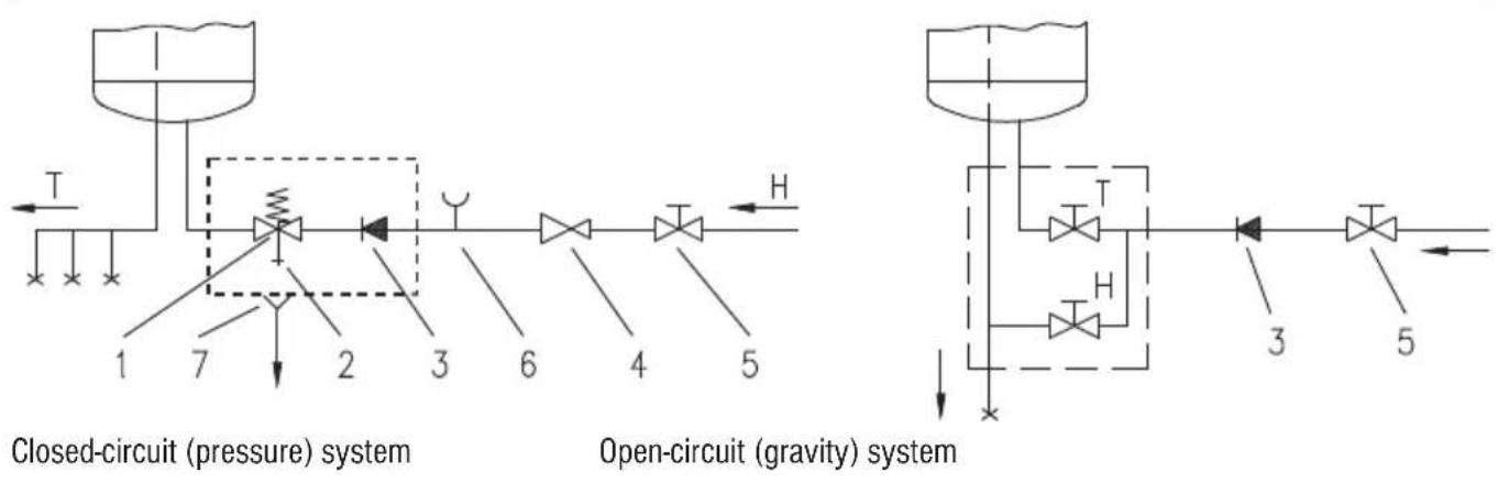
CONNECTION TO THE WATER SUPPLY SYSTEM
Inlet and outlet of water are on the water heater pipes marked with colour. The supply of cold water is marked with blue, the outlet of warm water is marked with red.
The water heater can be connected to the water supply in two manners. Closed pressure system of connection enables the outlet of water on several outlet spots, non-pressure system enables only one outlet point. With regard to the system of
connection chosen, also the suitable mixing taps must be purchased. By open non-pressure system it must before the water heater a safety valve be built-in preventing the running of water of the tank if in the network the water runs short. By this system of connection, the cross-flow mixing tap must be used. In the water heater, due to the heating the volume of water is increasing, which causes the dropping of water of the mixing tap pipe. By strong squeezing of knob of the mixing tap the dropping of water can not be prevented, but the mixing tap can only be damaged. By closed pressure system of connection on the outlet spots the pressure mixing tap must be used. For safety reasons the supply pipe must be fitted with a return safety valve or alternatively, a valve of the safety class that prevents the pressure in the tank from exceeding the nominal pressure by more than 0.1 MPa.
By heating of water in the water heater the pressure of water in the tank is increasing to the limit which is adjusted in the safety valve. Because the return of water back to the water supply is prevented, dropping of water from outlet opening of the safety valve can occur. The dropping water may be let to the outlet over an intercepting accessory which is placed under the safety valve. In order to do this you should first unscrew the protective cover off the water heater. In case the existing plumbing does not enable you to pipe the dripping water from the return safety valve into the drain, you can avoid the dripping by installing a 3-litre expansion tank on the inlet water pipe of the boiler.
You should ensure that the return safety valve is functioning properly by checking it on a regular basis i.e. every 14 days. To check the valve, you should open the outlet of the return safety valve by turning the handle or unscrewing the nut of the valve (depending on the type of the valve). The valve is operating properly if the water comes out of the nozzle when the outlet is open.
Between the water heater and safety valve no closing valve may be built-in because it would disable the operation of non-return safety valve.
The water heater may be connected to the water supply in the house without reduction valve if the pressure in the network is lower than 0.5 MPa. If the pressure in the network surpasses 1.0 MPa, two reduction valves must be built-in, one after another.
Prior to the electric connection, the water heater must mandatorily be filled with water. By first filling the tap for the hot water upon the mixing tap must be opened. When the heater is filled with water, the water starts to run through the outlet pipe of the mixing tap.
flowchart
graph TD
    subgraph Closed_circuit (pressure)
        A["1"] --> B["2"]
        B --> C["3"]
        C --> D["4"]
        D --> E["5"]
        F["T"] --> G["7"]
        H["2"] --> I["3"]
        J["6"] --> K["4"]
        L["H"] --> M["H"]
    end
    subgraph Open_circuit (gravity)
        N["3"] --> O["5"]
        P["T"] --> Q["3"]
        R["H"] --> S["3"]
        T["H"] --> U["3"]
        V["H"] --> W["3"]
        X["H"] --> Y["3"]
        Z["H"] --> AA["3"]
        AB["H"] --> AC["3"]
        AD["H"] --> AE["3"]
        AF["H"] --> AG["3"]
        AH["H"] --> AI["3"]
        AJ["H"] --> AK["3"]
        AL["H"] --> AM["3"]
        AN["H"] --> AO["3"]
        AP["H"] --> AQ["3"]
        AR["H"] --> AS["3"]
        AT["H"] --> AU["3"]
        AV["H"] --> AW["3"]
        AX["H"] --> AY["3"]
        AZ["H"] --> BA["3"]
        BB["H"] --> BC["3"]
        BD["H"] --> BE["3"]
        BF["H"] --> BG["3"]
        BH["H"] --> BI["3"]
        BJ["H"] --> BK["3"]
        BL["H"] --> BM["3"]
        BN["H"] --> BO["3"]
        BP["H"] --> BQ["3"]
        BR["H"] --> BS["3"]
        BT["H"] --> BU["3"]
        BV["H"] --> BW["3"]
        BX["H"] --> BY["3"]
        BZ["H"] --> BQ
        CA["H"] --> BQ
    end
Key:
1 - Safety valve
2 - Test valve
3 - Non-return valve
4 - Pressure-reducing valve
5 - Stop valve
6 - Testing piece
7 - Funnel outlet to the drain
H - Cold water
T - Hot water
flowchart
graph TD
    A["Return pipe"] --> B["Process Unit"]
    B --> C["Energy source"]
    C --> D["Control Valve"]
    D --> E["Return Pipe"]
    style B fill:#f9f,stroke:#333
    style C fill:#ccf,stroke:#333
    style D fill:#cfc,stroke:#333
    style E fill:#fcc,stroke:#333
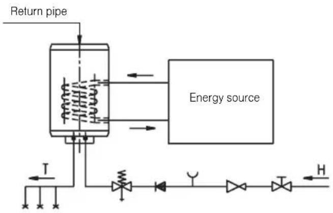
Combined GBK water heater operates in the same manner as the electrical GB water heater however, it has also been fitted with the cooling water heat exchanger allowing the sanitary water to be heated by alternative sources of energy (e.g. central heating, solar collector or heat pump). The two heating systems - electrical heating element and heat exchanger - can operate singly or concurrently. While the combined water heater is connected to the water supply system in the same manner as the GB model, the connection to the additional energy source has to be made as well. The inlet of the heating medium into the cooling water heat exchanger is colour-coded blue, while the outlet is colour-coded red. GBK water heaters can also be connected to the return hot water pipe. The return hot water pipe makes hot water instantly available at all points of use simultaneously. The return pipe can be connected to the inlet point at the top of the water heater after removing the plastic cap and unscrewing the stopper. The return pipe elements can also be purchased at any authorised dealer of our products at a later stage.
POWER CONNECTION
The power lead must be fitted to the water heater prior to connecting the heater to the power supply. In order to do this the plastic protective cover must be taken off by removing the plate inserted into the front side of the cover. The plate can be released by carefully inserting a flat screwdriver into the fissure between the plate and the protective cap, first next to the thermostat knob and then into the fissure opposite the knob. Once loose, the plate can subsequently be removed by hand. In order to remove the plastic protective cover, the thermostat knob must also be removed and both fixing screws undone. The protective cover can be re-fitted following the same procedure in reverse. The water heater must be connected to the power supply in accordance with the requirements set out in the relevant standards applying to the electrical installations. For safety reasons, a switch should be installed on the lead connecting the heater to the power grid, i.e. a switch disconnecting both power supply poles with the minimum of 3 mm distance between the open contacts.
Key:
1 - Thermostat
2 - Bimetal fuse
3 - Heating element (2 x 1000 W)
4 - Light indicator
5 - Connector
L - Phase conductor N - Neutral conductor ⊥ - Earth conductor
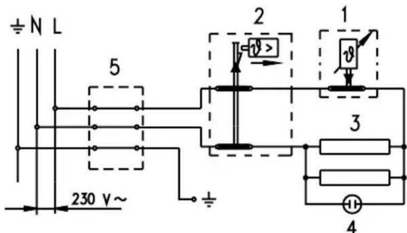
WARNING: The appliance must be disconnected from the power supply prior to doing anything that requires you to open the body of the water heater!
After the connection to water and electric network the heater is ready for use.
By turning the knob of thermostat at the front side of the protecting cover, the wished temperature of water between 25^ C and 75^ C is chosen. We recommend the adjustment of the knob to the position “E”. Such an adjustment is the most economic; with it the temperature of water shall be about 55^ C, the excretion of lime-stone and thermal loss shall be smaller as by adjustment to higher temperature.
The operation of electric immersion heaters is shown by pilot light. On the perimeter of the water heater there is a built-in thermometer which is showing the temperature of water. When the heater shall not be used during a longer time, its contents must be protected against freezing so that the power supply (electricity) shall not be switched off, but the thermostat knob shall be adjusted to the position “*”. With this adjustment the heater shall maintain the water temperature by about 10°C. But when the heater is switched-off from the electric network, at risk for freezing, the water must be emptied from it.
Before draining water heater should be disconnected from main supply. Than hot water valves on taps should be opened. Water heater is to be drained through inlet connection. For this purpose it is recommendable to put special fitting or a drain valve between inlet connection of water heater and safety valve. If this is not the case water can be drained directly through safety valve by putting the lever or screw cap of safety valve to "Test" position. After draining through inlet pipe there is small quantity of residual water which is to be drained by taking off of heating flange."
The outside of the water heater is cleaned by a mild solution of detergent, The solvents or rough cleaning means should not be used.
By regular service check of impeccable operation must be assured and a long lifetime of the water heater. The first check must be performed by an authorised service workshop after about two years after the first connection. At check, the use of anti-corrosion protecting anode is checked and if necessary lime stone must be cleaned which with regard to the quality, quantity and temperature of the water used is gathered in the inside of the water heater. Service workshop shall after check recommend also the date of next check of the water heater with regard to the established results.
Never try to repair any possible faults of the water heater by yourself, but inform about it the nearest authorised service workshop.
Štovani kupče! Zahvaljujemo Vam na povjerenju što ste nam ga iskazali kupnjom našeg proizvoda. MOLIMO VAS DA PRIJE MONTAŽE I PRVE UPORABE POMNO PROČITATE UPUTE ZA MONTAŽU, UPORABU I ODRŽAVANJE ELEKTRIČNE GRIJALICE VODE.
UREĐAJ NIJE NAMIJENJEN NA KORIŠTENJE ZA OSOBE (UKLJUČUJUĆI I DJECU), SA SMANJENIM FIZIČKIM, PSIHIČKIM ILI SENZORNIM SPOSOBNOSTIMA ILI NEDOSTATAK ISKUŠENJA OZ. SAZNANJA, OSIM AKO SE NADZIRE ILI SU OBRAZOVANI U POGLEDU KORIŠTENJA, OD OSOBE KOJA JE ODGOVORNA ZA NJIHOVU SIGURNOST.
DJECA TREBAJU BITI POD NADZOROM, KAKO BI SE OSIGURALO, DA SE ONI NE IGRAJU S UREĐAJEM.