
XLA 3200 - Loudspeaker BOSCH - Free user manual and instructions
Find the device manual for free XLA 3200 BOSCH in PDF.


| Product type | Passive column speaker |
| Brand | Bosch |
| Model | XLA 3200 (LBC 3200/00) |
| Dimensions (H x W x D) | 600 x 80 x 90 mm |
| Weight | 3 kg |
| Nominal power | 30 W (with settings 30-15-7.5 W) |
| Maximum power | 45 W |
| Effective frequency range | 190 Hz to 18 kHz (-10 dB) |
| Sound pressure level | 106 dB at 30 W / 91 dB at 1 W (1 kHz, 1 m) |
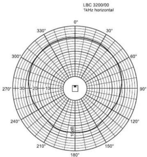
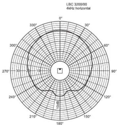
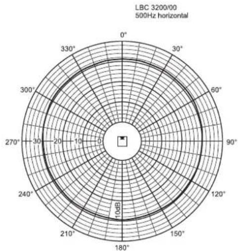
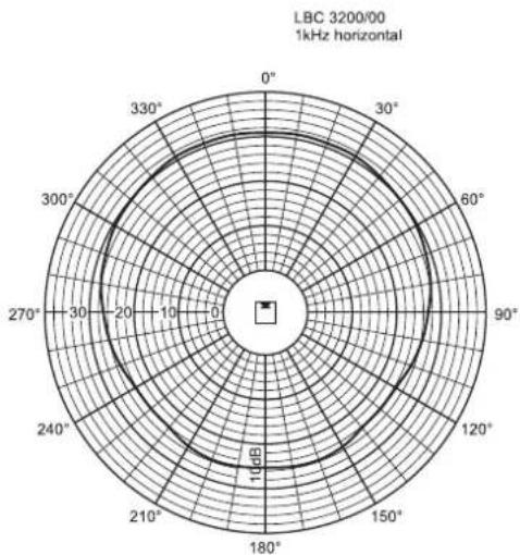
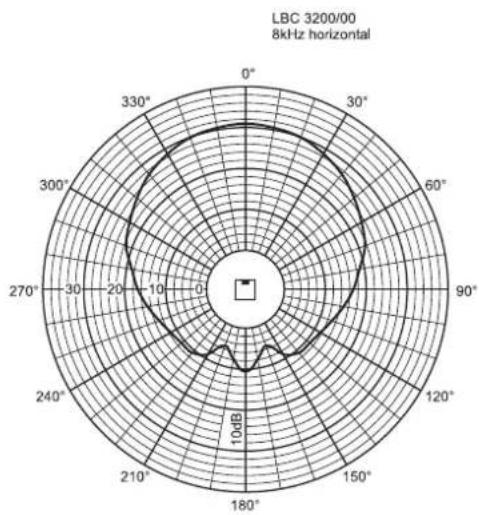
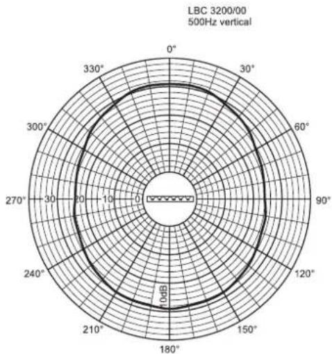
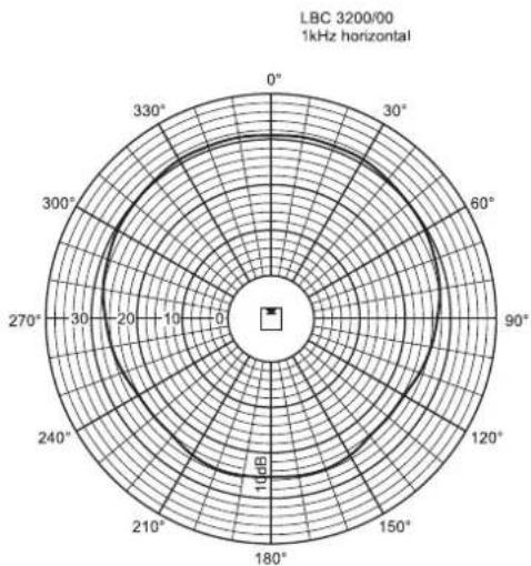
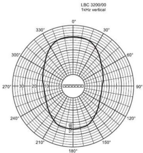
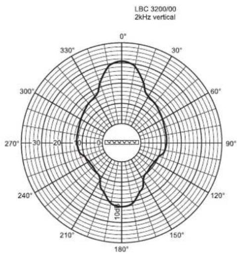
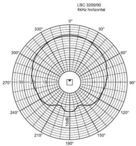
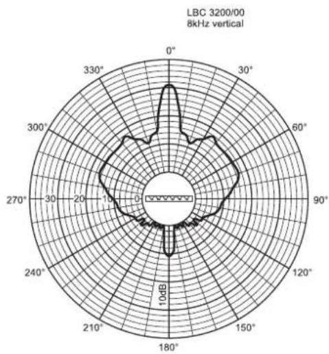
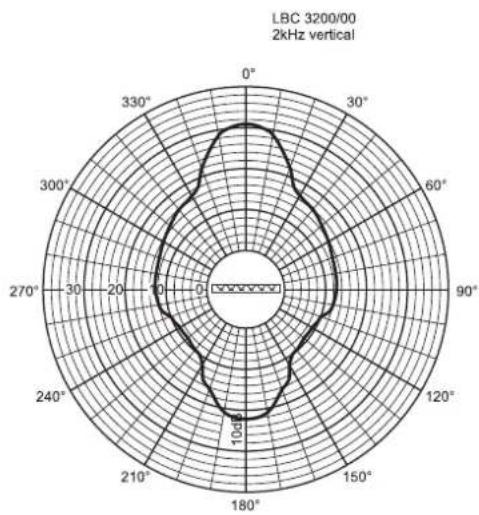
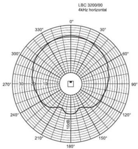
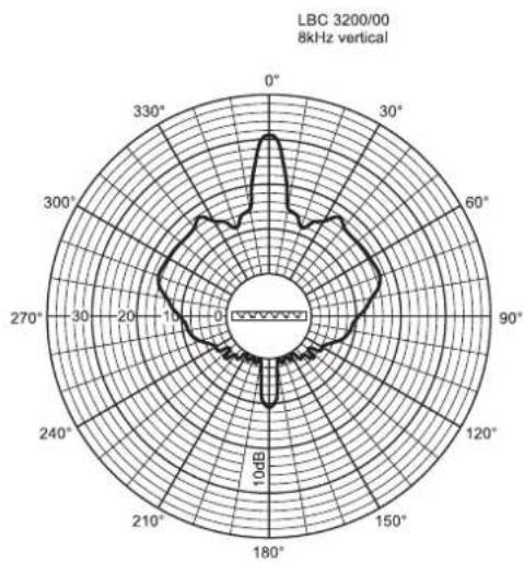
| Horizontal opening angle | 220° at 1 kHz / 130° at 4 kHz (-6 dB) |
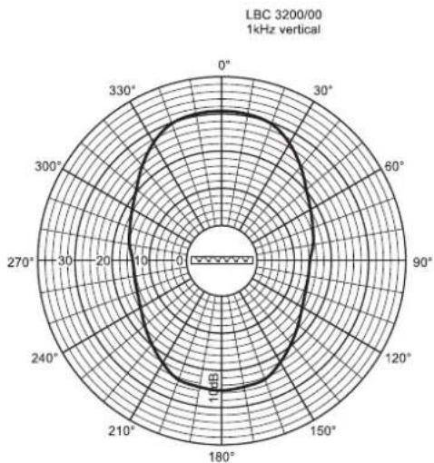
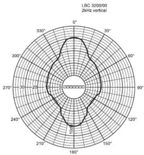
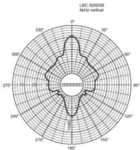
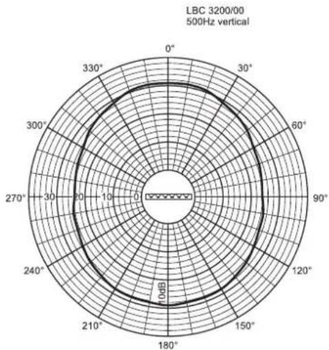
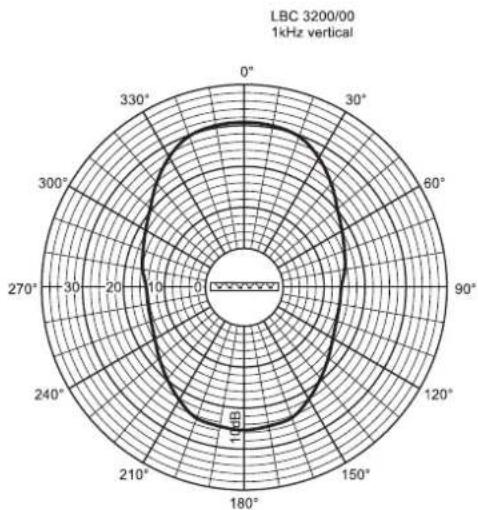
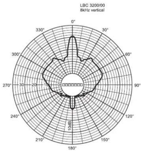
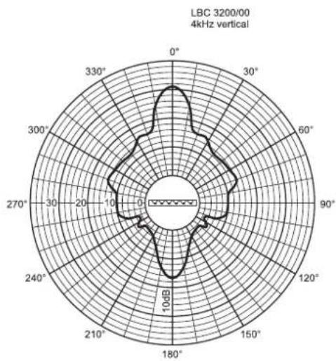
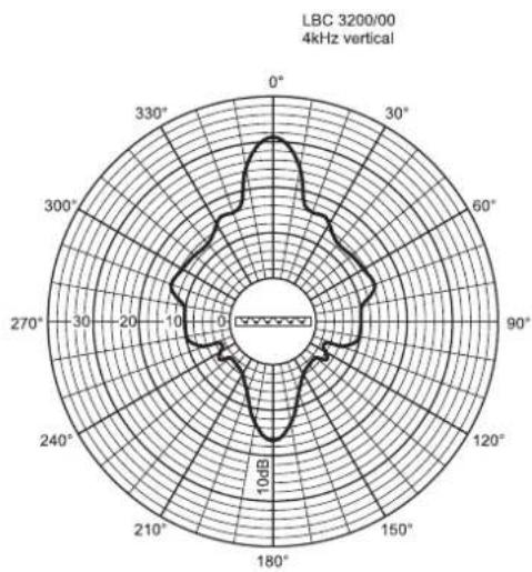
| Vertical opening angle | 70° at 1 kHz / 18° at 4 kHz (-6 dB) |
| Nominal input voltage | 100 V |
| Nominal impedance | 333 Ω |
| Connection | Screw terminal |
| Color | Silver |
| Ambient temperature | -25 °C to +55 °C |
| Safety | Complies with EN 60065 |
| Intended use | Indoor installation, restricted or medium spaces |
| Mounting | Wall, on tripod or additional bracket (optional accessories) |
| Maintenance | Clean the exterior with a soft, dry cloth. Do not use abrasive products. |
| Spare parts | Contact Bosch service for spare parts. |
| General information | Designed for constant directivity, ideal for speech sound reinforcement. |
Frequently Asked Questions - XLA 3200 BOSCH
User questions about XLA 3200 BOSCH
0 question about this device. Answer the ones you know or ask your own.
Ask a new question about this device
Download the instructions for your Loudspeaker in PDF format for free! Find your manual XLA 3200 - BOSCH and take your electronic device back in hand. On this page are published all the documents necessary for the use of your device. XLA 3200 by BOSCH.
USER MANUAL XLA 3200 BOSCH

Security Systems
Installation Manual EN Line Array Loudspeakers Manuel d'installation FR Enceintes colonnes Installationshandbuch DE Line-Array-Lautsprecher Manual de instalación ES Altavoces de línea vertical Installatiehandleiding NL Line Array Luidsprekers Manuale d'installazione IT Colonne sonore Manual de instalação PT Coluna linear de altifalantes
Installation Manual
EN Line Array Loudspeakers 5
Installationshandbuch
DE Line-Array-Lautsprecher 49
Contents Page
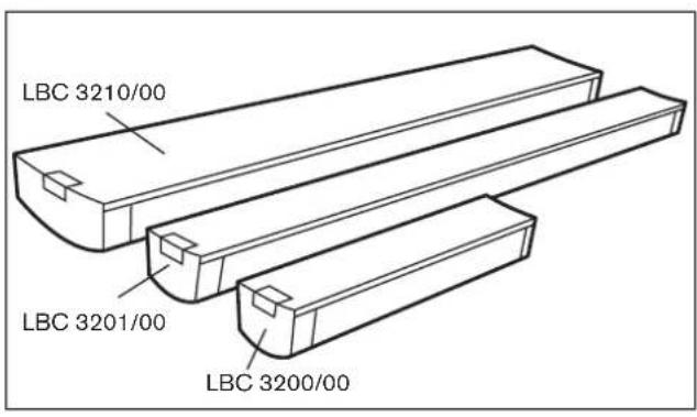
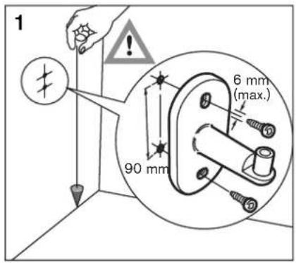
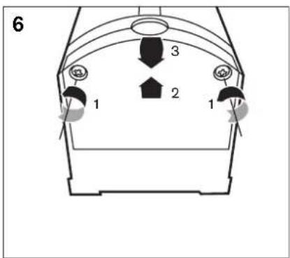
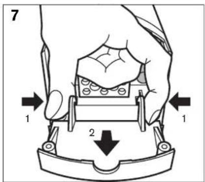
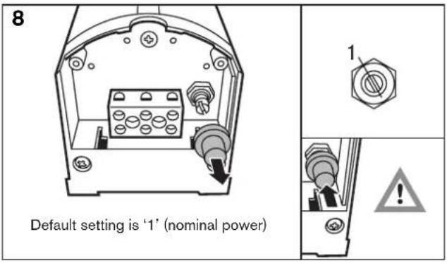
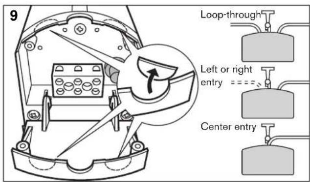
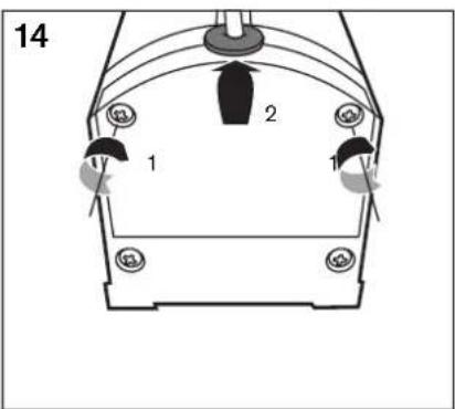
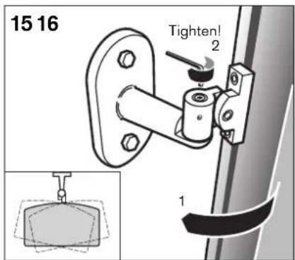
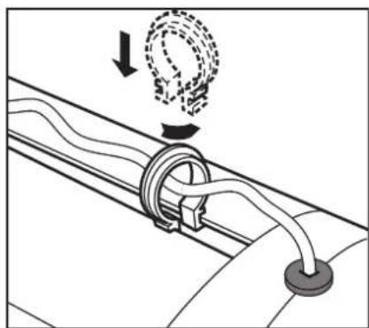
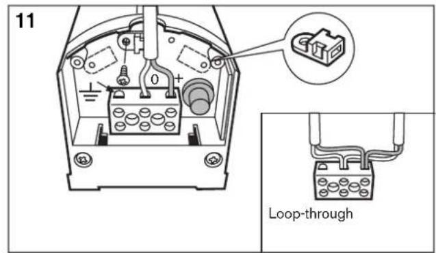
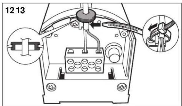
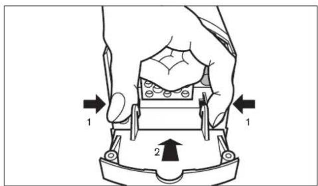
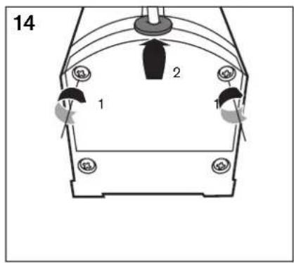
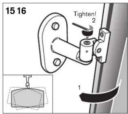
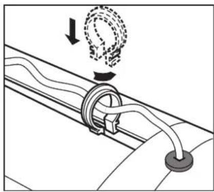
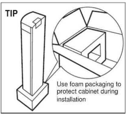
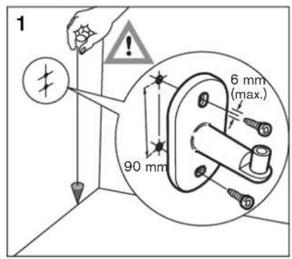
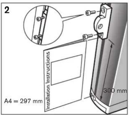
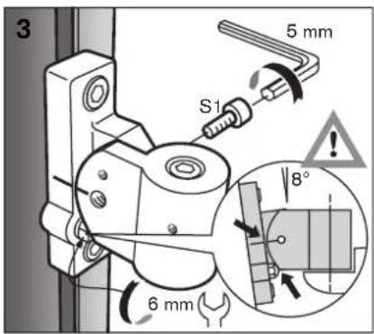
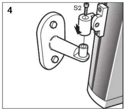
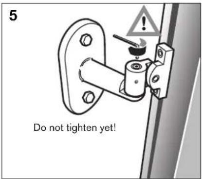
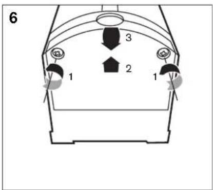
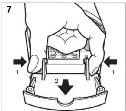
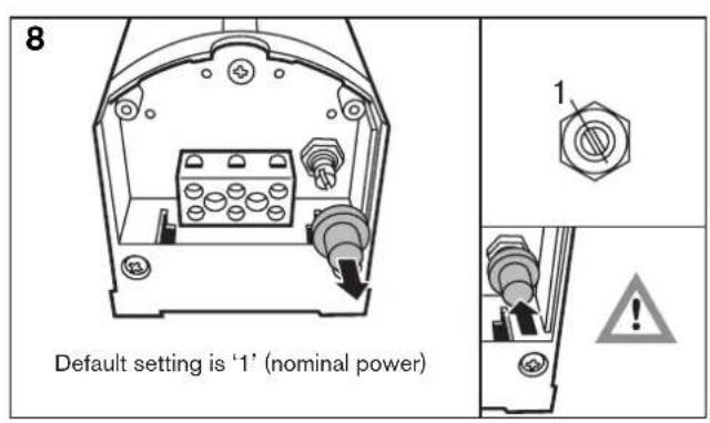
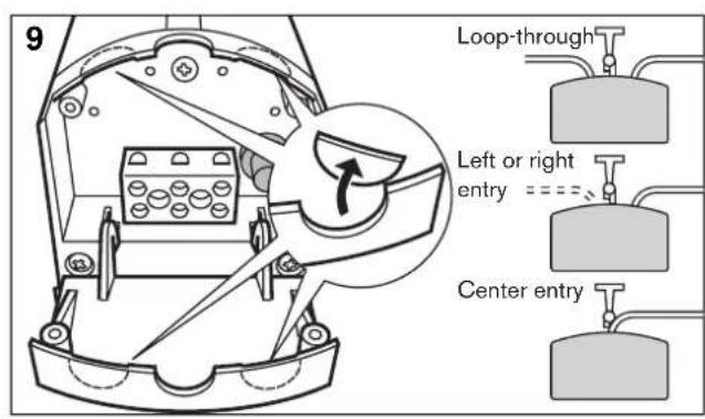
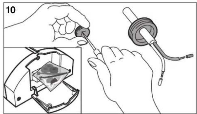
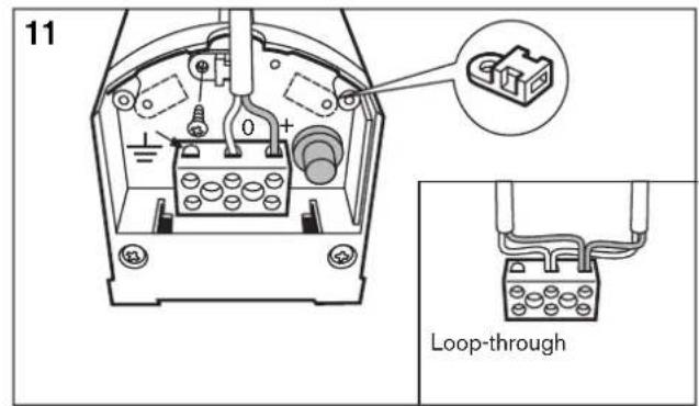
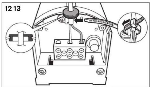
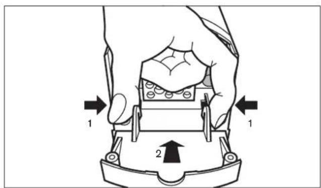
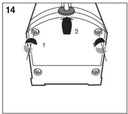
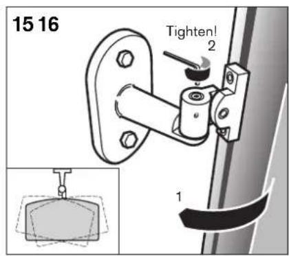
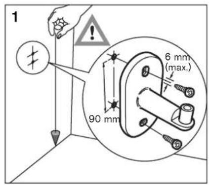
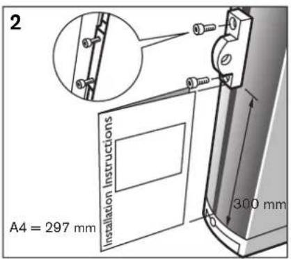
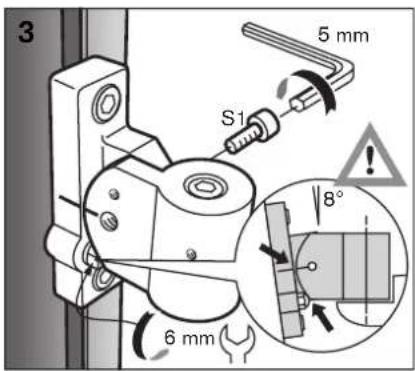
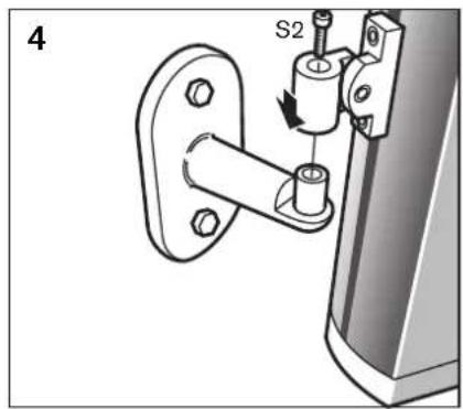
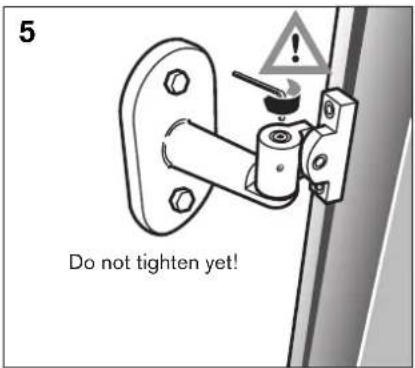
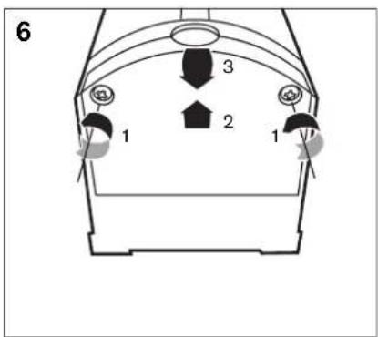
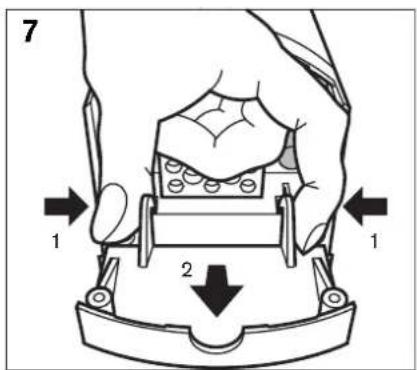
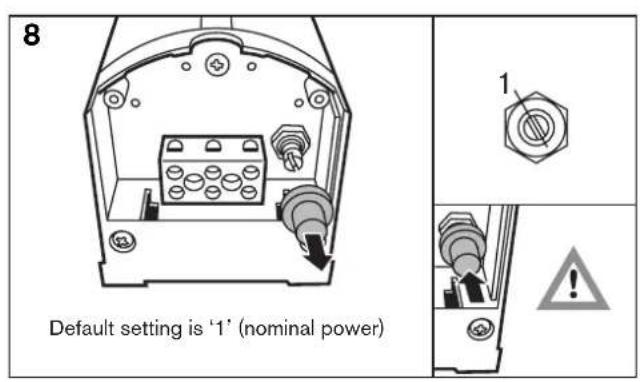
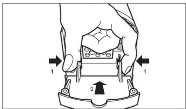
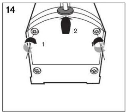
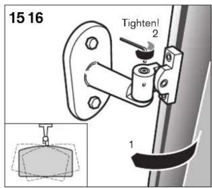
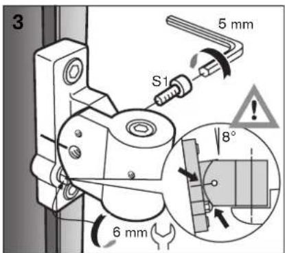
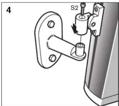
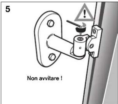
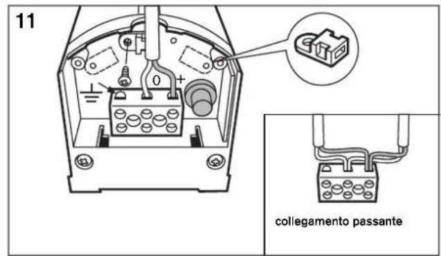
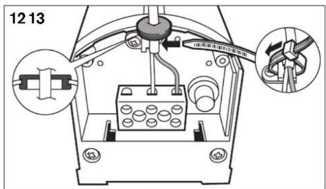
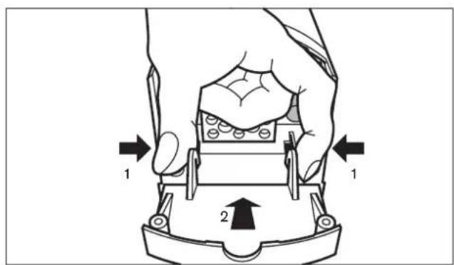
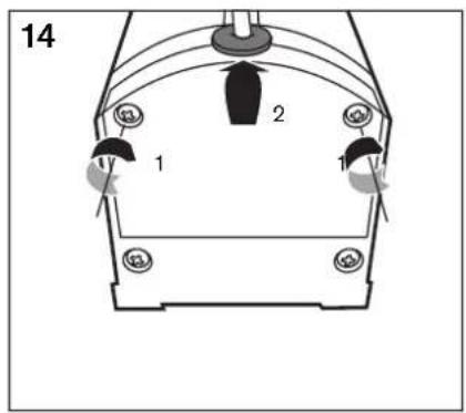
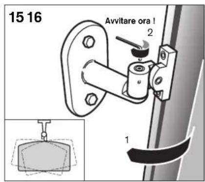
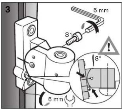
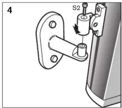
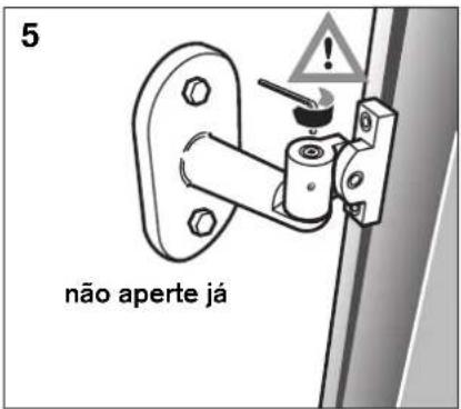
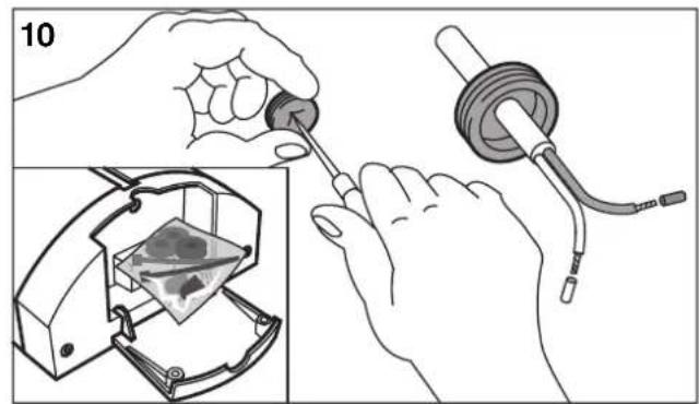
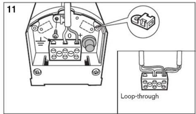
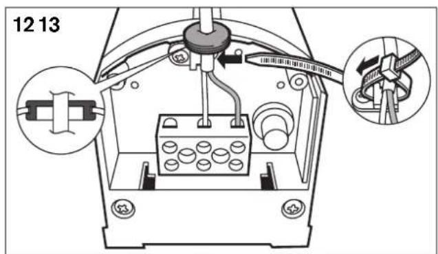
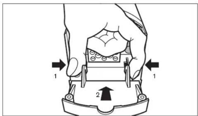
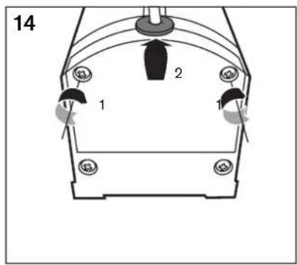
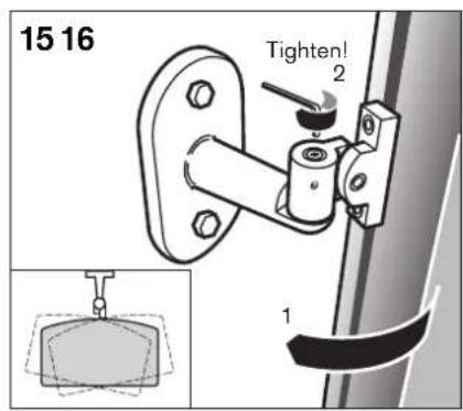
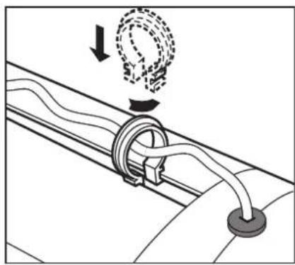
Installation guide (fig 1 - fig 17) ......6
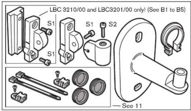
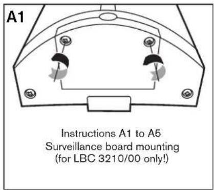
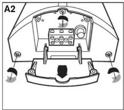
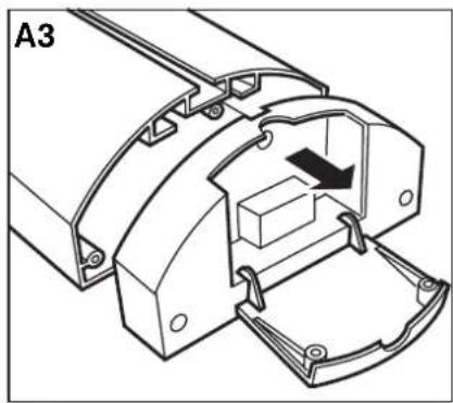
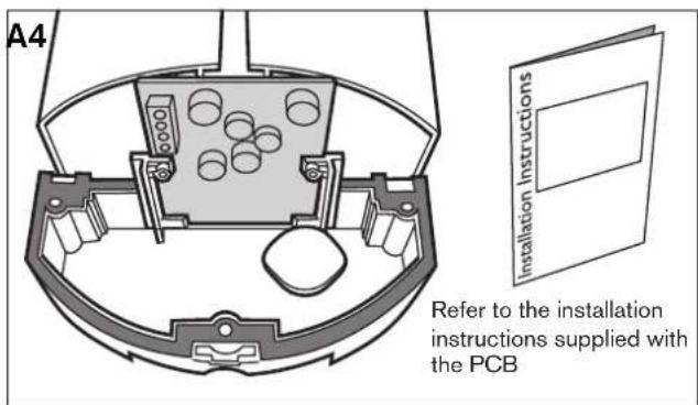
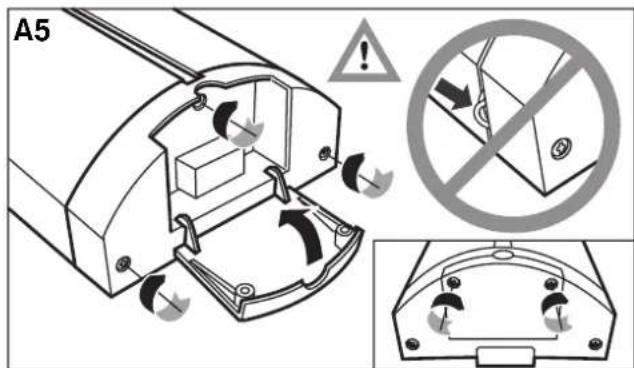
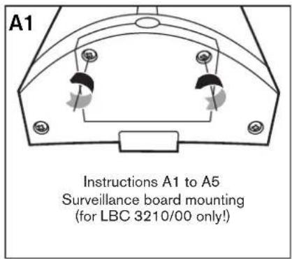
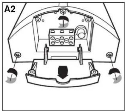
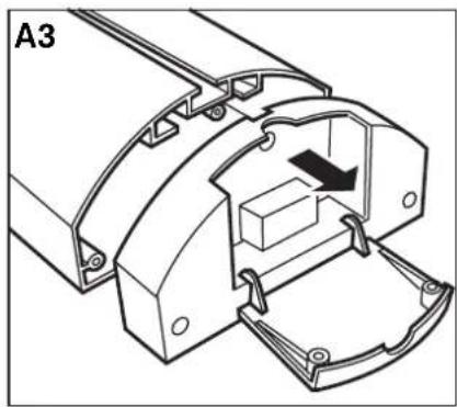
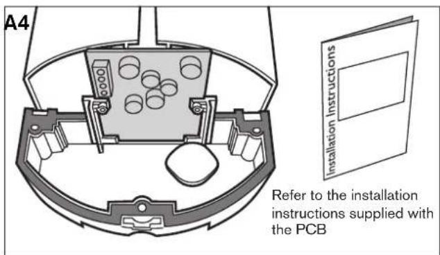
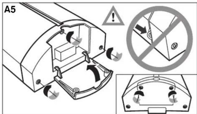
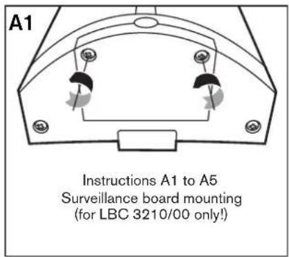
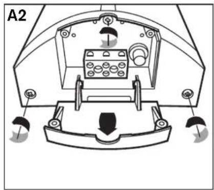
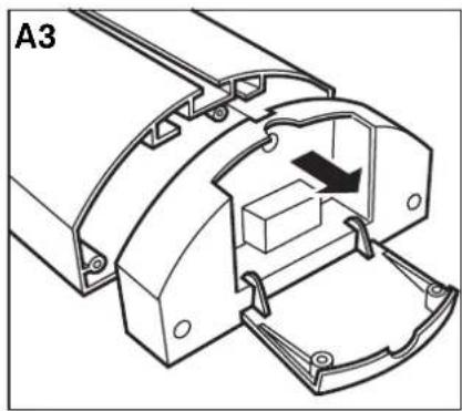
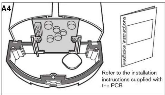
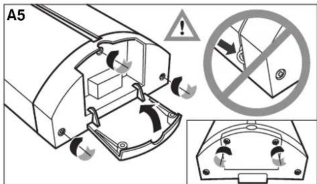
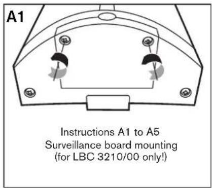
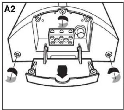
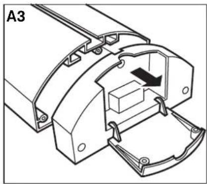
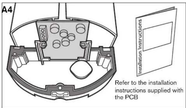
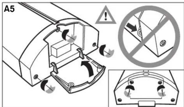
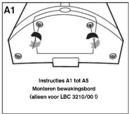
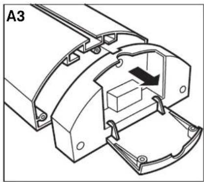
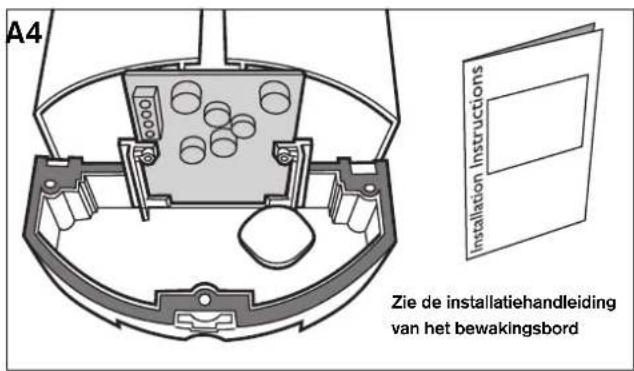
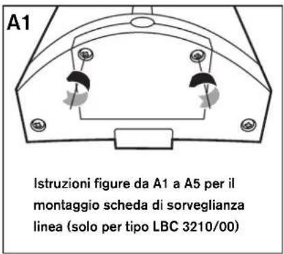
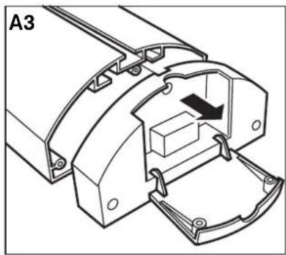
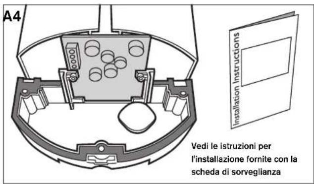
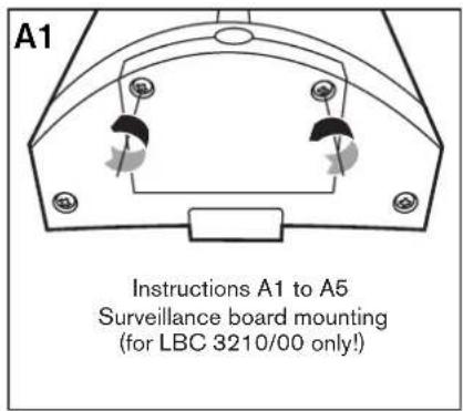
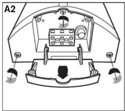
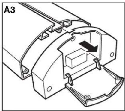
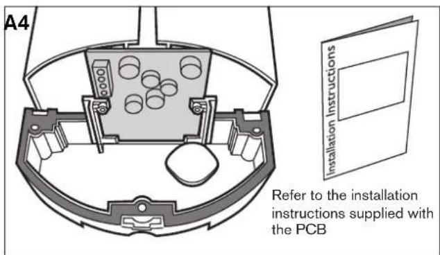
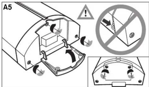
Line/Loudspeaker supervision board mounting (optional) (fig A1 - fig A5) ....8
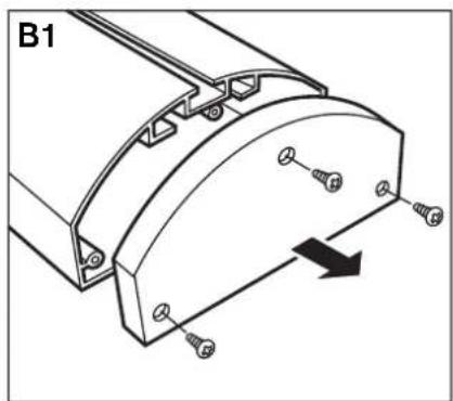
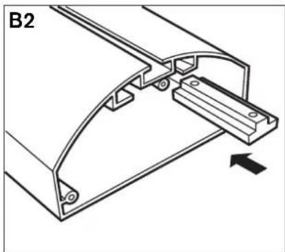
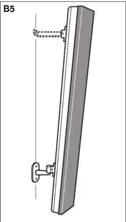
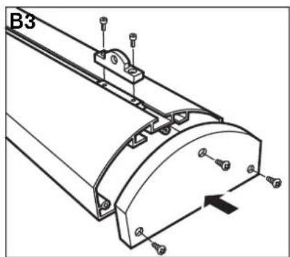
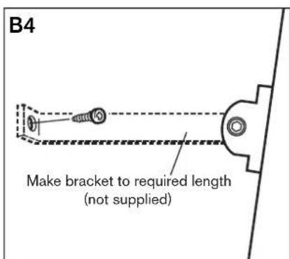
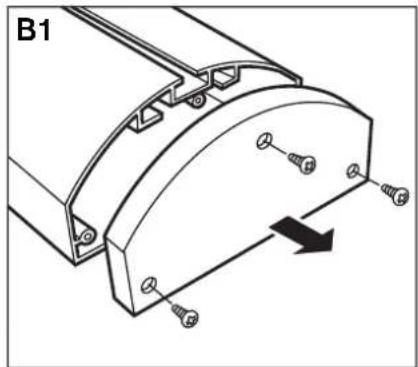
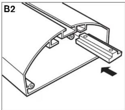
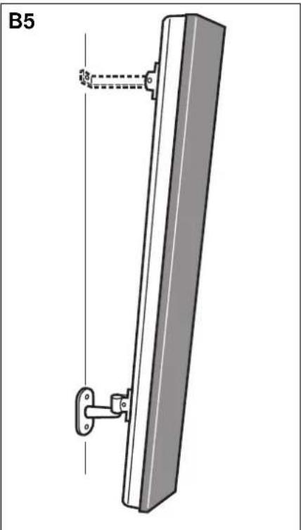
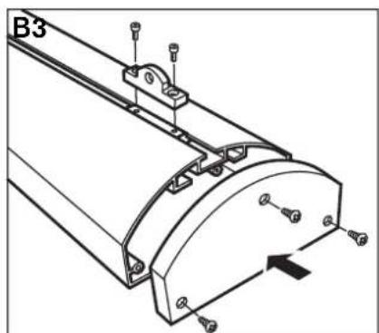
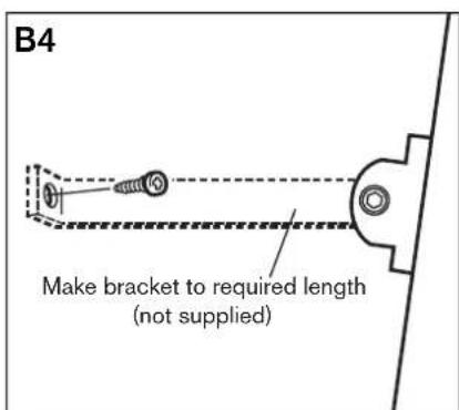
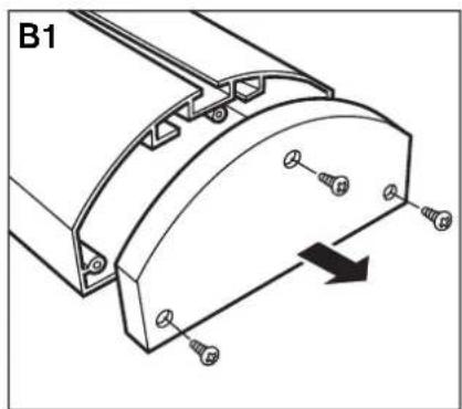
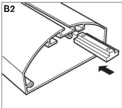
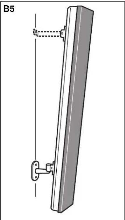
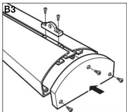
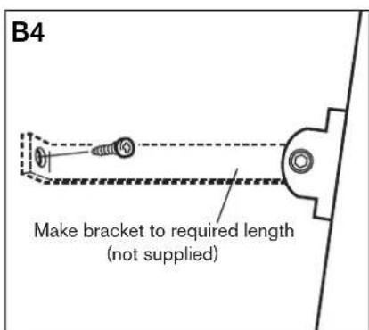
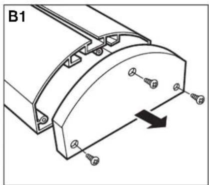
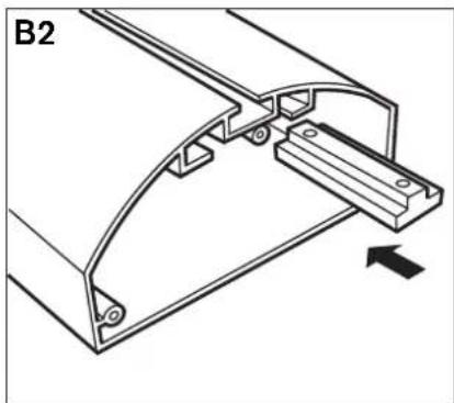
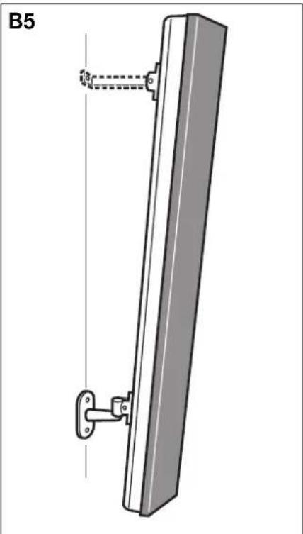
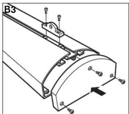
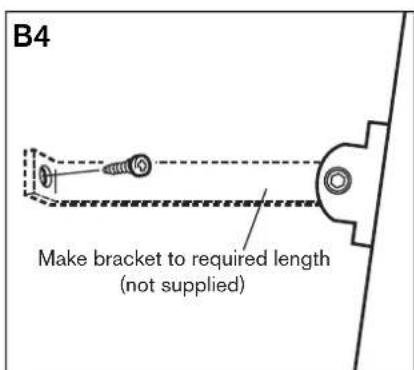
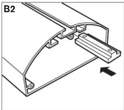
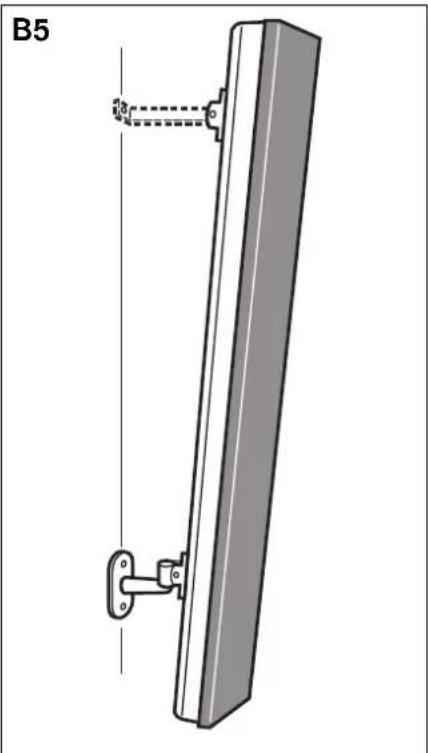
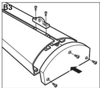
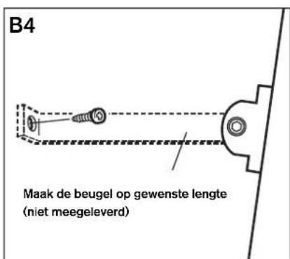
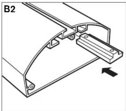
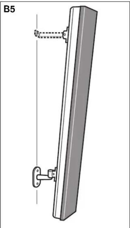
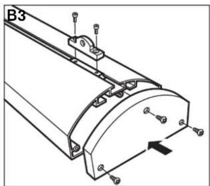
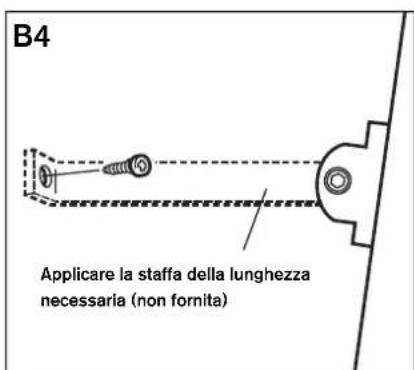
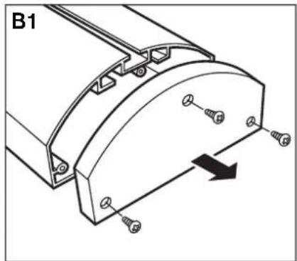
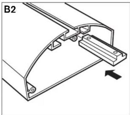
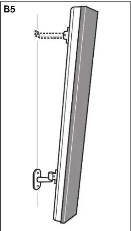
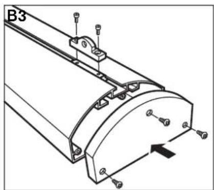
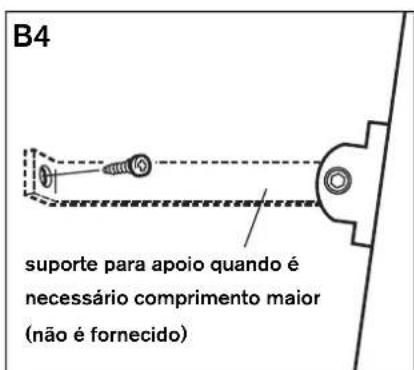
Additional bracket mounting (optional) (fig B1 - fig B5) 8
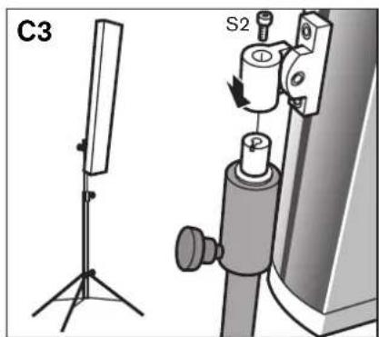
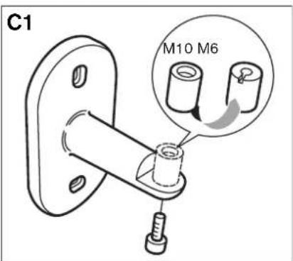
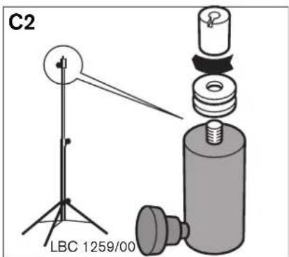
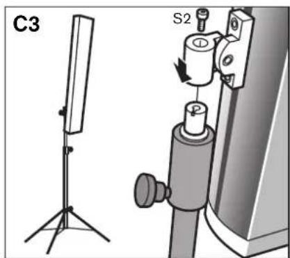
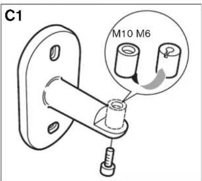
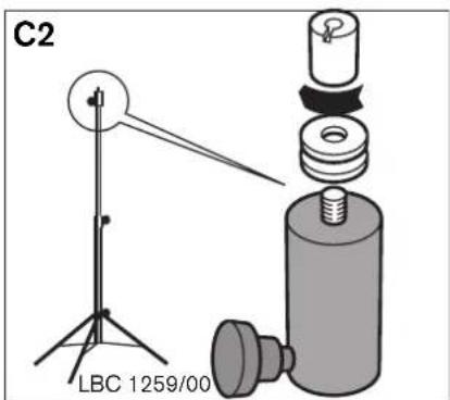
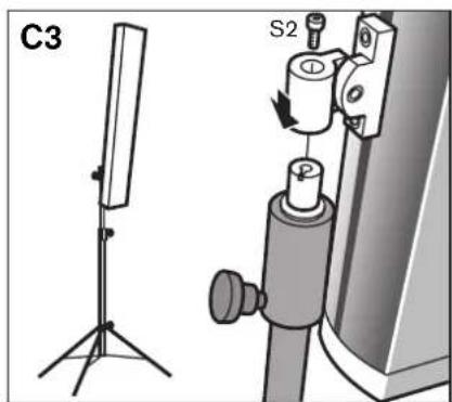
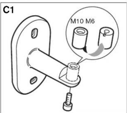
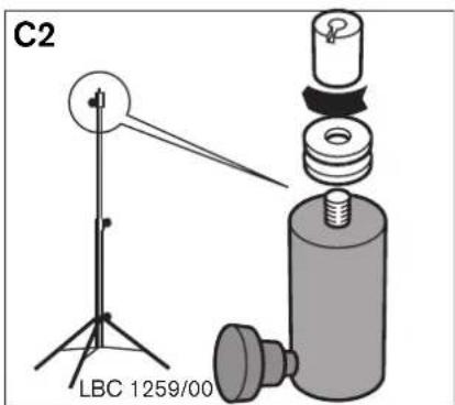
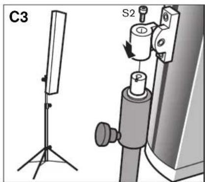
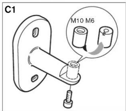
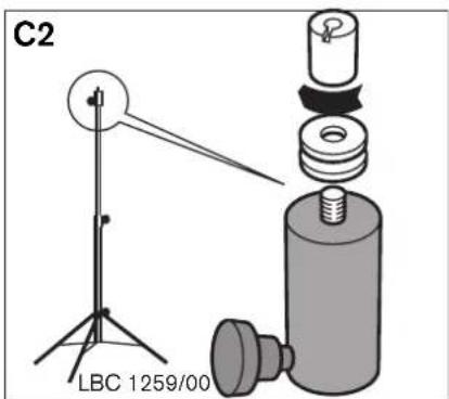
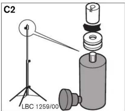
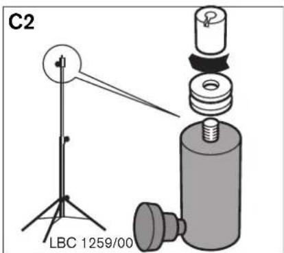
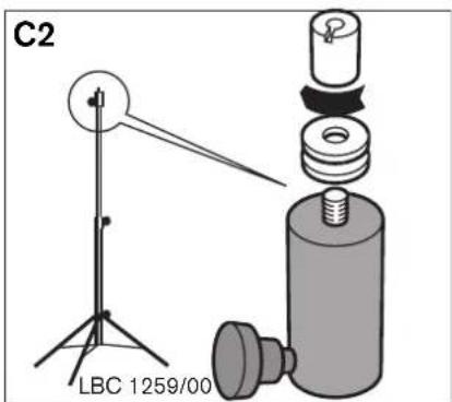
Foorstand mounting (optional) (fig C1 - fig C3)......8
Listening area and related mounting height LBC 3200/00 ....9
Listening area and related mounting height LBC 3201/00....11
Listening area and related mounting height LBC 3210/00....14
Technical data LBC 3200/00....17
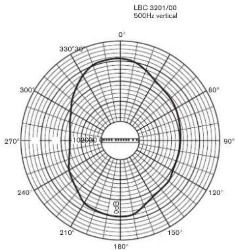
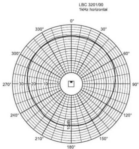
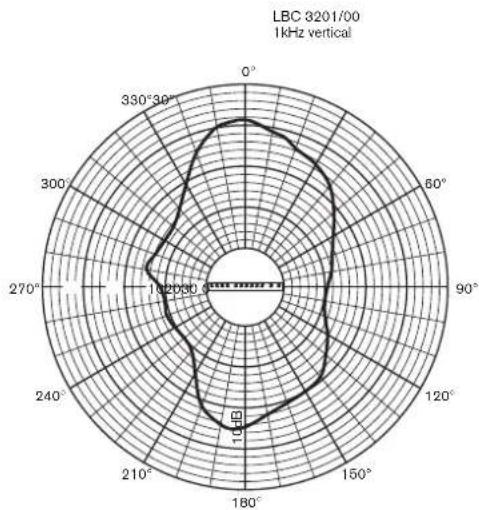
Technical data LBC 3201/00 ....20
Technical data LBC 3210/00 ......23
Listening area and related mounting height for XLA3200/00
Determining mounting height and angle for the LBC3200 loudspeaker array:
- Determine the dimensions of the desired 'listening area' (a horizontal plane at the level of the listeners' ears – refer to the dashed line in figure 1).
- Determine the angle at which the loudspeaker array is to be mounted. The array is designed to beam sound just above the listeners' heads, and it is recommended not to exceed an angle of 6°. There are two approaches, each with specific pros and cons.
- Approach 1: Maximized listening area When a large listening area is desired, an angle of about 3° is recommended (see figure 1). Note that when walking away from the loudspeaker array, the sound pressure level will decrease by an amount that depends on the room reverberation. To hear high tones clearly, the listener should be able to see the loudspeaker array.
- Approach 2: Minimized sound pressure level variation When less sound pressure level variation is desired, an angle of 5° is recommended. Note that this reduces the size of the total listening area compared to approach 1, and that the space very close to the loudspeaker array ('A' in figure 2) is not part of the listening area. Diagram 1 shows the relationship between 'A' and the mounting height of the loudspeaker array when using a 5° installation angle.
- After selecting the most appropriate approach (mounting angle), the mounting height of the loudspeaker is determined by focusing the 0°-axis of the loudspeaker array to the desired position just above ear level of the furthest listener. This can be adjusted by mounting the loudspeaker higher or lower on the wall.
Now you can mount the loudspeaker array for optimal acoustic performance.
Installation questions and answers:
- May I install the LBC3200 loudspeaker array the same as LBC3210 or LBC3201?
This loudspeaker array is designed for small and medium indoor environments. The optimal acoustical performance of this loudspeaker array is obtained by beaming the sound just above the listeners' heads. When this loudspeaker array is mounted as the LBC3210 or LBC3201, a very small listening area results. This is also the reason for not using an angle greater than 6 degrees.
- If I cannot see the loudspeaker array, does it mean that I cannot hear high tones?
You can compare high tones with light. When something is between you and the light source, you do not see the light source with its full power. We call this shadow. We have the same situation with high tones. When a lot of people are sitting between you and the loudspeaker, you are sitting in the sound shadow. We experience that as a reduction of high tones.
Background information:
- Because of the many installing angles it is difficult to give a defined shape of the radiated sound from the loudspeaker array. - By installing the loudspeaker array at a small angle, a (very) large listening area can be reached. Depending of the amount of reverberation in the room and the sound shadow (people or objects in front of a listener who are blocking the direct sound source) the speech intelligibility on a far position may be low. In these situations, it is better to use more loudspeaker arrays to split the listening area.
- When you move further than the maximum position of the listening area (more than the maximum distance from the loudspeaker array), only the sound pressure level will decrease. There is almost no tone height variation. The decreasing of sound pressure level depends strongly on the reverberation of the room.
- When you are too close to the loudspeaker array (less than the minimum distance from the loudspeaker array) and are using the 5-degree approach a decline of the high tones will very soon occur.
- Because the loudspeakers are designed to beam the sound just above the listeners' heads, it is better not to mount the loudspeakers too high above the listening area.
- To determine exactly were the edges of the listening area are in your situation, you have to carry out a practical test at the location were the loudspeaker array is installed. This is a job for an experienced listener with well-trained ears. To do so, put pink noise through the loudspeaker array. It is better to reduce the lower tones for this test, as they do not contribute to speech intelligibility. Walk around in the listening area and listen to the high tones. The places were the high tones decreases rapidly are the edges of the listening area.
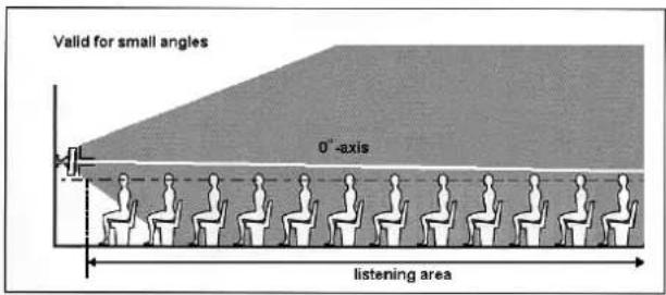
Figure 1 side view of loudspeaker array radiation mounted to the wall with a small angle
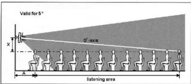
Figure 2: side view of loudspeaker array radiation mounted to the wall with a 5-degree angle
![| Distance A between the array and listening plane [m] | Height X between listening plane and array [cm] | | ---------------------------------------------------- | ---------------------------------------------- | | 0.0 | 0.0 | | 0.5 | 20.0 | | 1.0 | 40.0 | | 1.5 | 60.0 | | 2.0 | 80.0 | | 2.5 | 100.0…](/content/2026/05/811019/images/370a69426ff7266f4778db8188eef98399ab60b22faf3616866322958224d9ac.jpg)
Diagram 1: relation between listening area distance and loudspeaker array
Listening area and related mounting height for XLA3201/00
How to use these mounting method:
- Determine the dimensions of the desired 'listening area' (a horizontal plane at the level of the listeners' ears – refer to the dashed line in figure 1).
- Measure the maximum distance from loudspeaker array to the last listener in the listening area (corresponding to 'B' in figures 1, 2 and 3).
- Refer to diagram 1, and trace upwards from the maximum distance on the horizontal axis. From the vertical intersection with diagonal B-line, you go horizontal to the vertical axis. The X-value (height of loudspeaker array mounting bracket above the listening plane, 'X' in figure 1) is standing on this axis. The horizontal intersections with other diagonal lines provide information about the dimensions of the listening area. These numbers are related to figures 2 and 3 (see also example below).
- Figure 2 shows the 1kHz octave shape radiated by the loudspeaker array and figure 3 shows the 4kHz octave shape radiation. The listening area with the optimal acoustic performance is in these shapes. Ensure the 4kHz shape with the dimensions obtained using diagram 1 adequately covers the desired listening area.
- If the desired listening area is covered by the 4kHz shape, the X-value on the vertical axis show at what height the loudspeaker array must be mounted above the listening plane. Note that the loudspeaker array must be mounted at an angle of 8° at the chosen height!
Now you can mount the loudspeaker array for optimal acoustic performance.
Example:
The maximum distance from loudspeaker array to last listener is 15m. Tracing upwards from the 15m point on the horizontal axis of diagram 1 to the diagonal B-line and then sidewards to the vertical axis, the intersections with the other diagonal lines provide dimensions of the listening planes. In this example:
F-line (listening plane side length of 4kHz) = 11.1m
C-line (listening plane length) = 11m
E-line (half width listening plane of 4kHz) = 9.3m
A-line (minimum distance to listening plane) = 3.9m
On the vertical axis, the X-value (the height between the listening plane and loudspeaker array mounting bracket) is 1.8m.
Installation questions and answers:
- The desired listening area is too large and does not fit in the 4kHz shape. Try another loudspeaker array mounting height or use more loudspeaker arrays to get a larger listening area.
- Why use an angle of 8° for the loudspeaker array?
The radiated shapes shown in figures 2 and 3 with the dimensions in diagram 1 are only valid when the loudspeaker array is mounted at an angle of 8°. Only this situation provides constant sound pressure level and frequency response (constant directivity) in the listening area.
- Can I use the loudspeaker array with another angle?
You can use the loudspeaker arrays also with another angle but you will not get the optimum acoustic performance. For example, greater sound pressure level variation will be audible in the listening area. The values in diagram 1 are not valid for other angles. It is recommended never to use an angle greater than 8°.
- The loudspeaker array cannot be mounted as high as desired.
If the height cannot be reached due to ceiling limitations, for example, use an angle of less than 8°. Focus the 0°-axis of the loudspeaker array to the desired maximum position (see figure 4). Note that the table in diagram 1 and shapes in figures 2 and 3 are not valid for this situation. Check in the listening area if the speech intelligibility is acceptable.
Background information:
- The shapes are defined in an anechoic environment. In these shapes at anechoic conditions, you have a maximum of 6 dB sound pressure variation and much less perceived frequency response variation. In areas with normal or high reverberations, less sound pressure level variation takes place and the size of shapes will be bigger. The perceived frequency response in this shape will then be almost constant.
- When you go further than the maximum position of the listening area (beyond the maximum distance from the loudspeaker array) only the sound pressure level will decrease. There is almost no tone height variation. The decrease in sound pressure level depends strongly on the reverberation of the room.
- When you move too close to the loudspeaker arrays (less than the minimum distance from the loudspeaker array) a lack of high tones will very soon occur.
- Depending on the amount of reverberation in the room and the sound shadow (people or objects in front of a listener who block the direct sound source), the speech intelligibility at the furthest positions may be low. In these situations, it is better to use more loudspeaker arrays to split the listening area.
- The side lines of the shapes of figure 2 and 3 are the -6 dB points related to the sound pressure level on the 0°-axis.
• To get the best speech intelligibility, define a listening area where the 4 kHz octave shape covers the whole area.
• To determine exactly where the edges of the listening area are in your situation, you have to carry out a practical test at the location where the loudspeaker array is installed. This is a job for an experienced listener with well-trained ears. To do so, put pink noise through the loudspeaker array. It is better to reduce the lower tones for this test, as they do not contribute to speech intelligibility. Walk around in the listening area and listen to the high tones. The places where the high tones decrease rapidly are the edges of the listening area.
![| Size / shape of the listening plane [m] | Height between listening plane and array [m] | | --------------------------------------- | ------------------------------------------- | | 2 | 0.7 | | 5 | 1.8 | | 10 | 1.8 | | 15 | 3.7 | | 20 | 3.7 | | 25 | 3.7 | | 30 | 3.7 |](/content/2026/05/811019/images/23b75803f14d08704f508aa12dcc4e8f08f668fa8ec093bedfaeb3ccb034c9e6.jpg)
Diagram 1: relation between listening area and loudspeaker array mounting height
Diagonal line meanings
B-line: maximum distance from loudspeaker array to last listener.
D-line: half-width listening plane at 1kHz
F-line: listening plane side length at 4kHz
C-line: listening plane length
E-line: half-width listening plane at 4kHz
A-line: minimum distance to listening plane
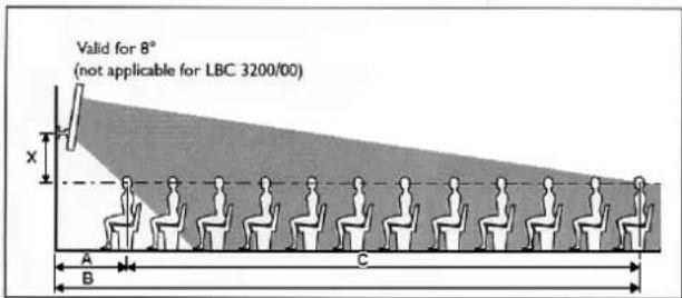
Figure 1: side view of loudspeaker array radiation and listening plane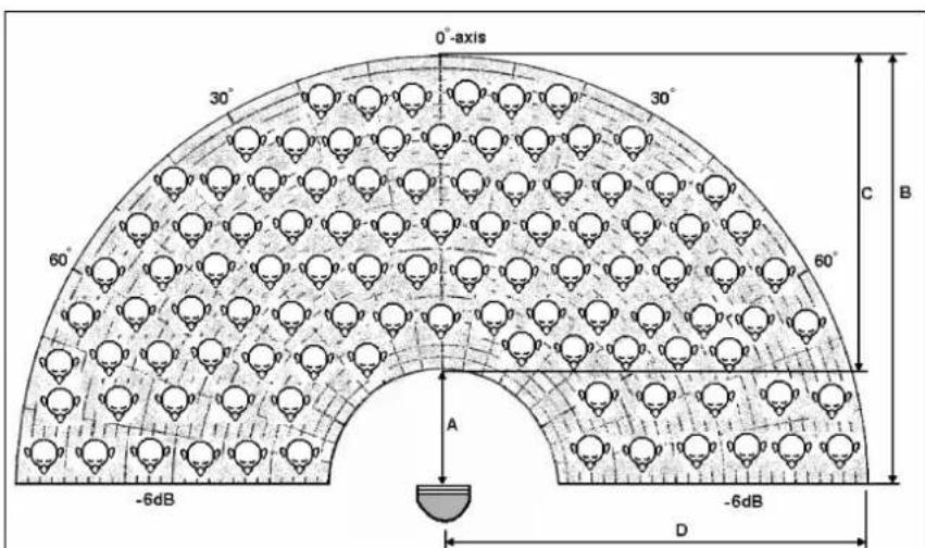
Figure 2: 1kHz octave shape of the loudspeaker array
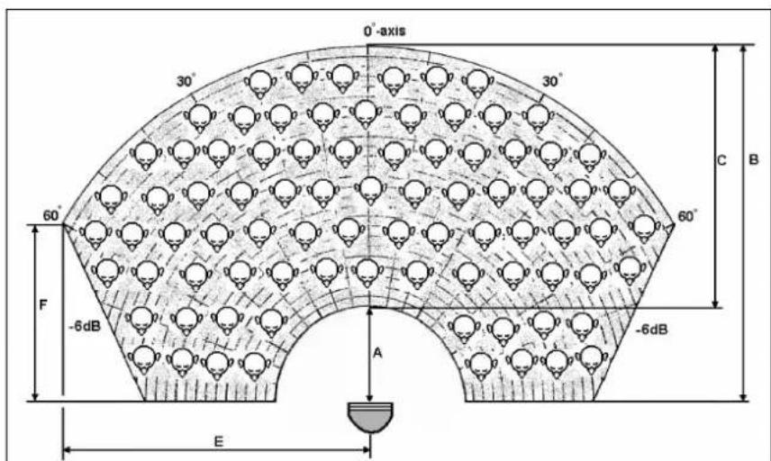
Figure 3: 4kHz octave shape of the loudspeaker array
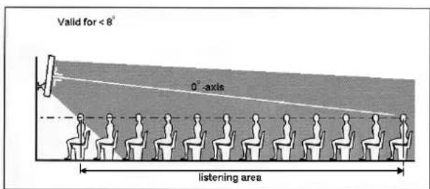
Figure 4: Focus the 0°-axis of the loudspeaker array to the maximum position
Listening area and related mounting height for XLA3210/00
How to use these mounting methods:
- Determine the dimensions of the desired 'listening area' (a horizontal plane at the level of the listeners' ears – refer to the dashed line in figure 1).
- Measure the maximum distance from loudspeaker array to the last listener in the listening area (corresponding to 'B' in figures 1, 2 and 3).
- Refer to diagram 1, and trace upwards from the maximum distance on the horizontal axis. From the vertical intersection with diagonal B-line, you go horizontal to the vertical axis. The X-value (height of loudspeaker array mounting bracket above the listening plane, 'X' in figure 1) is standing on this axis. The horizontal intersections with other diagonal lines provide information about the dimensions of the listening area. These numbers are related to figures 2 and 3 (see also example below).
- Figure 2 shows the 1kHz octave shape radiated by the loudspeaker array and figure 3 shows the 4kHz octave shape radiation. The listening area with the optimal acoustic performance is in these shapes. Ensure the 4kHz shape with the dimensions obtained using diagram 1 adequately covers the desired listening area.
- If the desired listening area is covered by the 4kHz shape, the X-value on the vertical axis show at what height the loudspeaker array must be mounted above the listening plane. Note that the loudspeaker array must be mounted at an angle of 8° at the chosen height!
Now you can mount the loudspeaker array for optimal acoustic performance.
Diagram example:
The maximum distance from loudspeaker array to last listener is 15m. Tracing upwards from the 15m point on the horizontal axis of diagram 1 to the diagonal B-line and then sidewards to the vertical axis, the intersections with the other diagonal lines provide dimensions of the listening planes. In this example:
F-line (listening plane side length of 4kHz) = 12.2m
C-line (listening plane length) = 11m
E-line (half width listening plane of 4kHz) = 8.6m
A-line (minimum distance to listening plane) = 3.9m
On the vertical axis, the X-value (the height between the listening plane and loudspeaker array mounting bracket) is 1.8m.
Installation questions and answers:
- The desired listening area is too large and does not fit in the 4kHz shape.
Try another loudspeaker array mounting height or use more loudspeaker arrays to get a larger listening area.
- Why use an angle of 8° for the loudspeaker array?
The radiated shapes shown in figures 2 and 3 with the dimensions in diagram 1 are only valid when the loudspeaker array is mounted at an angle of 8°. Only this situation provides constant sound pressure level and frequency response (constant directivity) in the listening area.
- Can I use the loudspeaker array with another angle?
You can use the loudspeaker arrays also with another angle but you will not get the optimum acoustic performance. For example, greater sound pressure level variation will be audible in the listening area. The values in diagram 1 are not valid for other angles. It is recommended never to use an angle greater than 8°.
- The loudspeaker array cannot be mounted as high as desired.
If the height cannot be reached due to ceiling limitations, for example, use an angle of less than 8°. Focus the 0°-axis of the loudspeaker array to the desired maximum position (see figure 4). Note that the table in diagram 1 and shapes in figures 2 and 3 are not valid for this situation. Check in the listening area if the speech intelligibility is acceptable, as messages must be audible.
Background information:
- The shapes are defined in an anechoic environment. In these shapes at anechoic conditions, you have a maximum of 6dB sound pressure variation and much less perceived frequency response variation. In areas with normal or high reverberations, less sound pressure level variation takes place and the size of shapes will be bigger. The perceived frequency response in this shape will then be almost constant.
- When you go further than the maximum position of the listening area (beyond the maximum distance from the loudspeaker array) only the sound pressure level will decrease. There is almost no tone height variation. The decrease in sound pressure level depends strongly on the reverberation of the room.
- When you move too close to the loudspeaker arrays (less than the minimum distance from the loudspeaker array) a lack of high tones will very soon occur.
• Depending on the amount of reverberation in the room and the sound shadow (people or objects in
• Depending on the amount of reverberation in the room and the sound shadow (people or objects in front of a listener who block the direct sound source), the speech intelligibility at the furthest positions may be low. In these situations, it is better to use more loudspeaker arrays to split the listening area.
- The side lines of the shapes of figure 2 and 3 are the -6dB points related to the sound pressure level on the 0°-axis.
- To get the best speech intelligibility, define a listening area where the 4kHz octave shape covers the whole area.
To determine exactly where the edges of the listening area are in your situation, you have to carry out a practical test at the location where the loudspeaker array is installed. This is a job for an experienced listener with well-trained ears. To do so, put pink noise through the loudspeaker array. It is better to reduce the lower tones for this test, as they do not contribute to speech intelligibility. Walk around in the listening area and listen to the high tones. The places where the high tones decrease rapidly are the edges of the listening area.
![| Label | Height between listening plane and array [m] | |-------|---------------------------------------------| | A | 0.7 | | E | 3.8 | | C | 3.7 | | F | 3.6 | | B,D | 3.5 |](/content/2026/05/811019/images/f9c74e7aadf178b21389397ae94e7d5c5591b6f581da648ec2c49795efdde13f.jpg)
Diagram 1: relation between listening area and loudspeaker array mounting height
Line meaning
B-line: maximum distance from loudspeaker array to last listener. D-line: half-width listening plane at 1kHz F-line: listening plane side length at 4kHz C-line: listening plane length E-line: half-width listening plane at 4kHz A-line: minimum distance to listening plane
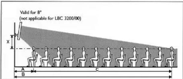
Figure 1: side view of loudspeaker array radiation and listening plane
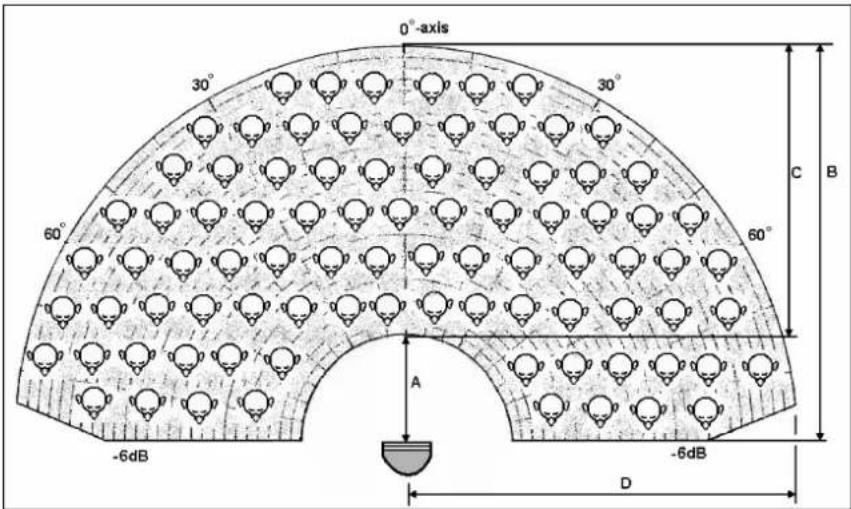
Figure 2: 1kHz octave shape of the loudspeaker array
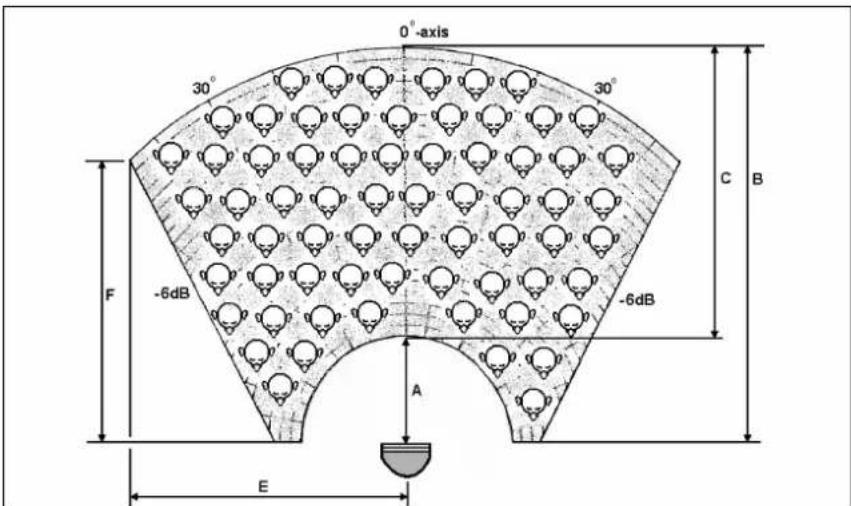
Figure 3: 4kHz octave shape of the loudspeaker array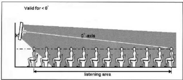
Figure 4: Focus the 0°-axis of the loudspeaker array to the maximum position
TECHNICAL PERFORMANCE DATA
| LBC 3200/00 | |
| Maximum power | 45 W |
| Rated power | 30 W (30-15-7.5 W) |
| Sound pressure level at | |
| 30 W/1 W (at 1 kHz, 1 m) | 106 dB/91 dB (SPL) |
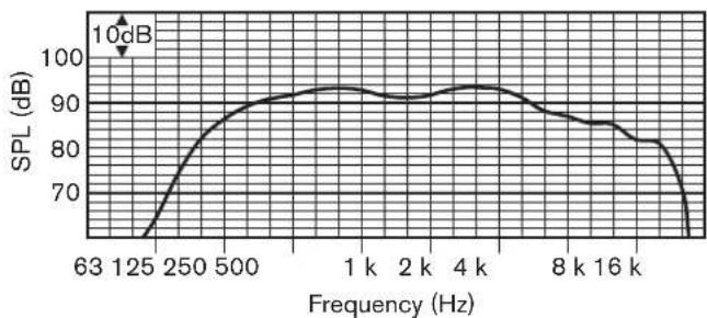
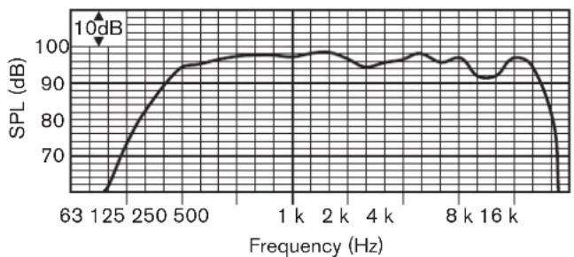
| Effective frequency range (-10 dB) | 190 Hz to 18 kHz |
| Opening angle | |
| (at 1 kHz/4 kHz, -6 dB) | |
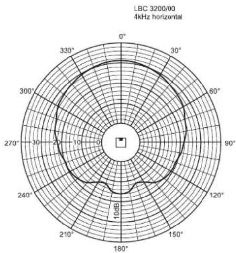
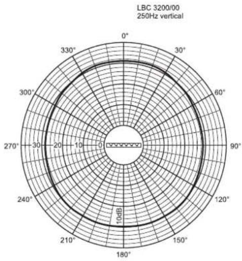
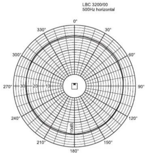
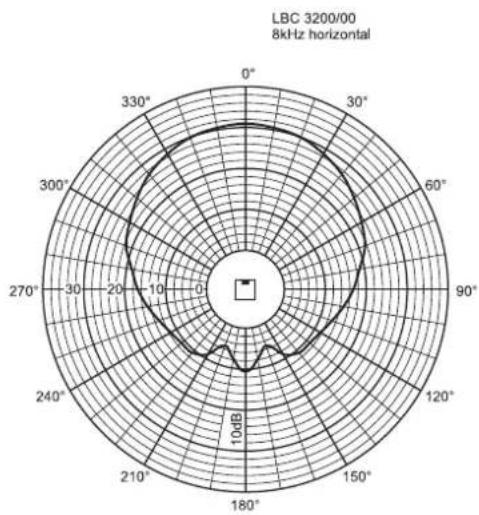
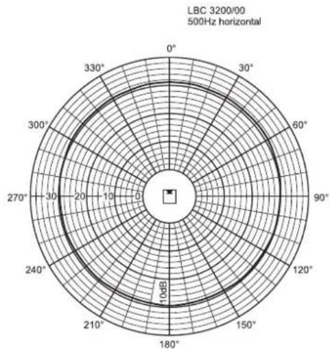
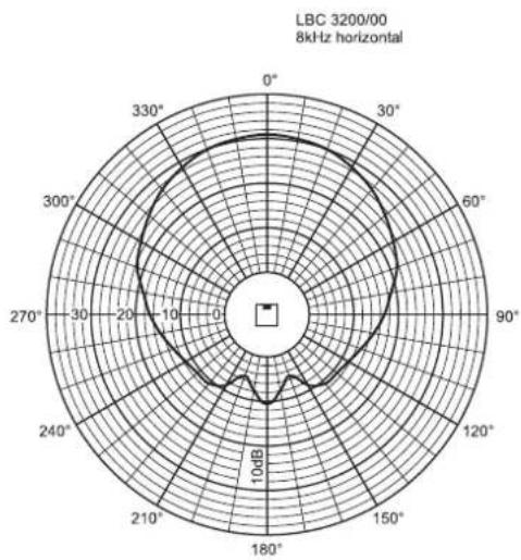
| Horizontal | 220° /130° |
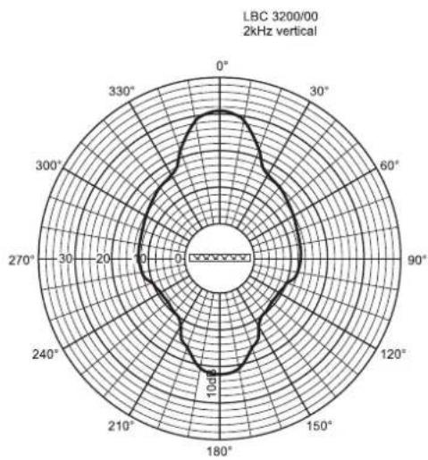
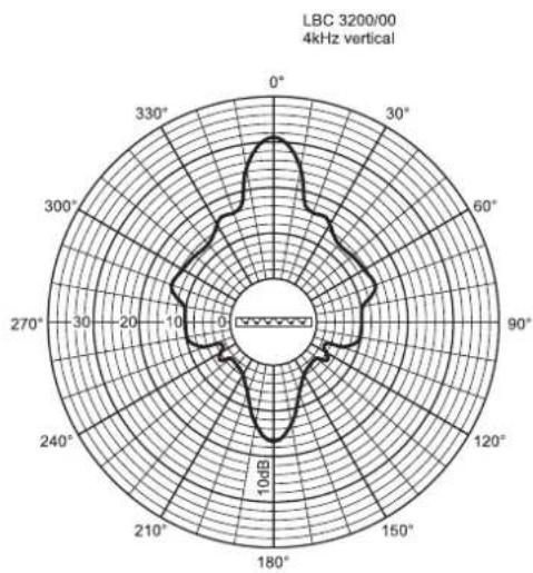
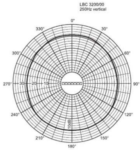
| Vertical | 70° /18° |
| Rated input voltage | 100 V |
| Rated impedance | 333 ohm |
| Ambient temperature range | -25°C to +55°C |
| Safety | according to EN 60065 |
| Connection | screw terminal block |
| Dimensions (H x W x D) | 600 x 80 x 90 mm |
| Colour | silver |
| Weight | 3 kg |
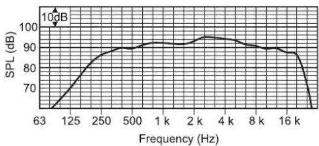
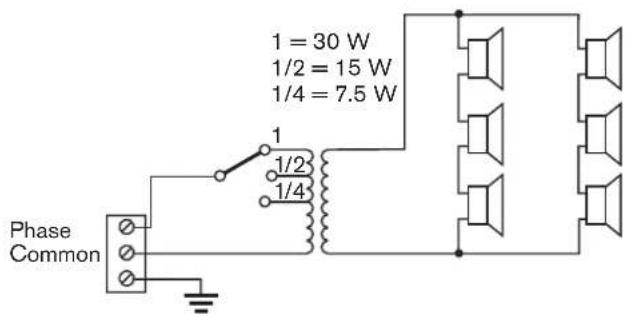
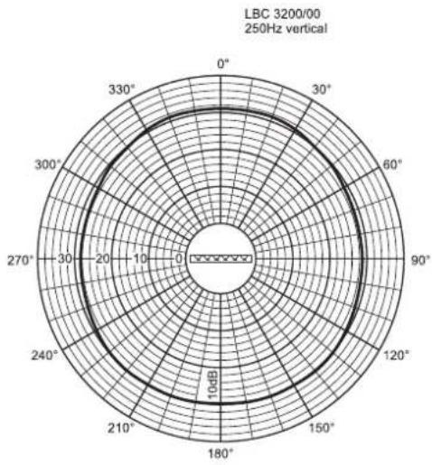
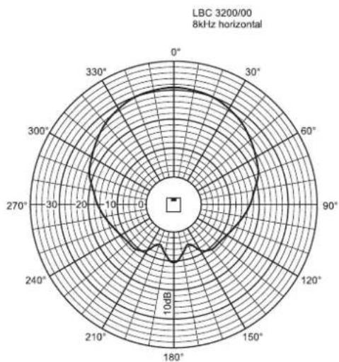
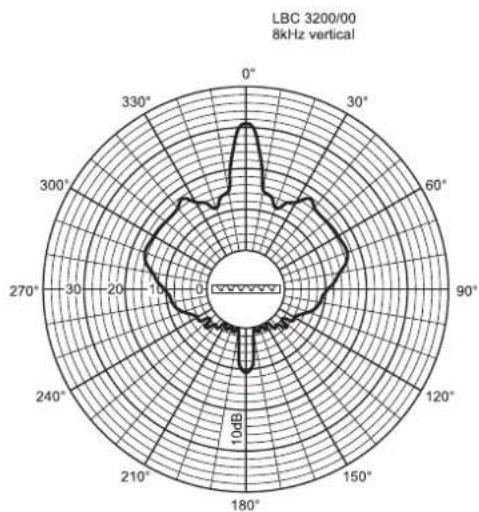
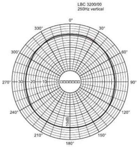
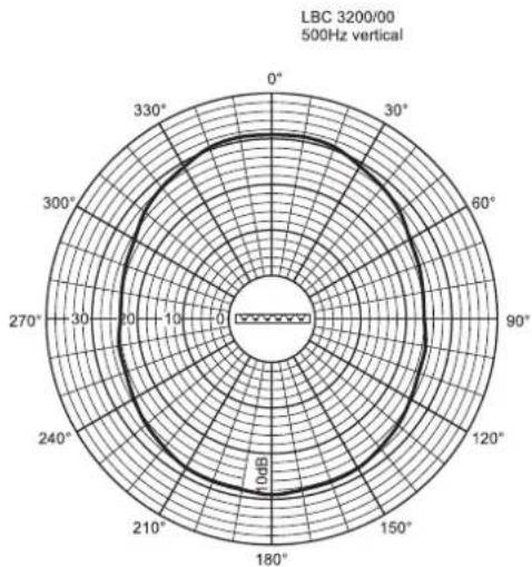
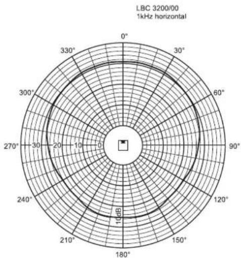
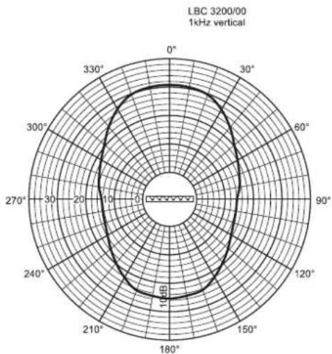
LBC 3200/00
| Octave band (Hz) 250 500 1 k 2 k 4 k 8 k | ||||||||||
| S | P | L | 1 | . | 1 | 87 | 8 | 9 | ||
| SPL max. | 102 | 104 | 106 | 108 | 108 | 104 | ||||
| Q-factor | 1.3 | 2.2 | 4.5 | 11.6 | 25.7 | 58.9 | ||||
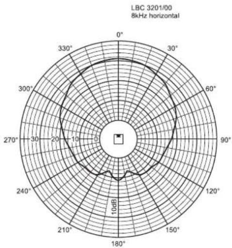
| Hor. Angle (deg) | 360 | 360 | 220 | 190 | 130 | 100 | ||||
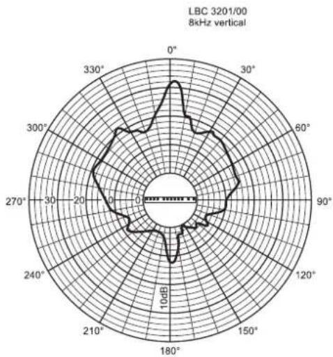
| Vert. Angle (deg) | 360 | 120 | 70 | 32 | 18 | 10 | ||||
Horizontal Vertical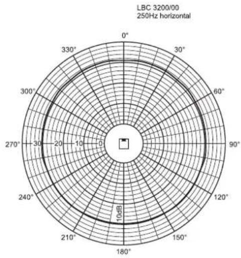
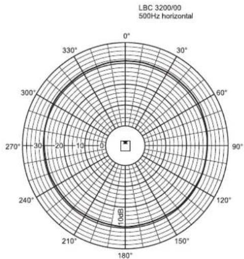
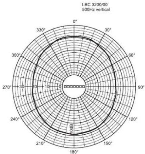
Horizontal Vertical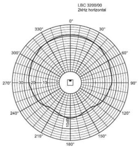
TECHNICAL PERFORMANCE DATA
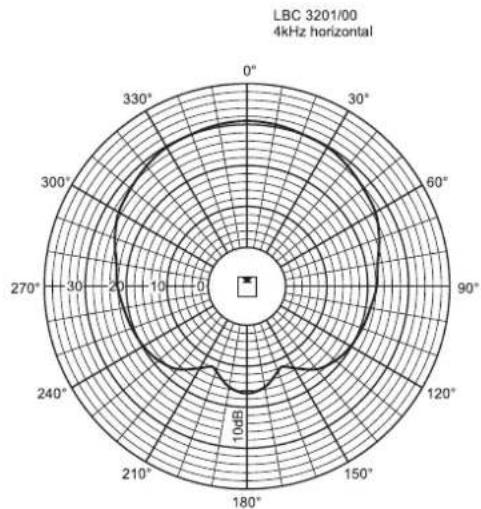
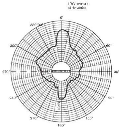
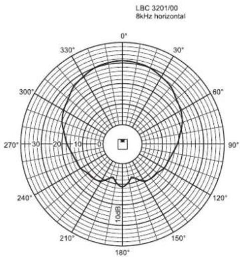
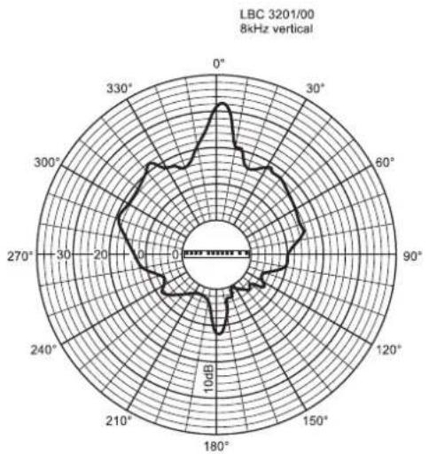
| LBC 3201/00 | |
| Maximum power 90 W | |
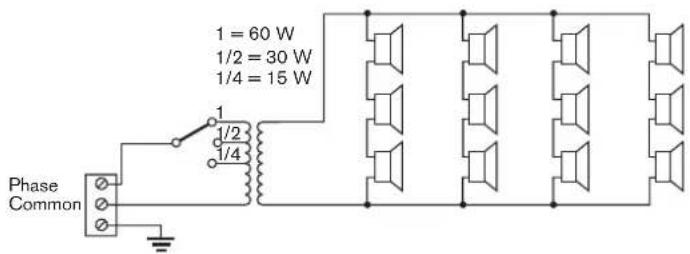
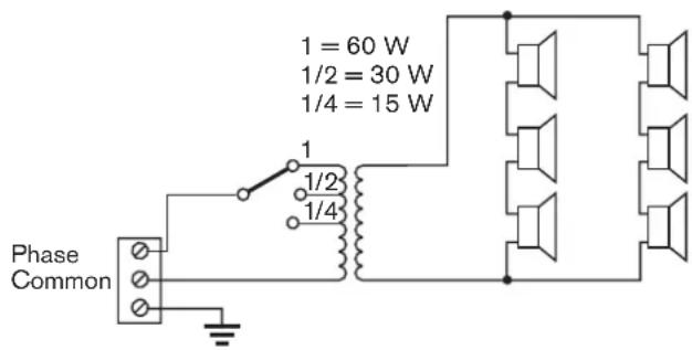
| Rated power 60 W (60-30-15 W) | |
| Sound pressure level at | |
| 60 W/1 W (at 1 kHz, 1 m) 110 dB/92 dB (SPL) | |
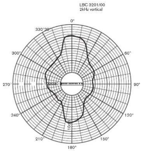
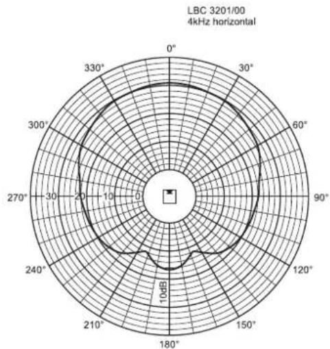
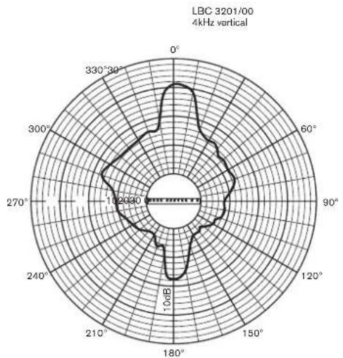
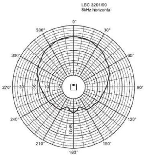
| Effective frequency range (-10 dB) | 190 Hz to 18 kHz |
| Opening angle | |
| (at 1 kHz / 4 kHz, - 6 dB) | |
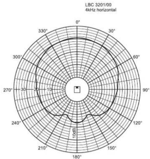
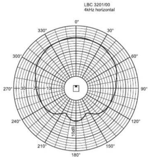
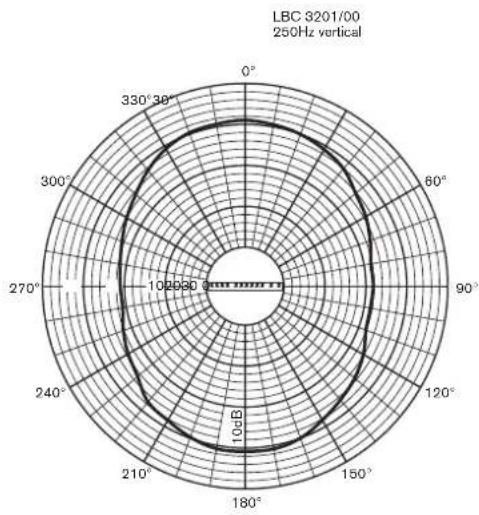
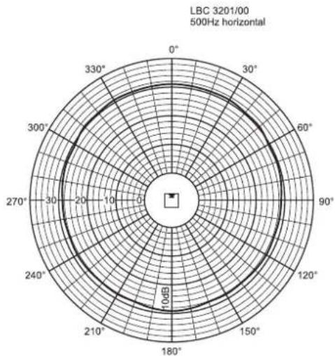
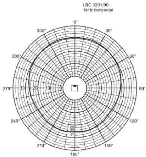
| Horizontal | 210°/132° |
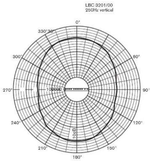
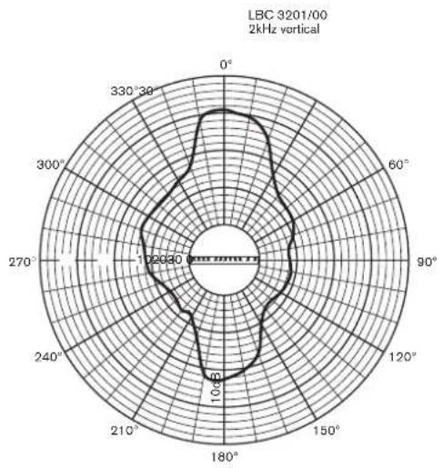
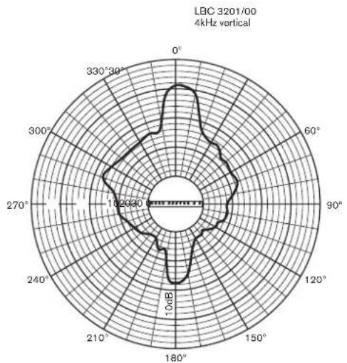
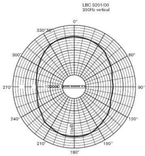
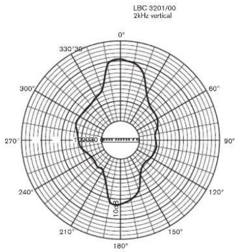
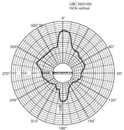
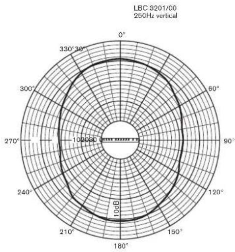
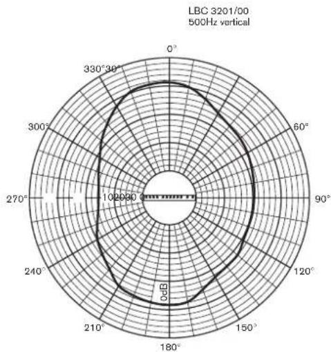
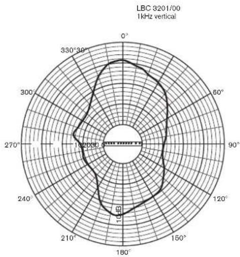
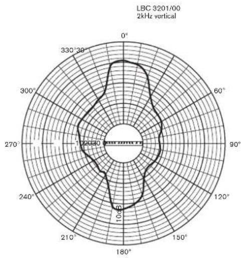
| Vertical | 50°/22° |
| Rated input voltage | 100 V |
| Rated impedance | 167 ohm |
| Ambient temperature range | -25°C to +55°C |
| Safety | according to EN 60065. |
| Connection | screw terminal block |
| Dimensions (H x W x D) | 1200 x 80 x 90 mm |
| Colour | silver |
| Weight | 6,4 kg |
LBC 3201/00
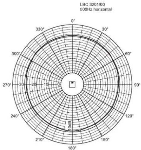
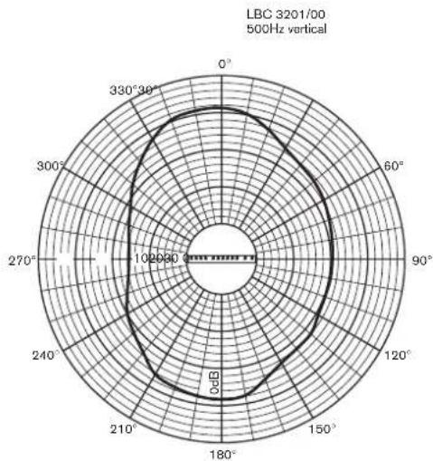
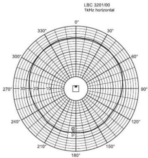
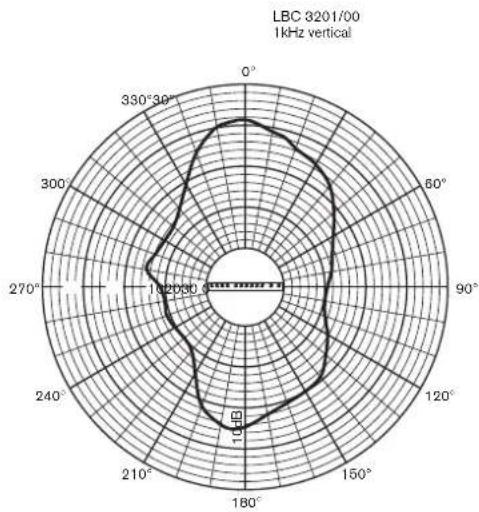
| Octave band (Hz) | 250 | 500 | 1 k | 2 k | 4 k | 8 k |
| SPL 1.1 | 88 | 92 | 92 | 91 | 91 | 86 |
| SPL max. | 106 | 110 | 110 | 109 | 109 | 104 |
| Q-factor | 2.2 | 3.2 | 6.5 | 12.6 | 23.4 | 53.3 |
| Hor. Angle (deg) | 360 | 360 | 210 | 192 | 132 | 100 |
| Vert. Angle (deg) | 107 | 67 | 50 | 33 | 22 | 12 |
Horizontal Vertical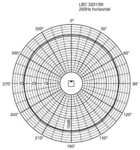
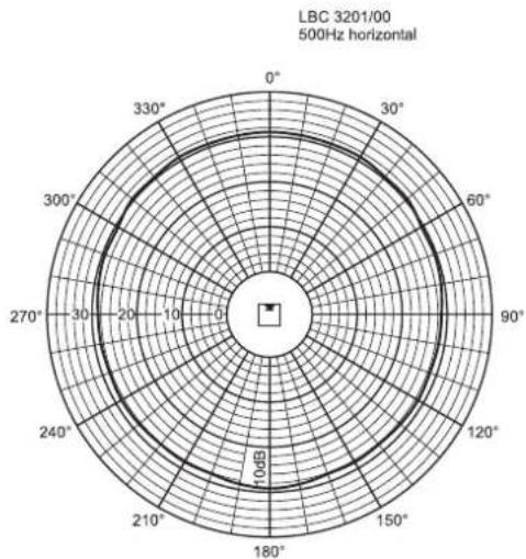
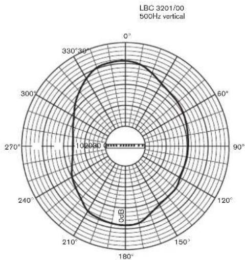
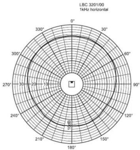
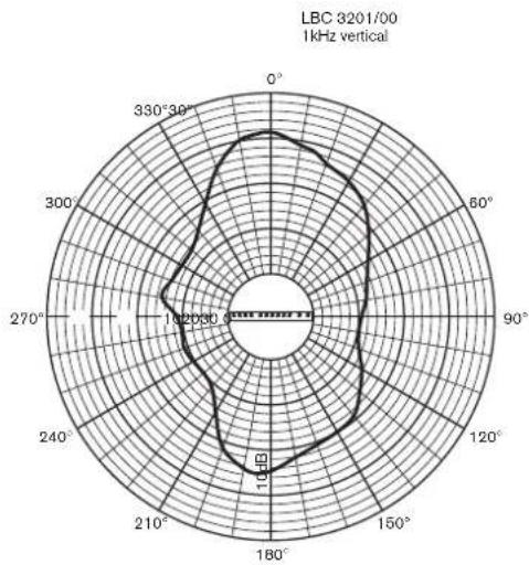
Horizontal Vertical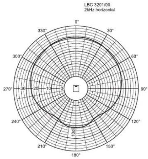
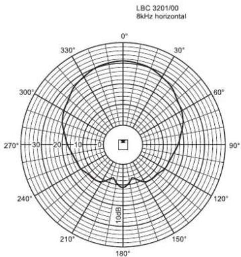
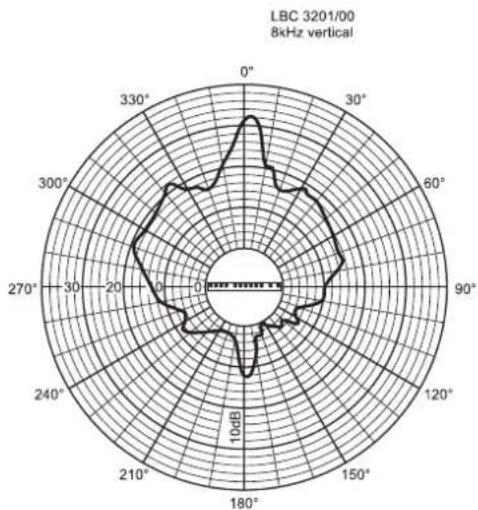
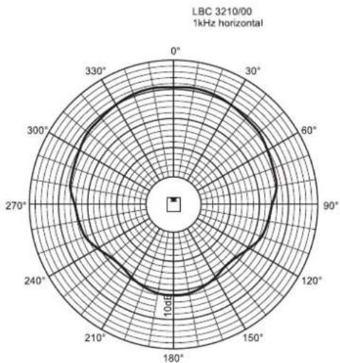
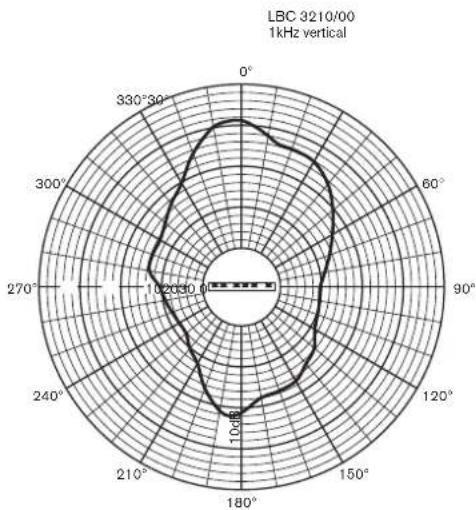
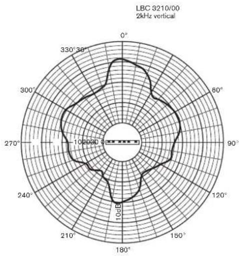
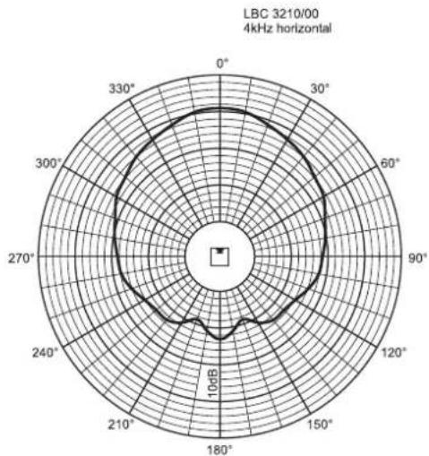
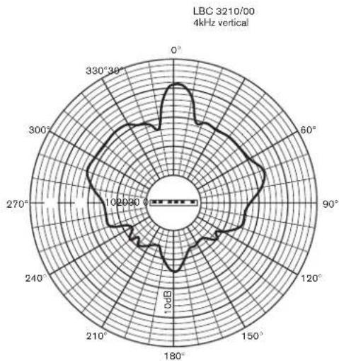
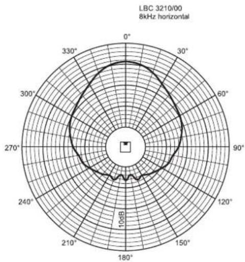
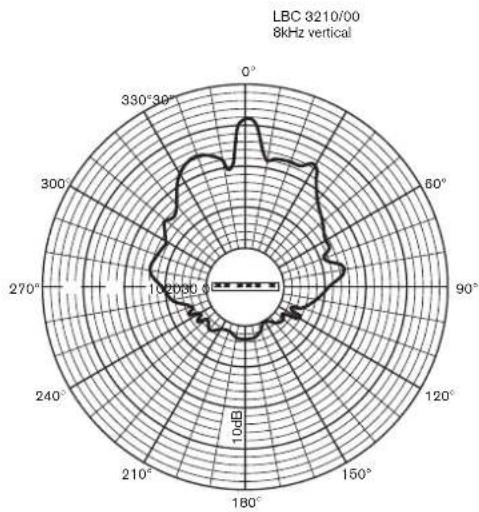
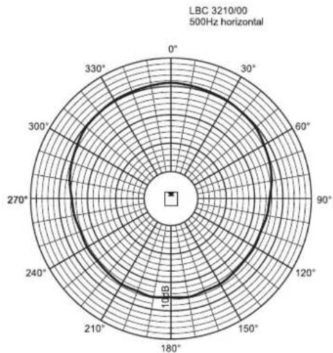
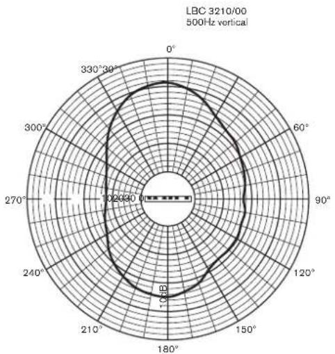
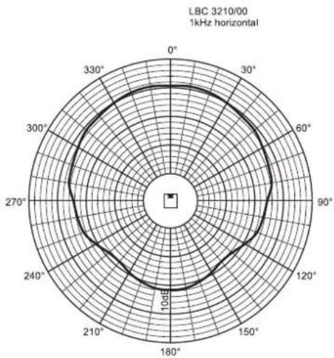
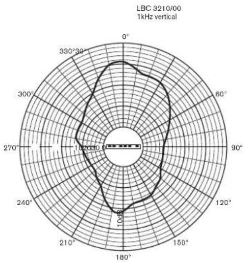
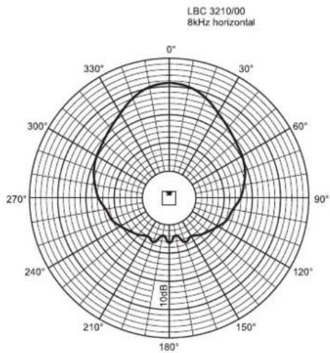
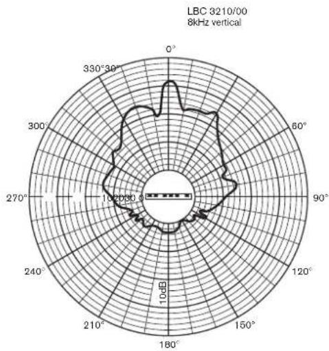
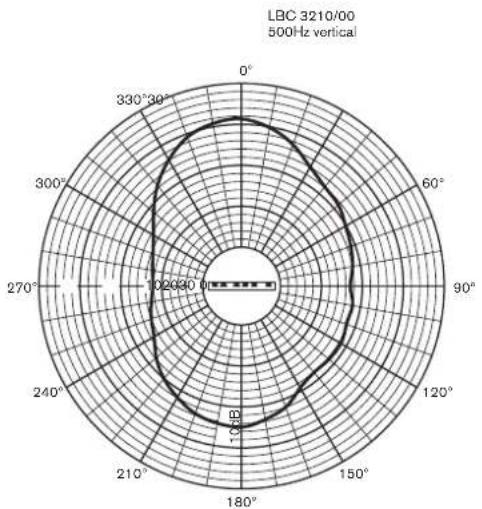
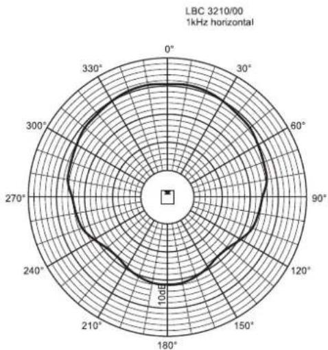
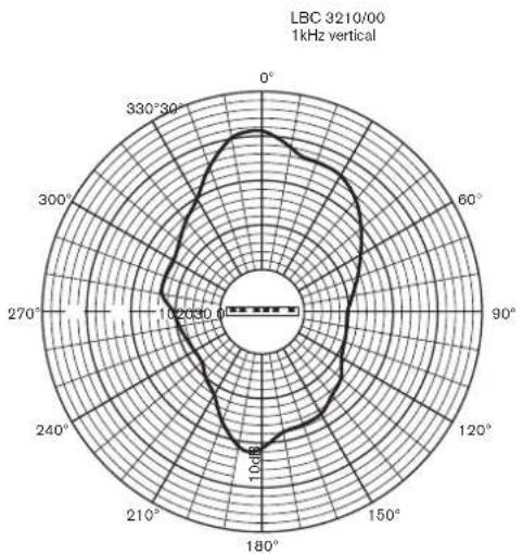
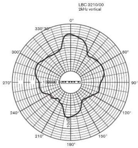
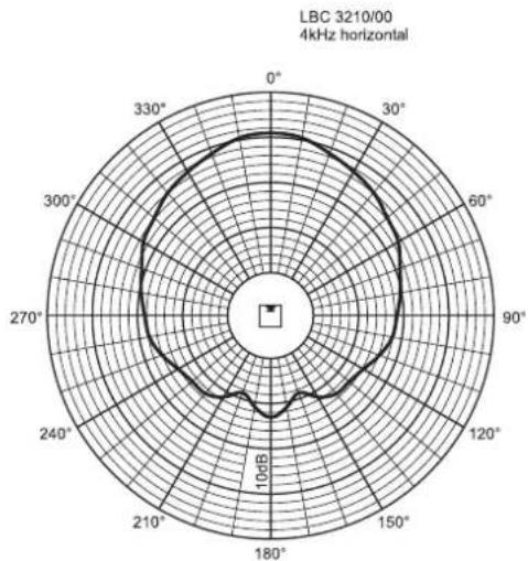
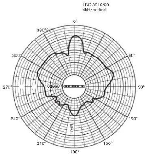
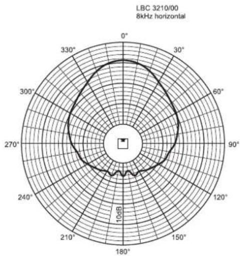
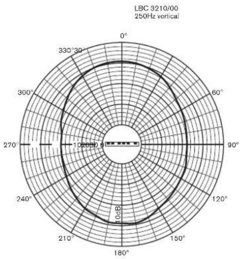
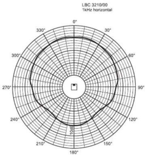
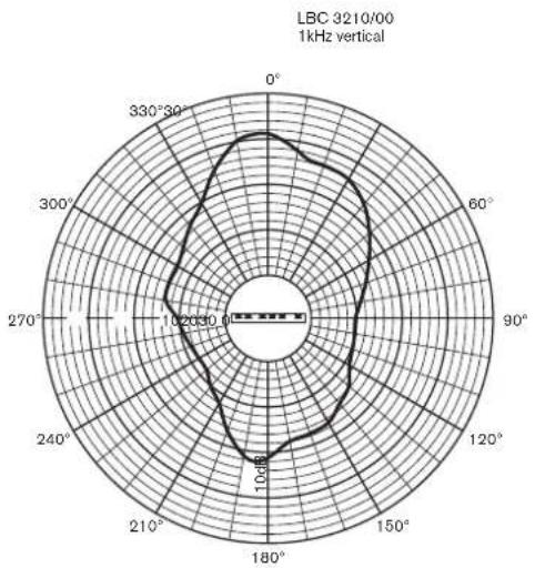
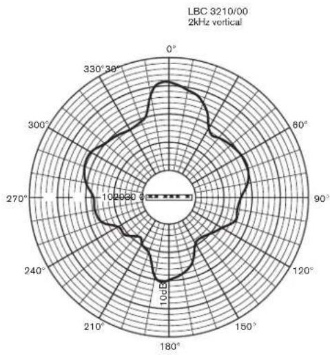
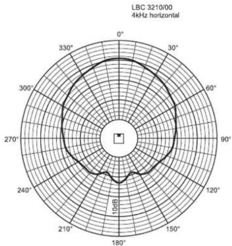
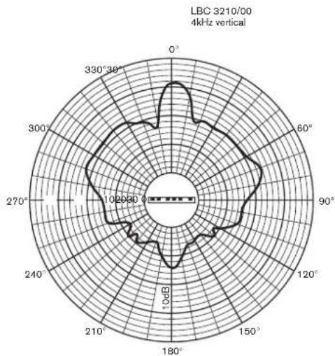
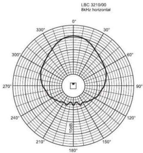
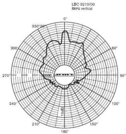
TECHNICAL PERFORMANCE DATA LBC 3210/00 Maximum power 90 W Rated power 60 W (60-30-15 W) Sound pressure level at 60 W/1 W (at 1 kHz, 1 m) 115 dB/97 dB (SPL) Effective frequency range (-10 dB) 190 Hz to 20 kHz Opening angle (at 1 kHz / 4 kHz, - 6 dB)
| Horizontal | 170°/90° |
| Vertical | 55°/18° |
| Rated input voltage | 100 V |
| Rated impedance | 167 ohm |
Ambient temperature range -25°C to +55°C
| Safety | according to EN 60065. |
| Water/dust protection | IP 66 according to IEC 60529 |
| Connection | screw terminal block |
| Dimensions (H x W x D) | 1200 x 160 x 90 mm |
| Colour | silver |
| Weight | 9 kg |
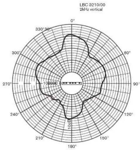
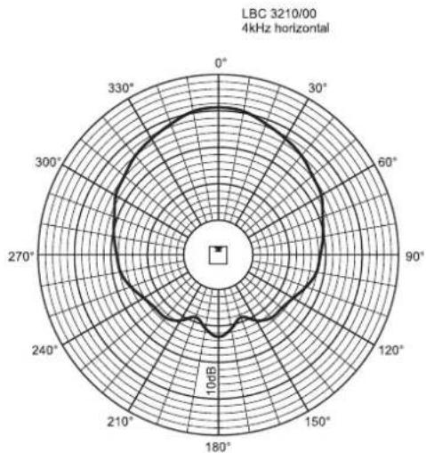
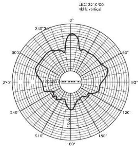
LBC 3210/00
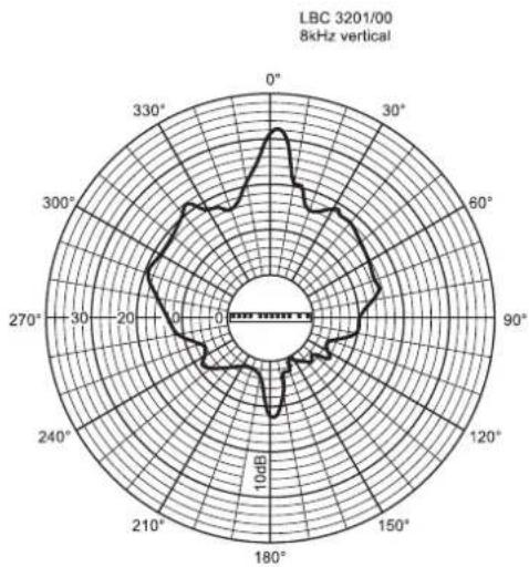
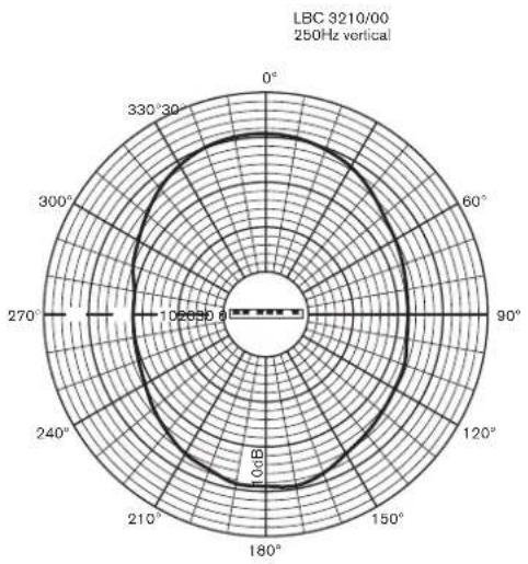
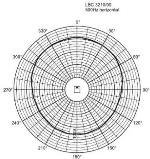
| Octave band (Hz) | 250 | 500 | 1 k | 2 k | 4 k | 8 k |
| SPL 1.1 | 94 | 97 | 97 | 95 | 96 | 93 |
| SPL max. | 112 | 115 | 115 | 113 | 114 | 111 |
| Q-factor | 2.2 | 2.7 | 6.3 | 10.8 | 22.6 | 32.3 |
| Hor. Angle (deg) | 360 | 180 | 170 | 160 | 90 | 60 |
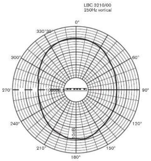
| Vert. Angle (deg) | 100 | 60 | 55 | 34 | 18 | 10 |
Horizontal Vertical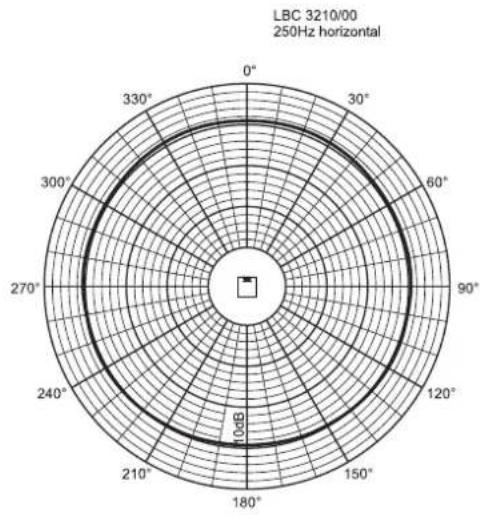
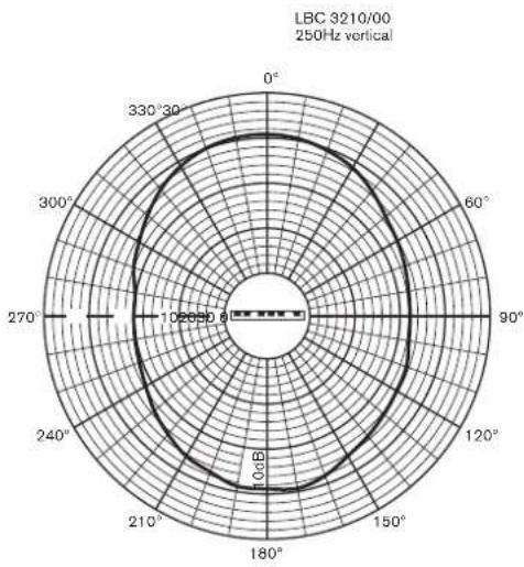
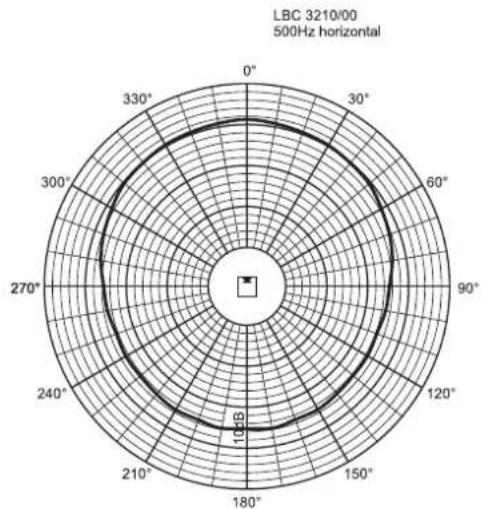
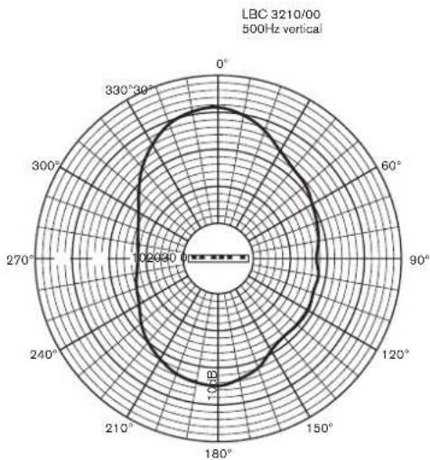
Horizontal Vertical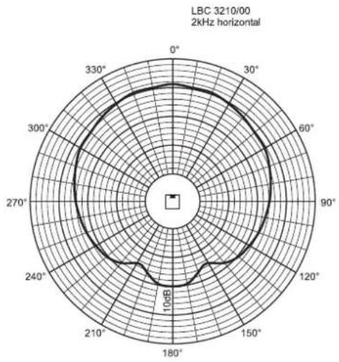
www.boschsecuritysystems.com
BOSCH
Sommaire Page
Guide d'installation (fig. 1 - fig. 17) ......28
LBC 3200/00
LBC 3201/00
LBC 3210/00
LBC 3200/00
| Oktavband (Hz) 250 500 1 k 2 k 4 k 8 k | ||||||
| Schalldruckpegel 1 W,1 m 87 89 91 93 | 93 89 | |||||
| Schalldruckpegel max. | 102 | 104 | 106 | 108 | 108 | 104 |
| Q-Faktor | 1.3 | 2.2 | 4,5 | 11,6 | 25,7 | 58,9 |
| Hor. Winkel (Grad) | 360 | 360 | 220 | 190 | 130 | 100 |
| Vert. Winkel (Grad) | 360 | 120 | 70 | 32 | 18 | 10 |
Horizontal Vertical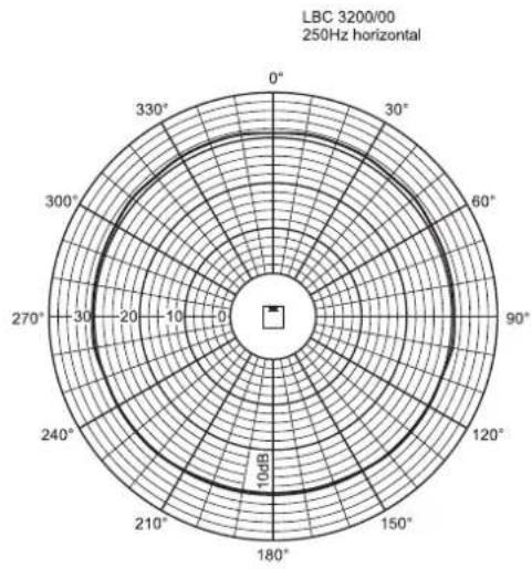
Horizontal Vertical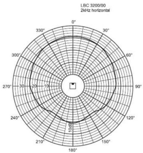
LBC 3201/00
| Oktavband (Hz) | 250 | 500 | 1 k | 2 k | 4 k | 8 k |
| Schalldruckpegel 1 W,1 m | 88 | 92 | 92 | 91 | 91 | 86 |
| Schalldruckpegel max. | 106 | 110 | 110 | 109 | 109 | 104 |
| Q-Faktor | 2.2 | 3.2 | 6.5 | 12,6 | 23,4 | 53,3 |
| Hor. Winkel (Grad) | 360 | 360 | 210 | 192 | 132 | 100 |
| Vert. Winkel (Grad) | 107 | 67 | 50 | 33 | 22 | 12 |
Horizontal Vertical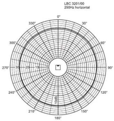
Horizontal Vertical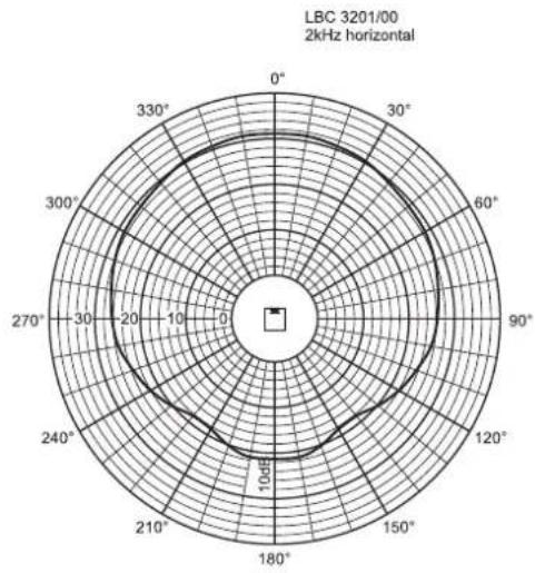
LBC 3210/00
| Oktavband (Hz) | 250 | 500 | 1 k | 2 k | 4 k | 8 k |
| Schalldruckpegel 1 W,1 m | 94 | 97 | 97 | 95 | 96 | 93 |
| Schalldruckpegel max. | 112 | 115 | 115 | 113 | 114 | 111 |
| Q-Faktor | 2.2 | 2.7 | 6.3 | 10,8 | 22,6 | 32,3 |
| Hor. Winkel (Grad) | 360 | 180 | 170 | 160 | 90 | 60 |
| Vert. Winkel (Grad) | 100 | 60 | 55 | 34 | 18 | 10 |
Horizontal Vertical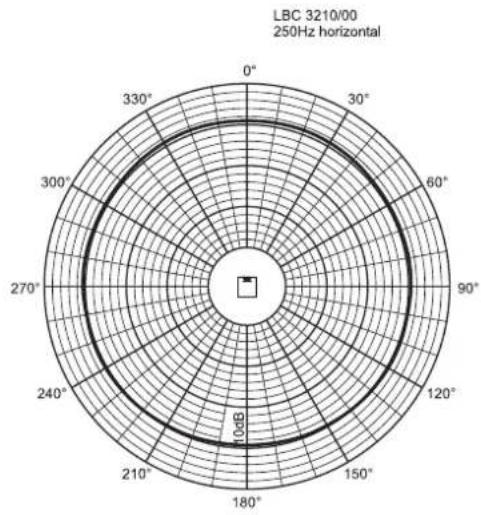
Horizontal Vertical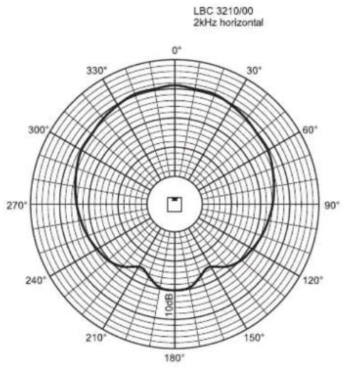
www.boschsecuritysystems.com
BOSCH
Index Page
LBC 3200/00
| Banda de octavas (Hz) 250 500 1 k 2 k 4 k 8 k | ||||||
| NPA 1,1 | 87 | 89 | 91 | 93 | 93 | 89 |
| NPA máx. | 102 | 104 | 106 | 108 | 108 | 104 |
| Factor Q | 1,3 | 2,2 | 4,5 | 11,6 | 25,7 | 58,9 |
| Ángulo horizontal (grados) | 360 | 360 | 220 | 190 | 130 | 100 |
| Ángulo vertical (grados) | 360 | 120 | 70 | 32 | 18 | 10 |
Horizontal Vertical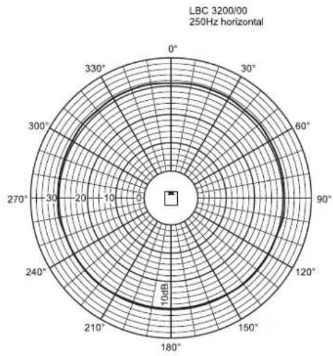
Horizontal Vertical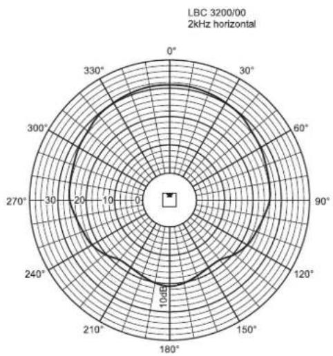
LBC 3201/00
| Banda de octavas (Hz) | 250 | 500 | 1 k | 2 k | 4 k | 8 k |
| NPA 1,1 | 88 | 92 | 92 | 91 | 91 | 86 |
| NPA máx. | 106 | 110 | 110 | 109 | 109 | 104 |
| Factor Q | 2,2 | 3,2 | 6,5 | 12,6 | 23,4 | 53,3 |
| Ángulo horizontal (grados) | 360 | 360 | 210 | 192 | 132 | 100 |
| Ángulo vertical (grados) | 107 | 67 | 50 | 33 | 22 | 12 |
Horizontal Vertical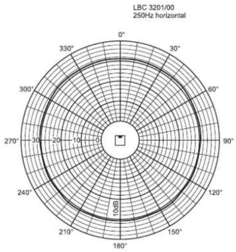
Horizontal Vertical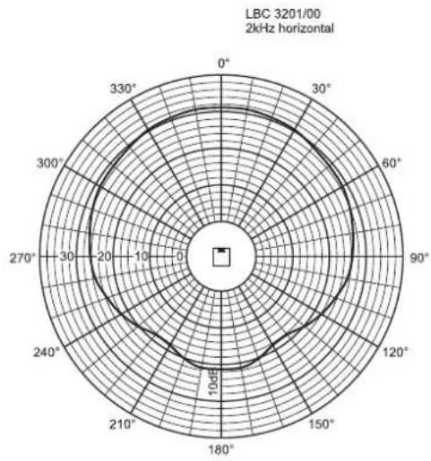
LBC 3210/00
| Banda de octavas (Hz) | 250 | 500 | 1 k | 2 k | 4 k | 8 k |
| NPA 1,1 | 94 | 97 | 97 | 95 | 96 | 93 |
| NPA máx. | 112 | 115 | 115 | 113 | 114 | 111 |
| Factor Q | 2,2 | 2,7 | 6,3 | 10,8 | 22,6 | 32,3 |
| Ángulo horizontal (grados) | 360 | 180 | 170 | 160 | 90 | 60 |
| Ángulo vertical (grados) | 100 | 60 | 55 | 34 | 18 | 10 |
Horizontal Vertical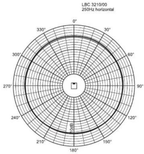
Horizontal Vertical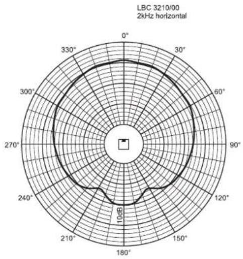
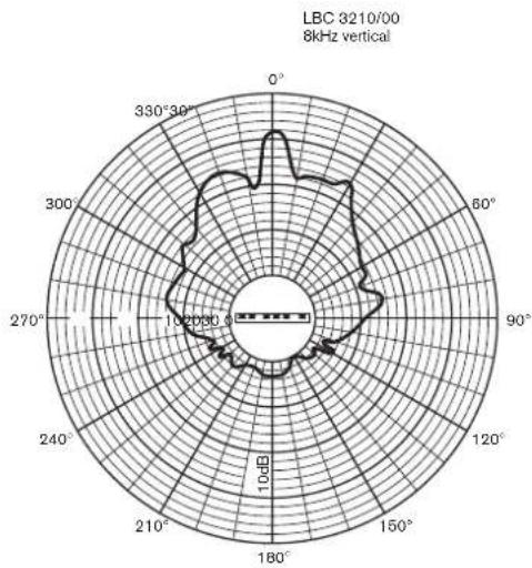
www.boschsecuritysystems.com
BOSCH
Table of Contents Page
LBC 3200/00
| Octaafband (Hz) 250 500 1 k 2 k 4 k 8 k | ||||||||
| S | P | L | 1 | . | 1 | 87 | 8 | 9 |
| SPL max. | 102 | 104 | 106 | 108 | 108 | 104 | ||
| Q-factor | 1,3 | 2,2 | 4,5 | 11,6 | 25,7 | 58,9 | ||
| Hor. hoek (graden) | 360 | 360 | 220 | 190 | 130 | 100 | ||
| Vert. hoek (graden) | 360 | 120 | 70 | 32 | 18 | 10 | ||
LBC 3201/00
| Octaafband (Hz) | 250 | 500 | 1 k | 2 k | 4 k | 8 k |
| SPL 1.1 | 88 | 92 | 92 | 91 | 91 | 86 |
| SPL max. | 106 | 110 | 110 | 109 | 109 | 104 |
| Q-factor | 2,2 | 3,2 | 6,5 | 12,6 | 23,4 | 53,3 |
| Hor. hoek (graden) | 360 | 360 | 210 | 192 | 132 | 100 |
| Vert. hoek (graden) | 107 | 67 | 50 | 33 | 22 | 12 |
LBC 3210/00
| Octaafband (Hz) | 250 | 500 | 1 k | 2 k | 4 k | 8 k |
| SPL 1.1 | 94 | 97 | 97 | 95 | 96 | 93 |
| SPL max. | 112 | 115 | 115 | 113 | 114 | 111 |
| Q-factor | 2,2 | 2,7 | 6,3 | 10,8 | 22,6 | 32,3 |
| Hor. hoek (graden) | 360 | 180 | 170 | 160 | 90 | 60 |
| Vert. hoek (graden) | 100 | 60 | 55 | 34 | 18 | 10 |
LBC 3200/00
| Banda d'ottava (Hz) 250 500 1 k 2 k 4 k 8 k | ||||||||||
| S | P | L | 1 | . | 1 | 8 | 7 | 8 | ||
| SPL max | 102 | 104 | 106 | 108 | 108 | 104 | ||||
| Fattore Q | 1.3 | 2.2 4.5 11.6 | 25.7 58.9 | |||||||
| Angolo orizzontale (gradi) | 360 | 360 | 220 | 190 | 130 | 100 | ||||
| Angolo verticale (gradi) | 360 | 120 | 70 | 32 | 18 | 10 | ||||
LBC 3201/00
| Banda d'ottava (Hz) | 250 | 500 | 1 k | 2 k | 4 k | 8 k |
| SPL 1.1 | 88 | 92 | 92 | 91 | 91 | 86 |
| SPL max | 106 | 110 | 110 | 109 | 109 | 104 |
| Fattore Q | 2,2 | 3,2 | 6,5 | 12,6 | 23,4 | 53,3 |
| Angolo orizzontale (gradi) | 360 | 360 | 210 | 192 | 132 | 100 |
| Angolo verticale (gradi) | 107 | 67 | 50 | 33 | 22 | 12 |
LBC 3210/00
| Banda d'ottava (Hz) | 250 | 500 | 1 k | 2 k | 4 k | 8 k |
| SPL 1.1 | 94 | 97 | 97 | 95 | 96 | 93 |
| SPL max | 112 | 115 | 115 | 113 | 114 | 111 |
| Fattore Q | 2,2 | 2,7 | 6,3 | 10,8 | 22,6 | 32,3 |
| Angolo orizzontale (gradi) | 360 | 180 | 170 | 160 | 90 | 60 |
| Angolo verticale (gradi) | 100 | 60 | 55 | 34 | 18 | 10 |
LBC 3200/00
| Banda de oitavas (Hz) 250 500 1 k 2 k 4 k 8 k | ||||||||||
| S | P | L | 1 | . | 1 | 8 | 7 | 8 | ||
| SPL máx. | 102 | 104 | 106 | 108 | 108 | 104 | ||||
| Factor Q | 1,3 | 2,2 | 4,5 | 11,6 | 25,7 | 58,9 | ||||
| Ângulo horizontal (graus) | 360 | 360 | 220 | 190 | 130 | 100 | ||||
| Ângulo vertical (graus) | 360 | 120 | 70 | 32 | 18 | 10 | ||||
Horizontal Vertical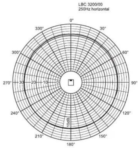
Horizontal Vertical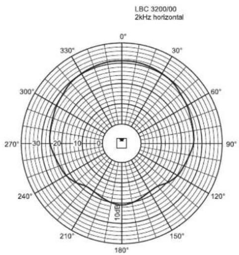
PERFORMANCE TECHNICAL DATA
LBC 3201/00
| Banda de oitavas (Hz) | 250 | 500 | 1 k | 2 k | 4 k | 8 k | |
| SPL 1.1 | 88 | 92 | 92 | 91 | 91 | 86 | |
| SPL máx. | 106 | 110 | 110 | 109 | 109 | 104 | |
| Factor Q | 2,2 | 3,2 | 6,5 | 12,6 | 23,4 | 53,3 | |
| Ângulo horizontal (graus) | 360 | 360 | 210 | 192 | 132 | 100 | |
| Ângulo vertical (graus) | 107 | 67 | 50 | 33 | 22 | 12 |
Horizontal Vertical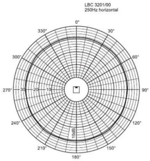

Horizontal Vertical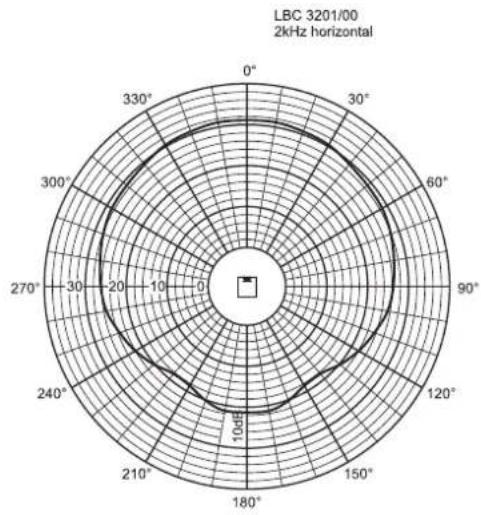
PERFORMANCE TECHNICAL DATA
LBC 3210/00
| Banda de oitavas (Hz) | 250 | 500 | 1 k | 2 k | 4 k | 8 k | ||
| SPL 1.1 | 94 | 97 | 97 | 95 | 96 | 93 | ||
| SPL máx. | 112 | 115 | 115 | 113 | 114 | 111 | ||
| Factor Q 2,2 2,7 | 6,3 | 10,8 | 22,6 32,3 | |||||
| Ângulo horizontal (graus) | 360 | 180 | 170 | 160 | 90 | 60 | ||
| Ângulo vertical (graus) | 100 | 60 | 55 | 34 | 18 | 10 |
Horizontal Vertical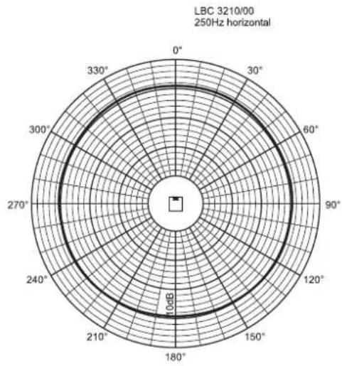
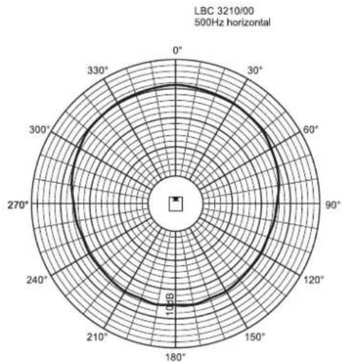
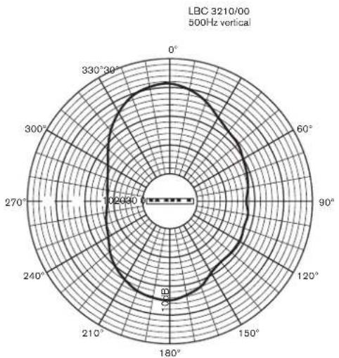
Horizontal Vertical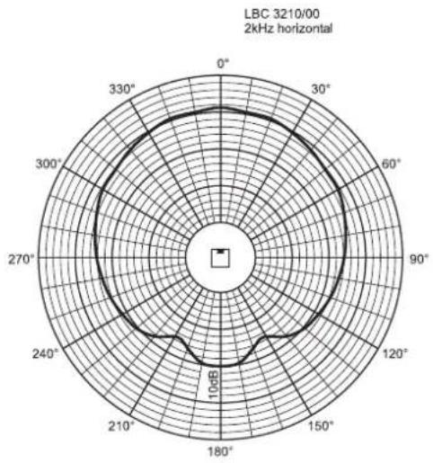
www.boschsecuritysystems.com
BOSCH
www.boschsecuritysystems.com
BOSCH

- SECURITY SYSTEMS
- CONTENTS PAGE
- LISTENING AREA AND RELATED MOUNTING HEIGHT FOR XLA
- DETERMINING MOUNTING HEIGHT AND ANGLE FOR THE LBC3200 LOUDSPEAKER ARRAY
- INSTALLATION QUESTIONS AND ANSWERS
- MAY I INSTALL THE LBC3200 LOUDSPEAKER ARRAY THE SAME AS LBC3210 OR LBC
- IF I CANNOT SEE THE LOUDSPEAKER ARRAY, DOES IT MEAN THAT I CANNOT HEAR HIGH TONES
- BACKGROUND INFORMATION
- HOW TO USE THESE MOUNTING METHOD
- EXAMPLE
- DIAGONAL LINE MEANINGS
- HOW TO USE THESE MOUNTING METHODS
- DIAGRAM EXAMPLE
- LINE MEANING
- SOMMAIRE PAGE
- INDEX PAGE
- TABLE OF CONTENTS PAGE
Brand : BOSCH
Model : XLA 3200
Category : Loudspeaker