
IAN 110595 - Lighting Livarno Lux - Free user manual and instructions
Find the device manual for free IAN 110595 Livarno Lux in PDF.


User questions about IAN 110595 Livarno Lux
0 question about this device. Answer the ones you know or ask your own.
Ask a new question about this device
Download the instructions for your Lighting in PDF format for free! Find your manual IAN 110595 - Livarno Lux and take your electronic device back in hand. On this page are published all the documents necessary for the use of your device. IAN 110595 by Livarno Lux.
USER MANUAL IAN 110595 Livarno Lux
natural_image
Product display of a ceiling-mounted LED fixture with three recessed lighting fixtures, shown from three angles (top, front, side) and a watermark (no text on main components)LED-WAND-/DECKENLEUCHTE
DE AT CH
LED-WAND-/DECKENLEUCHTE
Assembly, operating and safety instructions
IAN 110595
DE AT CH
Before reading, unfold the page containing the illustrations and familiarise yourself with all functions of the device.
GB Assembly, operating and safety instructions Page 23
text_image
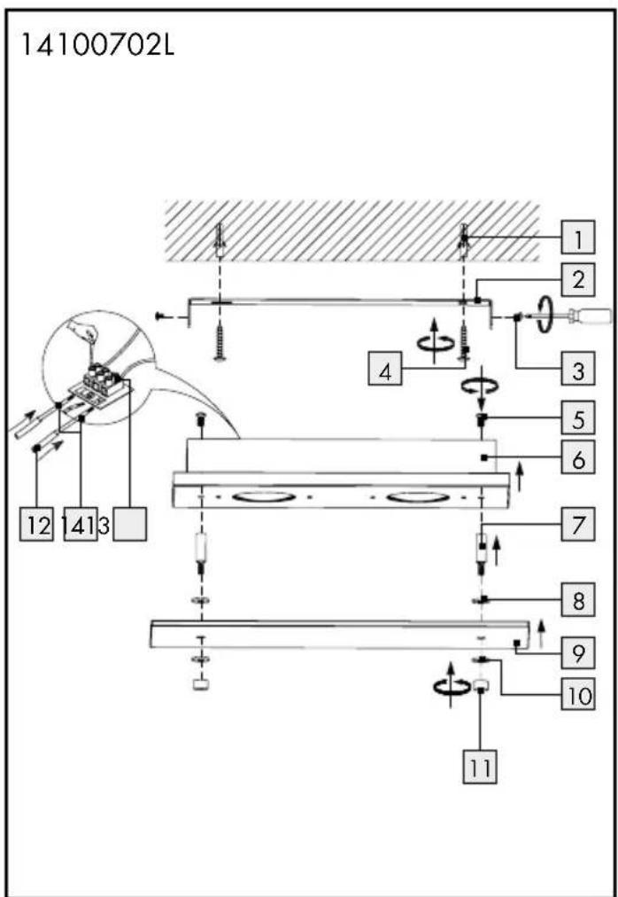
14100702L 1 2 3 4 5 6 7 8 9 10 11 12 1413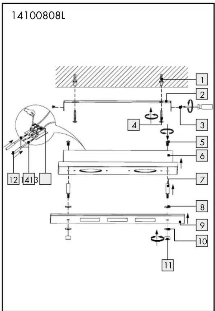
text_image
14100808L 1 2 3 4 5 6 7 8 9 10 11 12 13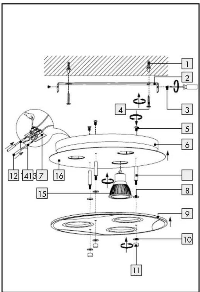
text_image
Technical diagram of a ceiling lamp installation with numbered components and labeled parts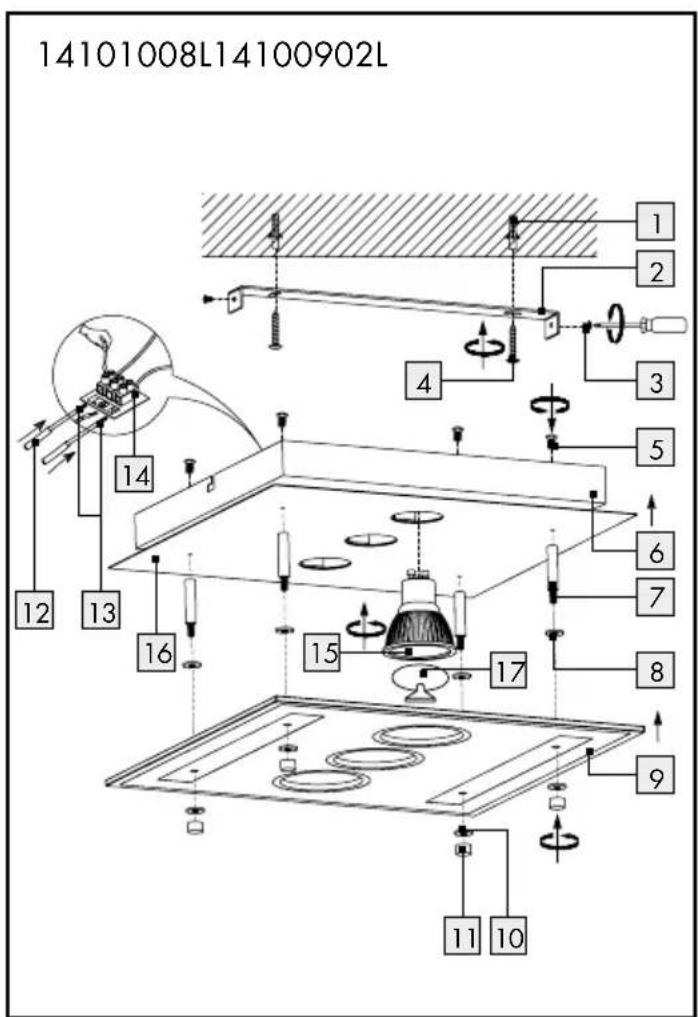
text_image
14101008L14100902L 1 2 3 4 5 6 7 8 9 10 11 12 13 14 15 16Einleitung
Intended use Page 24
Scope of delivery Page 24
Parts description Page 24
Technical Data Page 24
Safety
Safety notices Page 25
Preparation
Required tools and material....Page 25
Prior to installation Page 26
Start-up
Mounting the light....Page 26
Replacing lamps....Page 27
Maintenance and Cleaning......Page 27
Disposal Page 27
Warranty and Service
Warranty Declaration......Page 27
Service address......Page 28
Declaration of conformity....Page 28
Manufacturer......Page 28
LED Wall/Ceiling light
Introduction
Congratulations on your new product.
You have selected a high quality product. Please be sure to carefully read the complete operating instructions. Fold out the page with the illustrations. These instructions are part of the product and contain important information on setup and handling. Always follow all safety instructions. Before using this product for the first time verify the correct voltage and that all parts are properly installed. Should you have any questions or you are unsure about operating the product, please contact the dealer or service centre. Please keep these instructions in a safe place and pass them on to third parties as applicable.
Intended use
This light is only suitable for indoor use in dry and enclosed spaces. The light can be fastened to any normally inflammable surface. This product is intended for private household use only.
- Scope of delivery
Check immediately after unpacking that the parts are complete and that the product is in proper condition.
1 LED Wall / Ceiling light, model 14100702L or 14100808L or 14100902L or 14101008L
3 LED lamp GU10, 2.7 W (14100902L or 14101008L)
1 Glass plate
1 Chrome plating (14100902L or 14101008L)
2 Protective tubes
4 Silicone rings (14100702L or 14100808L)
6 Silicone rings (14100902L)
8 Silicone rings (14101008L)
2 Box nuts (14100702L or 14100808L)
3 Box nuts (14100902L)
4 Box nuts (14101008L)
2 Spacers (14100702L or 14100808L)
3 Spacers (14100902L)
4 Spacers (14101008L)
2 Screws (spacer) (14100702L or 14100808L)
3 Screws (spacer) (14100902L)
4 Screws (spacer) (14101008L)
2 Screws (mounting angle)
2 Dowel
1 Suction cup (14101008L)
1 Instructions for assembly and use
- Parts description
1 Rawlplug
2 Mounting bracket
3 Locating screws (connection housing)
4 Screws (mounting bracket)
5 Screws (spacer)
6 Connection housing
7 Distance support
8 Silicone rings
9 Glass plate
10 Silicone rings
11 Box nut
12 Protective tube
13 Mains connection cable (external)
14 Terminal block
15 Lamps (14100902L or 14101008L)
16 Chrome plating
17 Suction cup
- Technical Data
Item no.: 14100702L or 14100808L or
14100902L or 14101008L
Operating voltage: 230 V\~, 50 Hz (14100702L or
14100808L) or 230-240 V\~,
50 Hz (14100902L or
14101008L)
Lamp: 14100702L or 14100808L:
2 x LED module, 5 W
14100902L or 14101008L:
3 x GU10, LED, 2.7 W
Protection class: I/

Protection type: IP20
Safety

Safety notices
Damage due to failure to comply with these operating instructions will invalidate the warranty! We assume no liability for consequential damage! We assume no liability for material damage or personal injury due to improper handling or failure to comply with the safety instructions!
Do not leave the light or packaging material lying unattended. Plastic film or bags, plastic parts, etc. can be dangerous for children to play with.

Avoid the risk of fatal injury from electric shock
■ Ensure that a qualified electrician, or a person trained to carry out electrical installations, performs the electrical installation.
Always check the light, power supply, and mains cable for damage before plugging it in. Never use the light if it shows any signs of damage.
CAUTION! A damaged mains cable indicates a life-threatening danger due to electric shock. In the event of damage, repairs or other problems with the light please contact the service centre or a qualified electrician.
Prior to installation, remove the fuse or switch off the circuit breaker (0 setting) in the fuse box.
Prior to installation, verify the available mains voltage corresponds with the operating voltage required for the light (230 V\~ (14100702L or 14100808L) or 230-240 V\~ (14100902L or 14101008L)).
■ Ensure that the light does not come into contact with water or other liquids under any circumstances.
Never open any of the components of the electrical equipment or insert any objects into the same components. This will pose a risk of fatal injury from electric shock.
Do not install the light on a wet or conductive substrate!
The connecting leads must be covered with the included rounding wires.

Prevent fire and injury hazards
RISK OF INJURY! Check each lamp and lamp glass for damage immediately after unpacking.
- Do not mount the light with defective lamps and / or lamp lenses. Should this be the case, contact the service centre for a replacement.
- Do not look directly into the light source (lamp, LED etc.).
RISK OF BURNS! Ensure the light has been switched off and has cooled before touching it to avoid burns.
Lights develop a lot of heat around the lamp head.
Allow the light to cool off completely.
- Replace defective bulbs with new ones immediately. Before changing lamps, always first remove the fuse or switch off the circuit breaker.

Safe working
Only use 220-240 V\~ LED lamps with a GU10 base and a maximum output of 2.7 W (14100902L or 14101008L).
Mount the light so that it is protected from moisture and dirt.
Carefully prepare for assembly and allow yourself adequate time. Organise all parts and any necessary additional tools or materials before starting so they are easy to reach.
Always be attentive! Always pay attention to what you are doing and use common sense. Never install the light if you are having difficulty concentrating or do not feel well.
● Preparation
- Required tools and material
The tools and materials specified are not included. This information and these values are non-binding
and are only provided as a reference. The nature of the material is determined by the individual local conditions.
- Pencil / marking tool
- Voltage tester
- Screwdriver
- Electric drill
- Drill (ø 6 mm)
- Side cutting pliers
- Ladder
- Prior to installation
Important: The electrical connection must be performed by a qualified electrician or a person trained in electrical installations. This person must be familiar with the properties of the light and the connection regulations.
Familiarise yourself with all the instructions and diagrams in this manual, as well as with the light itself, before you install it.
Before installation ensure that the circuit, to which the light will be connected, is not energised. To do so, remove the fuse or switch off the circuit breaker in the fuse box 0 position.
☐ Use the voltage tester to verify the de-energised status.
Start-up
Mounting the light
Model 14100702L or 14100808L
Place the spacer 7 in the designated openings on the connection housing 6 and secure the spacer 7 with the screws 5. Ensure they are correctly seated.
Place one silicone ring over each of the installed spacers 7.
Place the glass plate onto the spacers 7. Be sure the chrome trim on the disc faces down (14100808L).
Secure the glass plate by installing the silicone rings 10 and securing it with the box nuts 11. Ensure the end cap is seated correctly.
Model 14100902L or 14101008L
Place the chrome plating over the connection housing 6. Please note the position of the lamp bases.
Place the space over the designated openings on the connection housing 6 and secure the spacers 7 and chrome plating 16 using the screws 5. Ensure they are correctly seated
Place one silicone ring over each of the installed spacers 7.
Place the glass plate onto the spacers 7. Be sure the chrome trim on the disc faces down. Please note the position of the lamp bases.
☐ Secure the glass plate by installing the silicone rings 10 and securing it with the box nuts 11. Ensure the end cap is seated correctly.
Model 14100702L or 14100808L or 14100902L or 14101008L
Remove the locating screws visible at the side of the connection housing 6 and remove the mounting bracket 2 at the back.
☐ Use the slotted holes on the mounting bracket to mark the bores.
Now drill the fixing holes (approx. 6 mm, depth approx. 30 mm). Be careful not to damage the supply line.
☐ Feed the power cord (external) through the cable guides 12.
☐ Insert the plugs into the bores.
☐ Fasten the mounting bracket with the provided screws 4.
Now connect the connection cable of the light with the connection cable (external) 13 using the terminal block 14.
Note: be sure to correctly connect the individual leads on the mains cable (external) 13: live wire, black or brown = symbol L, neutral wire, blue = symbol N, earth wire, green-yellow = symbol ⊥.
Now use the screws to connect the light to the mounting bracket 2.
Model 14101008L
Use the included suction cup 17 to insert the lamp 15. Push the suction cup 17 onto the front face of the lamp 15 to do so.
Carefully insert the lam15 into the sockets and secure with a 14 -turn clockwise. Check for correct seating.
Remove the suction cup by lightly pulling on the side tab on the suction cup 17.
Model 14100702L or 14100808L or 14100902L or 14101008L
Replace the fuse or switch on the circuit breaker in the fuse box (position 1).
Your light is now ready to use.
● Replacing lamps (14101008L)
CAUTION! RISK OF ELECTRIC SHOCK!
First disconnect the light from the mains when replacing the lamp. To do so, remove the fuse or switch off the circuit breaker in the fuse box 0 position.
☐ Allow the light to cool off completely.
☐ Use the included suction cup 17 to replace the defective lamp 15. Push the suction cup 17 onto the front face of the defective lamp 15 to do so.
☐ Twist the defective lam15 out of the socket with a 14 -turn counter-clockwise.
Remove the suction cup by lightly pulling on the side tab on the suction cup 17.
☐ Push the suction cut onto the front face of the new lamp 15.
☐ Insert the new lam15 into the socket and secure with a 14 -turn clockwise. Check for correct seating.
Replace the fuse or switch on the circuit breaker in the fuse box (position I).
Your light is now ready to use.
● Maintenance and Cleaning
CAUTION! RISK OF ELECTRIC SHOCK!
Disconnect the light from the mains circuit before cleaning. To do so, remove the fuse or switch off the circuit breaker in the fuse box (0 position).
CAUTION! RISK OF ELECTRIC SHOCK!
For electrical safety, never clean the light with water or other liquids, or immerse it in water.
CAUTION! DANGER OF BURN INJURIES!
Allow the light to cool completely.
Do not use solvents, benzene or similar substances. They could damage the light.
☐ Only use a dry, lint-free cloth for cleaning.
☐ Replace the fuse or switch on the circuit breaker in the fuse box (position 1).
- Disposal

The package and packaging materials consist entirely of environmentally friendly materials. They can be disposed of at your local recycling facility.
The symbol of the wheelie bin with the line through it means that, in the European Union, the product has to be disposed
of in a separate refuse collection. This applies to the product and to all components bearing this symbol. Do not dispose of products bearing this symbol in your normal household waste, but instead they must be taken for recycling to a collection site for electrical and electronic appliances. Recycling helps to reduce the consumption of raw materials and protects the environment.
- Warranty and Service
WarrantyDeclaration
This product has a 3 year warranty from the date of purchase extended only to the original buyer, not transferable. Please keep your receipt as proof of purchase. The guarantee applies to material or
Warranty and Service
manufacturing defects only. It does not cover wear items or damage caused by improper use. Any modifications will void the warranty. This warranty does not limit your legal rights. Please phone the service centre for warranty claims. This is the only way to return your product free of charge.
Serviceaddress
Please have your receipt and the item number (e.g. IAN 12345) ready as your proof of purchase when enquiring about your product.
- Declaration of conformity CE
This product meets the requirements of applicable European and national directives (Electromagnetic Compliance 2004/108/EC, Low Voltage Directive 2006/95/EC, European Ecodesign Directive 2009/125/EC, and RoHS Directive 2011/65/EU). Conformity has been demonstrated. The relevant declarations and documents are held by the manufacturer.
Manufacturer
59929 Brilon (Germany)