USER MANUAL CTH126 HUSQVARNA
natural_image
Side-view illustration of a grass tractor with front wheel and side arm (no text or symbols)
CTH126


Instruction manual
Please read these instructions carefully and make sure you understand them before using this machine.
Anleitungshandbuch
We reserve the right to make changes without prior notice.
- Read the instructions carefully. Be familiar with the controls and the proper use of the equipment.
- Never allow children or people unfamiliar with the instructions to use the lawnmower. Local regulations may restrict the age of the operator.
- Never mow while people, especially children, or pets are nearby.
- Keep in mind that the operator or user is responsible for accidents or hazards occurring to other people or their property.
Do not carry passengers.
- All drivers should seek and obtain professional and practical instruction. Such instruction should emphasize:
- the need for care and concentration when working with ride-on machines;
- control of a ride-on machine sliding on a slope will not be regained by the application of the brake.
The main reasons for loss of control are:
a) insufficient wheel grip;
b) being driven too fast;
c) inadequate braking;
d) the type of machine is unsuitable for its task;
e) lack of awareness of the effect of ground conditions, especially slopes;
f) incorrect hitching and load distribution.
II. PREPARATION
- To reduce the risk of fire - before use, when refueling and at the end of each mowing session - inspect and remove any debris buildup from the tractor, mower and behind al guards.
- While mowing, always wear substantial footwear and long trousers. Do not operate the equipment when barefoot or wearing open sandals.
-
Thoroughly inspect the area where the equipment is to be used and remove all objects which may be thrown by the machine.
• WARNING - Petrol is highly flammable.
-
Store fuel in containers specifically designed for this purpose.
- Refuel outdoors only and do not smoke while refueling.
- Add fuel before starting the engine. Never remove the cap of the fuel tank or add petrol while the engine is running or when the engine is hot.
- If petrol is spilled, do not attempt to start the engine but move the machine away from the area of spillage and avoid creating any source of ignition until petrol vapors have dissipated.
- Replace all fuel tanks and container caps securely.
- Replace faulty silencers.
- Before using, always visually inspect to see that the blades, blade bolts and cutter assembly are not worn or damaged. Replace worn or damaged blades and bolts in sets to preserve balance.
- On multi-bladed machines, take care as rotating one blade can cause other blades to rotate.
III. OPERATION
- Use care when pulling loads or using heavy equipment.
- Use only approved drawbar hitch points.
- Limit loads to those you can safely control.
- Do not turn sharply. Use care when reversing.
- Use counterweight(s) or wheel weights when suggested in the instruction handbook.
- Watch out for traffic when crossing or near roadways.
- Disengage drive to attachments, stop the engine, and disconnect the spark plug wire(s) or remove the ignition key
- before refueling;
- before removing the grass catcher;
- before making height adjustment unless adjustment can be made from the operator's position.
- Reduce the throttle setting during engine run-out and, if the engine is provided with a shut-off valve, turn the fuel off at the conclusion of mowing.
IV. MAINTENANCE AND STORAGE
- Keep all nuts, bolts and screws tight to be sure the equipment is in safe working condition.
- Never store the equipment with petrol in the tank inside a building where fumes may reach an open flame or spark.
- Allow the engine to cool before storing in any enclosure.
- To reduce the fire hazard, keep the engine, silencer, battery compartment and petrol storage area free of grass, leaves, or excessive grease.
- Check the grass catcher frequently for wear or deterioration.
- Replace worn or damaged parts for safety.
- If the fuel tank has to be drained, this should be done outdoors.
- On multi-bladed machines, take care as rotating one blade can cause other blades to rotate.
- When machine is to be parked, stored or left unattended, lower the cutting means unless a positive mechanical lock is used.

WARNING: Always disconnect spark plug wire and place wire where it cannot contact spark plug in order to prevent accidental starting when setting up, transporting, adjusting or making repairs.
*As rated by the engine manufacturer
GB These symbols may appear on your machine or in the literature supplied with the product. Learn and understand their meaning.
DE Diese Symbole finden Sie auf Ihrer Maschine oder in Unterlagen, die mit dem Produkt ausgehändigt wurden. Bitte machen Sie sich mit deren Bedeutung vertraut.
FR Ces symboles peuvent figurer sur tracteur ou dans les publications fournies avec le produit. Apprenez à comprendre la significa-tion de ces symboles.
(ES) Estos símbolos pueden aparecer sobre su unidad o en la literatura proporcionada con el producto. Aprenda y comprenda sus significados.
IT Simboli utilizzati sull'apparato di taglio o nella documentazione fornita unitamente al prodotto. E' importante conoscerne bene il significato.
NL Deze symbolen kunnen op uw machine of in de bij het produkt geleverde documentatie aanwezig zijn. Lees en begrijp de betekenis.


HOT SURFACES
HEISSE OBERFLÄCHEN
SURFACES CHAUDES
SUPERFICIES MUY CALIENTES
SUPERFICIE ROVENTE
HETE OPPERVLAKKEN

DRAWBAR LOADING
ANHÄNGESCHIENENLAST
CHARGEMENT DE LA BARRE DE TRACTION
CARGA DE LA BARRA DE ENGANCHE
CARICO DI TRAZIONE DELLA BARRA
BELASTING OP TREKHAAK

BRAKE/CLUTCH PEDAL
BREMS / KUPPLUNGSPEDAL
PÉDALE DE FREIN / D'EMBRAYAGE
PEDAL DE FRENO / DE EMBRAGUE
PEDALE FRENO/FRIZIONE
REM / KOPPELINGSPEDAAL

SOUND POWER LEVEL
GERÄUSCHPEGEL
NIVEAU DE PUISSANCE ACCOUSTIQUE
NIVEL DE LA POTENCIA ACÚSTICA
LIVELLO DELLA POTENZA SONORA
GELUIDSNIVEAU
GB These symbols may appear on your machine or in the literature supplied with the product. Learn and understand their meaning.
DE Diese Symbole finden Sie auf Ihrer Maschine oder in Unterlagen, die mit dem Produkt ausgehändigt wurden. Bitte machen Sie sich mit deren Bedeutung vertraut.
FR Ces symboles peuvent figurer sur tracteur ou dans les publications fournies avec le produit. Apprenez à comprendre la significa-tion de ces symboles.
(ES) Estos símbolos pueden aparecer sobre su unidad o en la literatura proporcionada con el producto. Aprenda y comprenda sus significados.
IT Simboli utilizzati sull'apparato di taglio o nella documentazione fornita unitamente al prodotto. E' importante conoscerne bene il significato.
NL Deze symbolen kunnen op uw machine of in de bij het produkt geleverde documentatie aanwezig zijn. Lees en begrijp de betekenis.

NO OPERATION
ON SLOPES MORE THAN 5
EUROPEE PER MACCHINARI
VEILIGHEIDSRICHTLIJN VOOR
EUROPESE MACHINES

Consult manual for safe
operation practices.
due to debris buildup.
DANGER, KEEP HANDS AND FEET AWAY
WARNING: Read Engine Owner's Manual –
Fire hazard – Poisonous fumes or toxic gases
CAUTION: Fingers or hand entanglement – belt drive
KEEP OUT OF THE REACH OF CHILDREN.
DO NOT TIP. DO NOT OPEN BATTERY!
01738
MAINTENIR HORS DE LA PORTÉE D'ENFANTS.
NE RENVERSEZ PAS. N'OUVREZ PAS LA BATTERIE!
3-3908

RECYCLE
Mfg. by/Fabriqué par:
EPM Products
Baltimore, MD 21226
MADE IN U.S.A.
FABRIQUÉ AUX É.-U.
|  |  |  |  |
| DE | GEFAHRAUGEN SCHÜTZENEXPLOSIVE GASEKÖNNEN ERBLINDUNGUND KÖRPERVERLET-ZUNGEN VERURSACHEN. | ZU VERMEIDEN:• FUNKEN• FEUER• RAUCHEN | SCHWEFELSÄUREKANN ERBLINDUNGODER SCHWEREVERÄTZUNGEN VERUR-SACHEN. | AUGEN UNVER-ZÜGLICH MIT WAS-SER AUSSPÜLEN.SOFORT ÄRZTLICHEHILFE AUFSUCHEN. |
| NL | GEVAAROGEN BESCHERMENEXPLOSIEVE GASSENKUNNEN BLINDHEIDOF LETSEL VERO-ORZAKEN. | GEEN• VONKEN• VUUR• ROKEN | ZWAVELZUURKAN BLINDHEID OFERN-STIGE BRAND-WONDEN VER-OORZAKEN. | OGEN ONMIDDELLIJKMET WATER SPOEL-EN. SNEL MEDISCHEHULP INROE-PEN. |
| ES | PELIGROPROTEJE SUS OJOSGASES EXPLOSIVOSPUEDEN CAUSARCEGUE-DAD O LESIONES. | NO• CHISPAS• LLAMAS• FUMAR | ÁCIDO SULFÚRICOPUEDEN CAUSARCEGUE-DAD O QUEMA-DURAS MUY GRAVES. | LÍMPIESE LOS OJOSCON UN CHORRODE AGUA,OBTENGAAYUDAMÉDICA RÁPIDAMENTE. |
| IT | PERICOLORIPARARE GLI OCCHIVAPORI ESPLOSIVIPUO' PROVOCARECECITA' O LESIONI | DIVIETO• SCINTILLE• FIAMME• SIGARETTE | ACIDO SOLFORICOPUO' PROVOCARE LACECITA' OD USTIONIGRAVI. | LAVARE IMMEDIATA-MENTE GLI OCCHICON ACQUA. SOT-TOPORRE AL PIU'PRESTO ALLE CUREDEL MEDICO. |
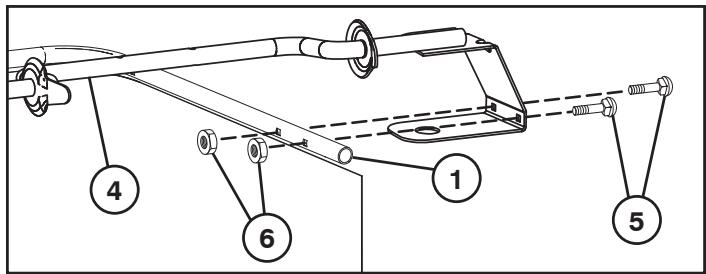
GB STEERING WHEEL
• Mount extension shaft (1).
- Mount the main shaft cover. Make sure that the guide tabs in the cover fit the cover in respective holes.
- Remove steering wheel adapter from steering wheel and slide adapter onto steering shaft. Check that the front wheels are aligned forward and place the wheel on the hub.
- Assemble large flat washer, lockwasher and 5/16 hex bolt. Tighten securely.
- Snap insert into center of steering wheel.
1. EXTENSION SHAFT


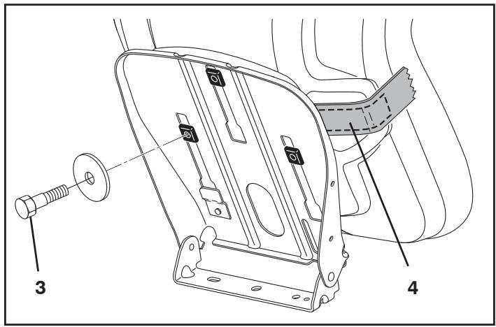
INSTALL SEAT
Remove the hardware securing seat to the cardboard packing and set the hardware aside for assembly of seat to tractor.
Remove the cardboard packing and discard.
NOTE: Check that the flex is correctly connected to the safety switch (1) on the seat holder.
Place seat on seat pan so pads are positioned over large slotted hole in pan (2).
Push down on seat to engage pads in slots and pull seat towards rear of tractor.
Tighten the bolt securely (3).
ADJUST SEAT
Lift up adjustment lever (4) and slide seat until a comfortable position is reached which allows you to press clutch/brake pedal all the way down. Release lever to lock seat in position.

SITZ MONTIEREN
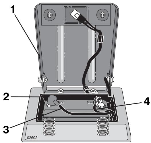
- Seat pan
- Terminal Cover
- Cable (+)
- Cable (-)
A. Front of tractor
- Fender
- Battery terminal
- Battery

- Asiento
- Cubierta Terminal
- Cable (+)
- Cable (-)
NOTE: If battery is put into service after month and year indicated on label, charge battery for minimum of one hour at 6-10 amps.

WARNING: Before installing battery remove metal bracelets, wrist watch bands, rings, etc. from your person. Touching these items to battery could result in burns.

EINBAU DER BATTERIE
WARNING: Positive terminal must be connected first to prevent sparks from accidental grounding.
Remove terminal caps and discard. Connect the red cable to + and then the black earth cable to -. Screw tight the cables. Grease the battery poles with vaseline to prevent corrosion.


GB BAGGER PARTS
DE TEILE DES GRAS-AUFFANGBEHÄLTERS
FR PIÈCES DE RECHANGE DU RAMASSE-HERBE
ES PIEZAS DE LA ENSACADORA
IT PARTI DEL SACCO DI TELA
NL ONDERDELEN OPVANGBAK
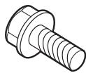
(8) 1/4 × 20 × 1.25"
Carriage Bolts
Karosserieschrauben
Boulons de carrosserie
Tornillos de cabeza redonda
Bulloni a testa tonda
Slotbouten
(6) 1/4 × 20 × 1.15
Shoulder Bolts
Ansatzschrauben
Boulons à épaulement
Pernos de tope
Bulloni di spallamento
Borstbouten
(3) 1/4 × 20 × 0.75"
Bolt
Schraube
Boulon
Perno
Bullone
Bout
(10) 1/4 × 20
Flange Lock Nuts
Flanschkontermuttern
Écrous frein
Tuerca de presión con brida
Dadi flangiati
Flensborgmoeren
(5) 1/4 × 20
Square Nuts
Vierkantmuttern
Écrous carrés
Tuercas cuadradas
Dadi quadrati
Vierkantmoeren
(2) 1/4 × 1.15"
"Bosscrew" (Gold)
(Thread for plastic)
"Bosscrew" (Gold)
(Gewinde für Kunststoff)
"Bosscrew" (Dorée)
(Filet pour plastique)
“Bosscrew” (Dorado)
(Rosca para plástico)
"Bosscrew" (Oro)
(Filettatura per plastica)
"Bosscrew" (Goud)
(Draad voor kunststof)
(2) 1/4 × 15 × 0.5"
Screw
(Thread for plastic)
Schraube
(Gewinde für Kunststoff)
Vis
(Filet pour plastique)
Tornillo
(Rosca para plástico)
Vite
(Filettatura per plastica)
Schroef
(Draad voor kunststof)
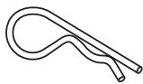
(1) Retainer Spring Clip
(1) Federklammer-Sicherung
(1) Attache à ressort
(1) Abrazadera de arandela de retención
(1) Clip di fissaggio
(1) Sluitveerklem
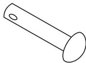
(1) Clevis Pin
(1) Gabelstift
(1) Axe de chape
(1) Pasador de horquilla
(1) Perno
(1) Vorkbout
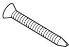
(2) #8 × 1.25
Flat Head Screw
Flachkopfschraube
Vis à tête plate
Tornillo de cabeza plana
Vite a testa piatta
Platkopschroef

(2) Push Nuts
(2) Druckmuttern
(2) Écrous capuchon
(2) Tuercas de empuje
(2) Dadi in gabbia
(2) Drukmoeren

TO ASSEMBLE BAGGER

- Feed top bagger frame tube (1) through loop (2) at the top of bagger fabric (leave loop segments on the ends loose).
- First, align two holes as shown on side of bagger frame upper weldment (4) with corresponding holes in top bagger frame tube (1).
- Install two 1/4"- 20 x 1.25 carriage bolts (5) and secure with two 1/4" nuts (6).
- Align two holes on opposite of bagger frame upper weldment (4) with corresponding holes in top bagger frame tube (1).
- Install two 1/4"- 20 x 1.25 carriage bolts (5) and secure with two 1/4" nuts (6).
- Install two more carriage bolts (7) rearward on sides of top bagger frame tube, hand tightening nuts (8).
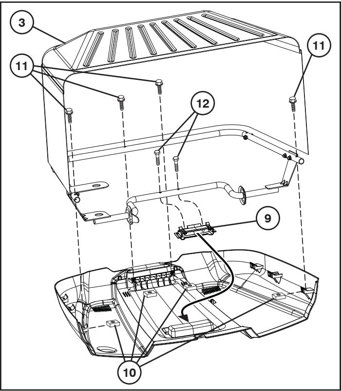
- Lay bagger cover upside-down (leave protective covering intact).
- Slide bagger handle insert (9) into depression on inside of bagger cover. Make sure the two tabs at the top lock into place with the bagger cover. Teeth at the bottom of the bagger handle insert should slide into place in between the teeth on the bagger cover.
- Slide two square nuts (10) into the two square slots at the front of the bagger cover and two square nuts into the two square slots (one slot on each side) at the rear handle of the bagger cover.
- Turn bagger assembly (3) upside-down, lining up holes in the frame to holes in the bagger cover, making sure frame upper weldment tubing is seated in plastic cradle in the bagger handle insert (9).
- Install four 1/4" hex bolts (11) (1/4-20 UNC x 1.15) in holes with four square nuts (10) and tighten until seated.
- Install two 1/4" screws (12) (1/4-20 UNC x 1.15 gold) in holes at center of frame upper weldment.
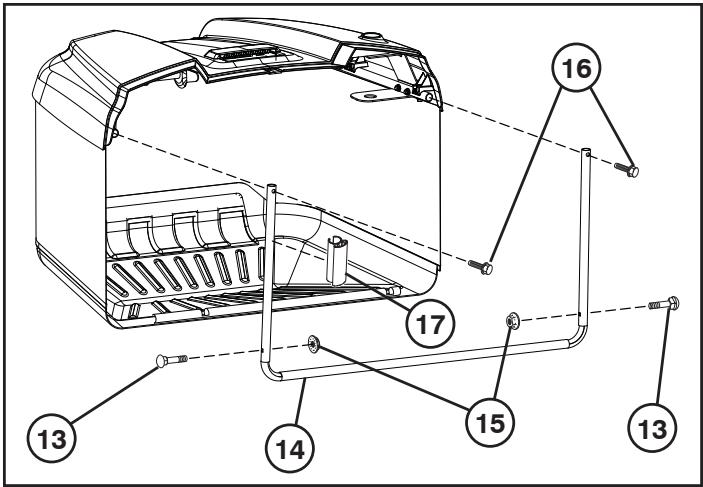
• Turn assembly right-side up.
- Install two 1\4" carriage bolts (13) at bottom of front bagger frame (14), hand tightening lock nuts (15).
- Feed front bagger frame (14) up through fabric loops at front of bagger.
- Snap bottom of front bagger frame (14) into snap feature at front of bagger bottom.
- Slide bagger fabric loop segments at the ends of bag onto top bagger frame tubing.
- Slide two 1\4" hex bolts (16) through holes at top of the front bagger frame and thread into nuts inside the tubing of top bagger frame.
- Slide plastic clip (17) down into bagger fabric loop on right side and snap to front bagger frame (14) 101 mm (4 inches) from top of front bagger frame tube.
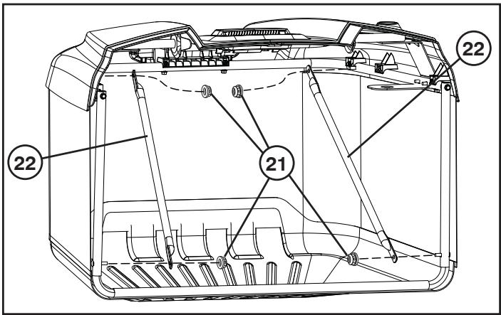
- Uninstall lock nuts (21) at rear of top bagger frame and at bottom of front bagger frame and attach cross braces (22) on each side.
• Reinstall lock nuts (21) and tighten until fully seated.
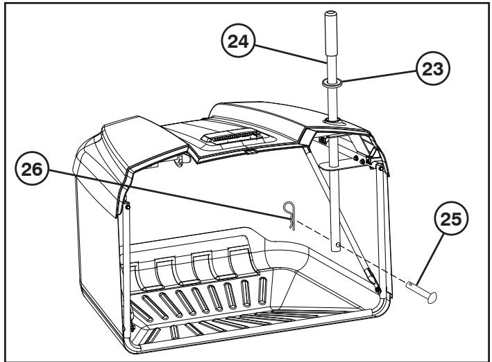
- Slide rubber seal (23) to top of metal bagger handle (24).
- Slide bagger handle (24) down through bagger cover and frame upper weldment holes.
- Slide clevis pin (25) through hole at bottom of bagger handle and slide retainer spring (26) into hole at the end of the clevis pin until it locks into place
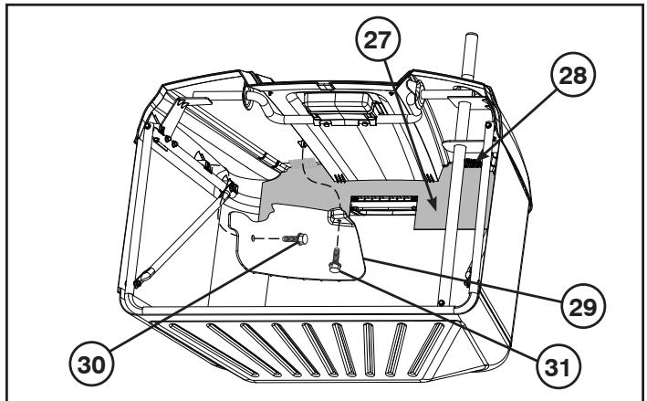
- Push plastic closeout (27) back so that it snaps into place behind retaining ribs (28).
- Line up holes in grass deflector (29) with bosses in bagger cover.
- First install 1/4" hex bolt (30) (1/4"-15 x 1/2") into the side as shown.
- Then install 1/4" hex bolt (31) (1/4"-15 x 1/2") into the top as shown.
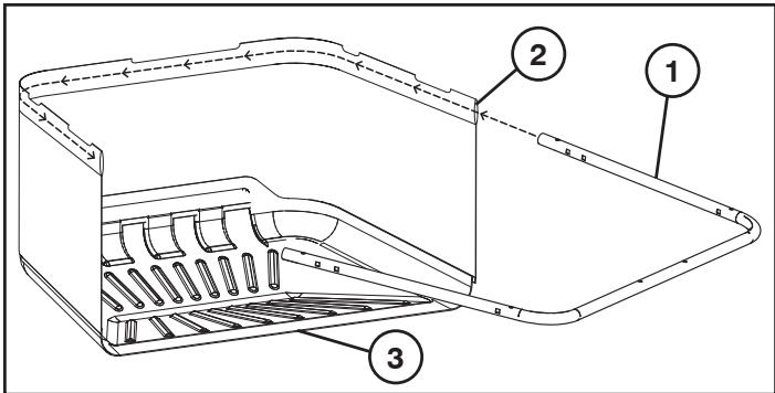
GB TO INSTALL BAGGER FULL LEVER/PADDLE
- Before installation, tractor engine must be shut off and parking brake engaged.
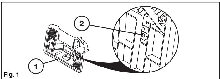
- Standing behind the tractor with the bagger removed from the backplate (1), identify the bag full switch (2) area. (See Fig 1)
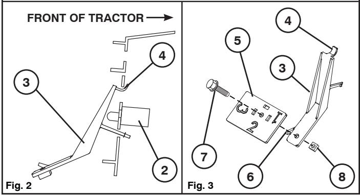
• Take bagger full lever (3) and insert tab(4) into upper slot and rotate until lever (3) snaps into position (See Figs. 2 and 3)
- For the heaviest/wet grasses, do not attach paddle (5).
- For lighter grasses use the paddle (5) on setting "1", "2", or "3" ("3" being for the lightest or dry grass).
- Choose your setting and rotate the bagger paddle (5) so that the desired number (setting) faces you.
- Place paddle (5) on lever (3) so that tab (6) at the bottom of the bagger full lever (3) goes through appropriate rectangular slot and make sure holes in bagger full lever (3) and paddle (5) line up.
- Feed screw (7) through bagger full paddle (5) and lever (3) holes and fasten using nut (8) (See Fig. 3)
- Setting may be changed by loosening fasteners (7 and 8), removing/rotating paddle (5), and tightening again.
GB TO INSTALL BAGGER COMPONENT TO TRACTOR
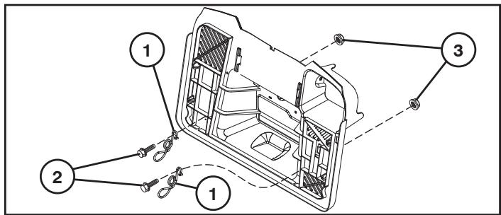
- Before installation, tractor engine must be shut off and parking brake engaged.
• Install latch springs (1) in mounting holes on back plate.
- Insert hex bolt (2) through each latch spring hole and corresponding hole in back plate.
- Fasten lock nut (3) to bolt on the other side of back plate.
GB TO INSTALL BAGGER COVER PANEL
- Install bagger cover panel (1) by angling plastic posts at front of cover panel (1) into corresponding slots at the front of the bagger top.
- Swing back end of cover panel (1) down until it rests on bagger cover.
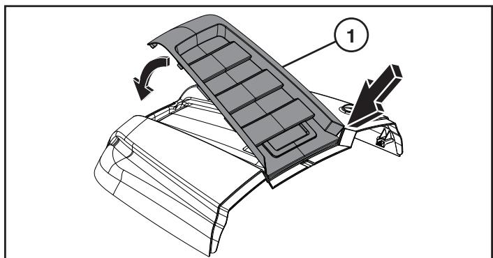
- Slide whole bagger cover panel (1) rearwards so that teeth under the opening in the cover panel slide into the teeth in the handle portion of the bagger cover.
- Apply push nuts (2) to plastic posts to secure cover panel (1) in the front.
- Secure rear side of cover panel (1) to bagger top, and fasten by threading two screws (3) up through rear bagger top handle into the cover panel (1).
DE MONTAGE DER GRASFANGBOX
FR POUR ASSEMBLER LE COLLECTEUR

ES PARA MONTAR EL CONTENEDOR

IT PER MONTARE IL CESTO DI RACCOLTA
NL DE GRASCONTAINER MONTEREN
-
Functional description. 3. Funktionsbeschreibung.
-
Description du fonctionnement.
-
Descripción del funcionamiento. 3. Funzionamento.
-
Beschrijving van functies
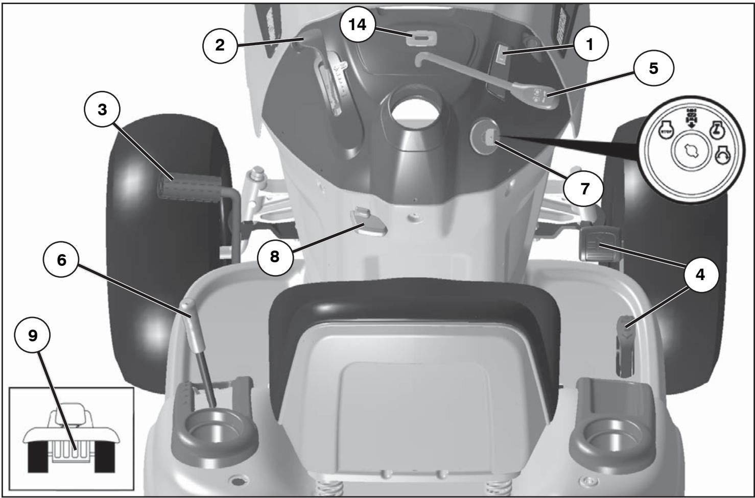

Positioning of controls
- Light switch.
- Throttle control
- Brake and clutch pedal
- Forward/Reverse Drive Pedal.
- Connection/disconnection of the cutting unit
- Quick lifting/lowering of the cutting unit
- Ignition lock
- Parking Brake
- Free-wheel control lever.
- Service Reminder/Hourmeter

natural_image
Isometric line drawing of a 3D object with a handle and circular symbol, no text or labels present
GB 1. Light switch
DE 1. Lichtschalter
FR 1. Interrupteur des phares
ES 1. Interruptor de alumbrado
IT 1. Interruttore luci
NL 1. Schakelaar verlichting
GB 2. Throttle and choke control
The accelerator control regulates the motor speed and also the speed of the blades. If the lever is in its forward position the choke function is connected. If the lever is in its reverse position the motor is in neutral. Full speed lies between these two positions.
natural_image
Technical line drawing of a mechanical component with no visible text or symbols
GB 3. Clutch/Brake Pedal
Used for declutching and braking the tractor and starting the engine.
The direction and speed of movement is controlled by the forward and reverse drive pedals.
natural_image
Close-up of a mechanical component with labeled parts (no readable text or symbols)
natural_image
Interior view of a car dashboard with a close-up of the intake manifold (no text or symbols visible)
GB 5. Connection/disconnection of the cutting unit
Move the lever forward to connect the drive to the cutting unit, whereby the drive belt is tensioned and the blades begin to rotate. If the lever is moved backwards the drive will be disconnected and the rotation of the blades slowed down by the action of the brake shoes on the pulley. If the bagger is not fully closed, blades will not be engaged when lever is moved forward and the engine will shut off. If the bagger becomes disengaged during cutting, the engine will shut off.
natural_image
Close-up of a mechanical assembly with a tool inserted, showing internal components and mounting brackets (no visible text or symbols)

6. Quick lifting/lowering of the cutting unit
Pull the lever backwards to quickly lift the cutting unit when passing over irregularities in the lawn, etc. During transportation the cutting unit shall be in the highest position. Pull the lever back until it locks.

OFF

ROS ON

ON
START
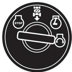
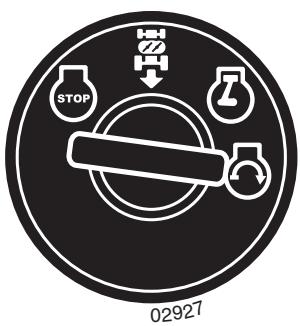
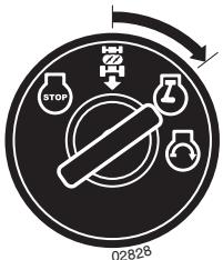
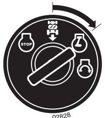
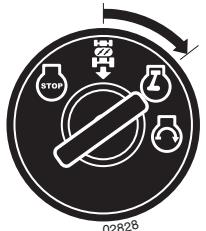
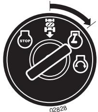
GB 7. Ignition Lock
There are four different positions for the ignition key:
OFF All electric current broken.
ROS ON Reverse Operation System (ROS) connected
ON Electric current connected.
START Start motor connected.
Reverse Operation System (ROS) - Allows operation of mower deck or other powered attachment while in reverse (See section 5 - "Driving").
WARNING!
Never leave the key in the ignition lock when leaving the machine on its own.
DE 7. Zündschloß
natural_image
Mechanical assembly diagram showing a tool inserted into a sink with arrows indicating motion (no text or symbols present)

8. Parking brake
Connect the parking brake in the following way:
- Press down the brake pedal to bottom position.
- Move the parking brake lever upwards and hold in this position.
- Release the brake pedal.
To release the parking brake all that is necessary is to push down the brake pedal.

8. Feststellbremse

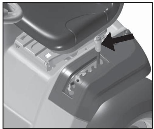
9. Free-wheel Control Lever
To tow or move the tractor without the aid of the engine, the free-wheel control knob must be pulled out and locked in position.

natural_image
Simple line drawing of a rectangular object with a vertical bar and a label '03013' below (no text or symbols on the object itself)

14. Service Reminder/Hourmeter
Indicates when service is required for the engine and mower.

The engine should be run of pure (not oil mixed) unleaded petrol. Do not fill beyond the lower edge of the filling hole. Do not fill over max level.
WARNING!
Petrol is highly inflammable. Proceed with care and fill up with petrol outdoors. Do not smoke when filling with petrol or fill up when the engine is warm. Do not overfill the tank since the petrol can expand and overflow. Make sure that the petrol cap is securely tightened after filling. Store petrol in a cool place in an appropriate container for engine fuel. Check the petrol tank and pipes.
DE Tanken
The combined oil refilling cap and the oil stick is accessible when the bonnet is lifted forwards. The oil level in the engine should be checked before each run. Make sure that the tractor is horizontal. Unscrew the oil stick and wipe clean. Replace the oil stick and screw tight. Remove again and check the level.
DE Ölstand
GB The oil level should lie between the two markings on the oil stick. If more oil is needed add SAE 30 oil to the "FULL" marking. SAE 5W-30 oil should be used during the winter (below freezing point).
natural_image
Circular target diagram with concentric rings and a pointer, no text or symbols present
GB Tire air pressure
Check the tire pressure regularly. The pressure in the front tire should be 1 bar (14 PSI) and 0.8 bar (12 PSI) in the back tires.
DE Reifendruck
natural_image
Medical implant device with mechanical components and a tool inserted (no visible text or symbols)
GB Starting of motor
Sit on seat in operating position, depress brake pedal and set parking brake. Make sure that the cutting unit is in the transport position (top position) and that the lever for connection/disconnection of the cutting unit is in the disconnection position.
natural_image
Illustration of a medical or laboratory setup with a pen, mouse, and rodent (no text or symbols)
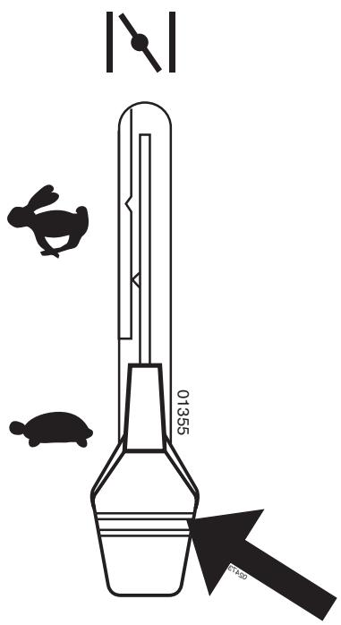
GB Cold motor: Push the gas control up to end positon choke (N).
natural_image
Simple line drawing of a bottle with two small icons: a rabbit and a turtle, no text or symbols present.
GB Warm motor: Push the gas control half-way to full gas position "♥".
DE Bei warmem Motor: Gashebel in die Vollgasstellung "schieben.
(FR) Si le moteur est chaud: pousser la commande des gaz à mi-distance de sa position d'accélération maximale. "♥".
ES Moter caliente: Empuje el acelerador hasta la mitad de su recorrido hacia la posición de plenos gases "♥".
IT Motore caldo: Portare il comando del gas sul massimo "♥".
NL Bij een warme motor: Schuif de gashendel halverwege naar de volgaspositie "♥".
GB Let the ignition key return to the "ON" position when the engine has started Push the gas control to the required speed. For cutting: full gas.
GB PURGE TRANSMISSION
To ensure proper operation and performance, it is recommended that the transmission be purged before operating tractor for the first time. This procedure will remove any trapped air inside the transmission which may have developed during shipping of your tractor.
IMPORTANT: SHOULD YOUR TRANSMISSION REQUIRE REMOVAL FOR SERVICE OR REPLACEMENT, IT SHOULD BE PURGED AFTER REIN STALLATION BEFORE OPERATING THE TRACTOR.
- Park tractor on level surface so it will not roll in any direction. Parking brake must be disengaged for the following procedure.
- Disengage transmission by placing freewheel control in freewheeling position.
- Start engine and move throttle control to slow position. Be sure parking brake is not engaged.
- Depress forward drive pedal to full forward position, hold for five (5) seconds and release pedal. Depress reverse drive pedal to full reverse position, hold for five (5) seconds and release pedal. Repeat this procedure three (3) times.
- Stop tractor by turning ignition key to "OFF" position.
- Engage transmission by placing freewheel control in driving position.
- Start engine and move throttle control to slow position.
- Drive tractor forward for approximately five feet then backwards for five feet. Repeat this driving procedure three times.
- Your tractor is now ready for normal operation.
DE ENTLÜFTEN DES GETRIEBES
The machine is equipped with a safety switch which immediately breaks the current to the engine if the driver leaves the seat with engine running and with the connection/disconnection lever in position “connection”.
DE HINWEIS!
natural_image
Interior view of a car seatbelt device showing two key adjustment buttons (up and down) with no visible text or symbols.
natural_image
Close-up of a mechanical component with a black arrow pointing to a specific part (no visible text or symbols)
GB To Move Forward and Backward
The direction and speed of movement is controlled by the forward and reverse drive pedals.
- Start tractor and release parking brake.
- Slowly depress forward or reverse drive pedal to begin movement. Ground speed increases the further down the pedal is depressed.
Cutting
Lower the cutting unit by moving the lift lever forward and connect the cutting unit. Choose a driving speed which suits the terrain and required cutting results.
Engine "ON" (Normal Operating)
GB Reverse Operation System (ROS)
Your tractor is equipped with a Reverse Operation System (ROS). Any attempt by the operator to travel in the reverse direction with the attachment clutch engaged will shut off the engine unless ignition key is placed in the ROS "ON" position.
WARNING! Backing up with the attachment clutch engaged while mowing is strongly discouraged. Turning the ROS "ON", to allow reverse operation with the attachment clutch engaged, should only be done when the operator decides it is necessary to reposition the machine with the attachment engaged. Do not mow in reverse unless absolutely necessary.
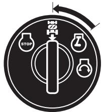
USING THE ROS
- With engine running, turn ignition key counterclockwise to ROS "ON" position.
- Look down and behind before backing.
- Slowly depress reverse drive pedal to begin movement.
- When use of the ROS is no longer needed, turn the ignition key clockwise to engine "ON" position.
- Clear the lawn from stones and other objects which can be thrown away by the blades.
- Localize and mark stones and other fixed objects to avoid collision.
- Begin with a high cutting height and reduce until the required cutting result is obtained.
- The cutting result is best with high engine speed (blades rotate quickly) and low gear (machine goes slowly). If the grass is not too long and thick the drive speed can be increased by selecting a higher gear or reducing the motor speed, without affecting the cutting result.
- The best lawn is achieved if the grass is cut often. Cutting becomes more even and the cut grass is more evenly distributed over the surface. Total time taken is not greater, since higher drive speed can be selected without affecting the cutting results.
- Avoid cutting wet grass. The cutting results will be worse since the wheels will sink into the soft lawn.
- Spray the cutting unit with water underneath after use.
natural_image
Illustration of a person riding a tractor on a slope (no text or symbols)

WARNING!
- Do not drive in terrain at an angle of more than max. 5°. The risk for roll-over backwards is large.
• In steep terrain the risk for tipping is considerable.
- Avoid stopping and starting in sloping terrain.

WARNUNG!
Switching off the engine
Move the attachment clutch control to disengaged position. Move the throttle control between half and full speed (fast) position. Lift up the cutting unit and turn the ignition key to "STOP" position.

Do not leave the ignition key in the machine when not in use to prevent children and other unauthorized persons starting the engine.

WARNUNG!
Before servicing the engine or cutting unit the following shall be carried out:
- Press down the brake pedal and engage the parking brake lever.
- Move connection/disconnection lever to disengaged position.
- Switch off engine.
- Remove the ignition cable from the plug.
DE WARNUNG!
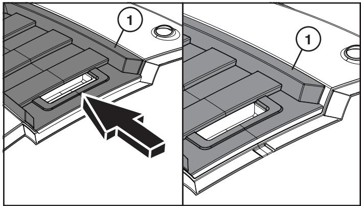
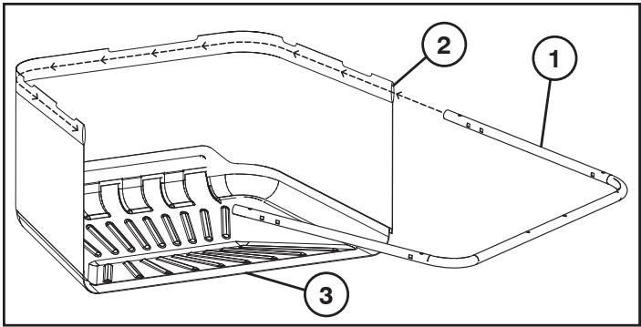
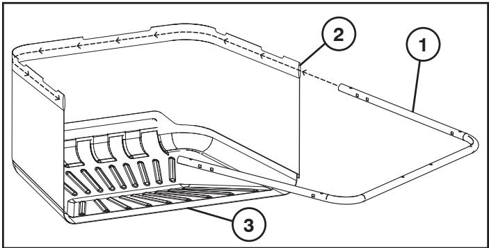
(2) Headlight wire connector
DE (1) Motorhaube
- Raise hood.
• Unsnap headlight wire connector.
- Stand in front of tractor. Grasp hood at sides, tilt forward and lift off of tractor.
- To reinstall, slide hood pivot brackets into slots in frame.
- Reconnect headlight wire connector and close hood.
DE Motorhaube
NOTE: Periodic maintenance should be performed on a regular basis in order to keep your tractor in good running condition.

WARNING: Disconnect spark plug wire to prevent accidental starting before attempting any repair, inspection, or maintenance.
Before each use:
• Check oil, lubricate pivot points as necessary.
- Check to see all bolts, nuts, and cotter pins are in place and secure.
- Check the battery, terminals and vents.
• Recharge slowly at 6 amperes if needed.
- Clean air screen.
- Keep tractor free of dirt and chaff to prevent engine damage or overheating.
- Check brake operation.
Cleaning
Do not use high pressure washer for cleaning. Water can enter engine and transmission and shorten the useful life of the machine.

Wartung

ÖLWECHSEL DURCHFÜHREN
Fill in dates as you complete regular service
| As Needed | Every 8 hours | Every 25 hours | Every. 50 hours | Every. 100 hours | Every 200 hours |
| Change engine oil (without oil filter) | | | ● | | | |
| Change engine oil (with oil filter) | | | | ● | | |
| Lubricate pivot points | | | ● | | | |
| Check brake operation | ● | | | | | |
| Clean air screen | | ● | | | | |
| Clean air filter and pre-cleaner | | ● | | | | |
| Replace air cleaner paper cartridge | | | | | ● | |
| Clean engine cooling fins | | | | ● | | |
| Replace spark plug | | | | | ● | |
| Check tire pressure | ● | | | | | ● |
| Replace fuel filter | | | | | | |
| Clean battery and terminals | | | ● | | | |
| Check muffler | | | | ● | | |

WARTUNGSNACHWEIS
Operator Presence System and Reverse Operation System (ROS)
Be sure operator presence and reverse operation systems are working properly. If your tractor does not function as described, repair the problem immediately.
- The engine should not start unless the brake pedal is fully depressed, and the attachment clutch control is in the disengaged position.
CHECK OPERATOR PRESENCE SYSTEM:
- When the engine is running, any attempt by the operator to leave the seat without first setting the parking brake should shut off the engine.
- When the engine is running and the attachment clutch is engaged, any attempt by the operator to leave the seat should shut off the engine.
- The attachment clutch should never operate unless the operator is in the seat.
- When the engine is running with the ignition switch in the Engine "ON" position and the attachment clutch engaged, any attempt by the operator to shift into reverse should shut off the engine.
- When the engine is running with the ignition switch in the ROS "ON" position and the attachment clutch engaged, any attempt by the operator to shift into reverse should NOT shut off the engine.

PRÜFEN DES RÜCKWÄRTSGANGSYSTEMS (ROS):
VERIFIER LE DISPOSITIF DE SECURITE MARCHE ARRIERE (ROS) :
CONTROLLO DEL SISTEMA PER OPERAZIONI IN RETROMARCIA (ROS):
natural_image
Technical line drawing of a mechanical assembly with a shaft and mounting bracket (no text or symbols)

Blades
For best results mower blades must be kept sharp. Replace bent or damaged blades. Sharpening can be carried out with a file or grinding disc.
NOTE: It is very important that both blades are sharpened equally to avoid imbalance.
BLADE REMOVAL:
- Raise mower to highest position to allow access to blades.
- Remove blade bolt securing blade.
• Install new or resharpened blade with trailing edge up towards deck as shown.
IMPORTANT: To ensure proper assembly, center hole in blade must align with star on mandrel assembly.
- Reassemble blade bolt and tighten securely (45-55 Ft. Lbs. torque).
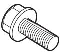
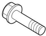
IMPORTANT: Special blade bolt is grade 8 heat treated.

Messerbalken
natural_image
Technical line drawing of a mechanical component with a shaft and mounting bracket (no text or symbols)
ES Cuchillas

To Remove Mower
- Place attachment clutch in "DISENGAGED" position.
• Lower attachment lift lever to its lowest position.
- Remove cable (P) by depressing tab (L)
CAUTION: Belt tension rod is spring loaded. Have a tight grip on rod and release slowly.
- Remove mower belt from clutch pulley (M).
• Dismantle the retainer spring (E) and remove the lever.
• Dismantle the retainer spring (A) and remove the lever.
• Dismantle the retainer spring (D) and remove the lever.
CAUTION: Attachment lift lever is spring loaded. Have a tight grip on rod and release slowly.
- Slide mower out from under right side of tractor.

natural_image
Diagram of a mechanical component with an arrow indicating rotation or motion (no text or symbols)
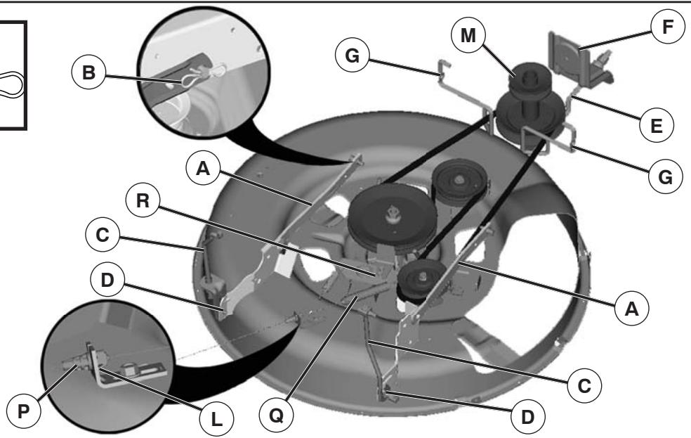
GB Assembly of the cutting unit
- Push in the cutting unit under the machine. The ejector opening should be to the right.
• Assemble in the reverse order to dismantling.
- Park tractor on a level surface. Engage parking brake.
- Lower attachment lift lever to its lowest position.
- Remove any dirt or grass clippings which may have accumulated around mandrels and entire upper deck surface.
-
Remove belt from clutch pulley (M), mandrel pulley (R), and all idler pulleys (V).
MOWER DRIVE BELT INSTALLATION
-
Install belt around both mandrel pulleys (R) and around idler pulleys (V) as shown.
- Install belt onto clutch pulley (M).
IMPORTANT: Check belt for proper routing in all mower pulley grooves.
- Raise attachment lift lever to highest position.
Make sure tires are properly inflated to the PSI shown on tires. If tires are over or under inflated, it may affect the appearance of your lawn and lead you to think the mower is not adjusted properly.
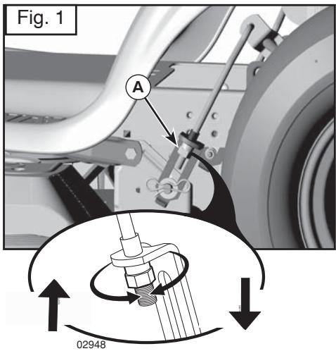
VISUAL SIDE-TO-SIDE ADJUSTMENT
- With all tires properly inflated and if your lawn appears unevenly cut, determine which side of mower is cutting lower.
- With a 3/4" or adjustable wrench, turn lift link adjustment nut (A) to the left to lower the mower, or, to the right to raise the mower (Fig. 1).
NOTE: Each full turn of adjustment nut will change mower height about 3/16".
- Test your adjustment by mowing some uncut grass and visually checking the appearance. Readjust, if necessary, until you are satisfied with the results.
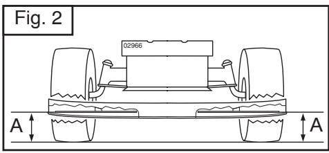
PRECISION SIDE-TO-SIDE ADJUSTMENT
- With all tires properly inflated, park tractor on level ground or driveway.
⚠️ CAUTION: Blade is sharp. Protect your hands with gloves and/or wrap blade with heavy cloth.
- Raise mower to its highest position.
- At both sides of mower, position blade at side and measure the distance (A) from bottom edge of blade to the ground. The distance should be the same on both sides (Fig. 2).
- If adjustment is necessary, see step 2 in Visual Adjustment instructions above.
- Recheck measurements, adjust if necessary until both sides are equal.
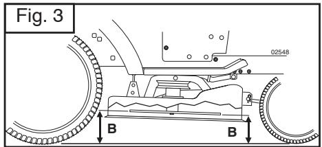
IMPORTANT: Deck must be level side-to-side.
To obtain the best cutting results, the mower blades should be adjusted so the front tip is 1/8" to 3/8" lower than the rear tip when the mower is in its highest position.
⚠️ CAUTION: Blade is sharp. Protect your hands with gloves and/or wrap blade with heavy cloth.
- Raise mower to highest position.
- Position blade so the tip is pointing straight forward. Measure distance (B) to the ground at front and rear tip of the blade (Fig. 3).
- If front tip of blade is not 1/8" to 3/8" lower than the rear tip, go to the front of tractor.
- With an 11/16" or adjustable wrench, loosen jam nut A several turns to clear adjustment nut B.
- With a 3/4" or adjustable wrench, turn front link adjustment nut (B) clockwise (ltighten) to raise the front of mower, or, counterclockwise (loosen) to lower the front mower (Fig. 4).
NOTE: Each full turn of the adjustment nut will change mower height about 1/8".
- Recheck measurements, adjust if necessary until front tip of blade is 1/8" to 3/8" lower than the rear tip.
- Hold adjustment nut in position with wrench and tighten jam nut securely against adjustment nut.
If tractor requires more than five (5) feet to stop at highest speed in highest gear on a level, dry concrete or paved surface, then brake must be serviced.
You may also check brake by:
- Park tractor on a level, dry concrete or paved surface, depress brake pedal all the way down and engage parking brake.
- Disengage transmission by placing freewheel control in freewheeling position.
The rear wheels must lock and skid when you try to manually push the tractor forward. If the rear wheels rotate, then the brake needs to be serviced. Contact a qualified service center.
GB Replacement of drive belt
Dismantle the cutting unit as described previously
Engage the parking brake and work off the belt upwards from the pulley (1), the clutch pulley (2) and the engine's drive wheel (3). Work off the belt upwards from the pulley at the rear axle (4).
GB Assemble in the reverse order to dismantling. Check that the belt lies inside all the belt guides. Use original belts only when replacing!
The fan and cooling fins of transmission should be kept clean to assure proper cooling.
Do not attempt to clean fan or transmission while engine is running or while the transmission is hot.
- Inspect cooling fan to be sure fan blades are intact and clean.
- Inspect cooling fins for dirt, grass clippings and other materials.
TRANSAXLE PUMP FLUID
The transaxle was sealed at the factory and fluid maintenance is not required. Should the transaxle ever leak or require servicing, contact your nearest authorized service center/department.

TRANSACHSEN-KÜHLUNG
Service reminder shows the total number of hours the engine has run and flashes to indicate that the engine or mower needs servicing. When service is required, the service reminder will flash for two hours. To service engine and mower, see the Maintenance section of this manual.
NOTE: Service reminder runs when the ignition key is in any position but “STOP”. For accurate reading, be sure key remains in the “STOP” position when engine is not running.
DE SERVICE REMINDER/STUNDENZÄHLER
Your tractor's deck is equipped with a washout port on its surface as part of its deck wash system. It should be utilized after each use.
- Drive the tractor to a level, clear spot on your lawn, near enough to a water spigot for your garden hose to reach.
IMPORTANT : Make certain the tractor's discharge chute is directed AWAY from your house, garage, parked cars, etc. Remove bagger chute or mulch cover if attached.
- Make sure the PTO (Blade Engage) is not engaged, set the parking brake, and stop the engine.
- Thread the nozzle adapter (A) (packaged with your tractor's Operator's Manual) onto the end of your garden hose (B).
- Pull back the lock collar of the nozzle adapter and push the adapter onto the deck washout port at the left end of the mower deck (C). Release the lock collar to lock the adapter on the nozzle.
IMPORTANT : Tug hose ensuring connection is secure.
- Turn the water on.
- While sitting in the operator's position on the tractor, re-start the engine and place the throttle lever in the Fast "💡" position.
IMPORTANT: Recheck the area making certain the area is clear.
- Move the tractor's PTO (Blade Engage) to the ON position. Remain in the operator's position with the cutting deck engaged until the deck is cleaned.
- Move the tractor's PTO (Blade Engage) to the OFF position. Turn the ignition key to the STOP position to turn the tractor's engine off. Turn the water off.
- Pull back the lock collar of the nozzle adapter to disconnect the adapter from the nozzle washout port.
- Move the tractor to a dry area, preferably a concrete or paved area. Engage the mower deck PTO to remove excess water and to help dry before putting the tractor away.

WARNING: A broken or missing washout fitting could expose you or others to thrown objects from contact with the blade.
- Replace broken or missing washout fitting immediately, prior to using mower again.
- Plug any holes in mower with bolts and locknuts.

GB Engine will not start
- No fuel in fuel tank.
- Plug defective.
- Plug connection defective.
- Dirt in carburetor or fuel pipe.
Start motor will not turn engine
- Battery flat.
- Poor contact between cable and battery pole.
- Connection/disconnection level in wrong position.
- Main fuse defective.
- Ignition lock defective.
- Safety contact for clutch/brake pedal defective.
- Clutch/brake pedal not pushed down.
Engine runs unevenly
- Gear too high.
- Plug defective.
- Carburetor incorrectly set.
- Air filter blocked.
- Fuel tank ventilation blocked.
- Ignition setting defective.
- Dirt in fuel pipe.
Engine feels weak
- Air filter blocked.
- Plug defective.
- Dirt in carburetor or fuel pipe.
- Carburetor incorrectly set.
Engine overheats
- Engine overloaded.
- Air inlet or cooling fins blocked.
- Fan damaged.
- Too little or no oil in engine.
- Ignition setting defective.
- Plug defective.
Battery does not charge
- Fuse defective.
- One or several cells defective.
- Poor contact between battery poles and cables.
Lighting does not function
- Bulbs defective.
- Switch defective.
- Short-circuit in cable.
The machine vibrates
- Blades loose.
- Engine loose.
- Unbalance in one or both blades resulting from damage or poor balancing after sharpening.
Uneven cutting results
- Blades blunt.
- Cutting unit skew.
- Long or wet grass.
- Grass stuck under cover.
- Different air pressures in tires on left and right side.
- Gear too high.
- Drive belt slipping.
GB The following steps should be taken when mowing season is over:
- Clean the entire machine, especially underneath the cutting unit cover. Do not use high pressure washer for cleaning. Water can enter engine and transmission and shorten the useful life of the machine.
- Touch up all chipped paint surfaces in order to avoid corrosion.
- Change engine oil.
- Drain the fuel tank. Start the engine and allow it to run until it is out of fuel.
- Remove the spark plug and pour one table spoon of engine oil into the cylinder. Pull the engine over in order to distribute the oil. Return the spark plug.
- Remove the battery. Recharge and store it in a cool, dry place. Protect the battery from low temperatures.
- The machine should be stored indoors in a dry, dust-free place.
WARNING!
Never use gasoline when cleaning. Use degreasing detergent and warm water instead.
Service
When ordering, we need the following information:
Date of purchase, model, type and serial number of the mower. Always use original spare parts. Contact your local dealer of distributor for warranty service and repairs.