
FS 305 - Chain saw HUSQVARNA - Free user manual and instructions
Find the device manual for free FS 305 HUSQVARNA in PDF.

| Product Type | Floor saw |
| Brand | HUSQVARNA |
| Model | FS 305 |
| Dimensions (L x W x H) | 860 x 505 x 990 mm |
| Weight (empty) | 48 to 52 kg |
| Max. cutting depth | 120 mm |
| Max. blade diameter | 350 mm |
| Blade bore | 25.4 mm |
| Spindle speed | 2450 to 2680 rpm |
| Fuel | Petrol engine (Honda GX160 or Robin EY20) |
| Tank capacity | 17 L |
| Sound power level | 108 dB (Honda) / 102 dB (Robin) |
| Sound pressure level | 84 dB (Honda) / 88 dB (Robin) |
| Vibration level | 1.3 m/s² |
| Blade type | Diamond blade for wet cutting |
| Use | Wet cutting (concrete, asphalt) |
| Maintenance | Check engine oil, clean air filter, lubricate |
| Safety | Mandatory protective guard, emergency engine stop, wear PPE |
| Repairability | Genuine spare parts, repair by professional |
| Compliance | European Directive (CE) |
Frequently Asked Questions - FS 305 HUSQVARNA
User questions about FS 305 HUSQVARNA
0 question about this device. Answer the ones you know or ask your own.
Ask a new question about this device
Download the instructions for your Chain saw in PDF format for free! Find your manual FS 305 - HUSQVARNA and take your electronic device back in hand. On this page are published all the documents necessary for the use of your device. FS 305 by HUSQVARNA.
USER MANUAL FS 305 HUSQVARNA
natural_image
Icon of an open book enclosed in a circle (no text or symbols)DECLARATION OF CONFORMITY WITH EUROPEAN DIRECTIVES
HUSQVARNA CONSTRUCTION PRODUCTS, 433 81 Gothenburg, Sweden, herewith declares that the machine FS305, FS309 conforms to the DIRECTIVES :
• "MACHINES" modified (89/392/CEE)
• "LOW VOLTAGE" modified (73/23/CEE)
• "EMC" (89/336/CEE)
• "NOISE" (2000/14/CEE)
- "WASTE ELECTRICAL AND ELECTRNIC EQUIPEMENT (WEEE)" (2002/96/EC)
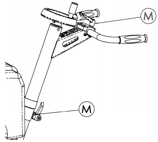
FIG. 2 ABB. 2
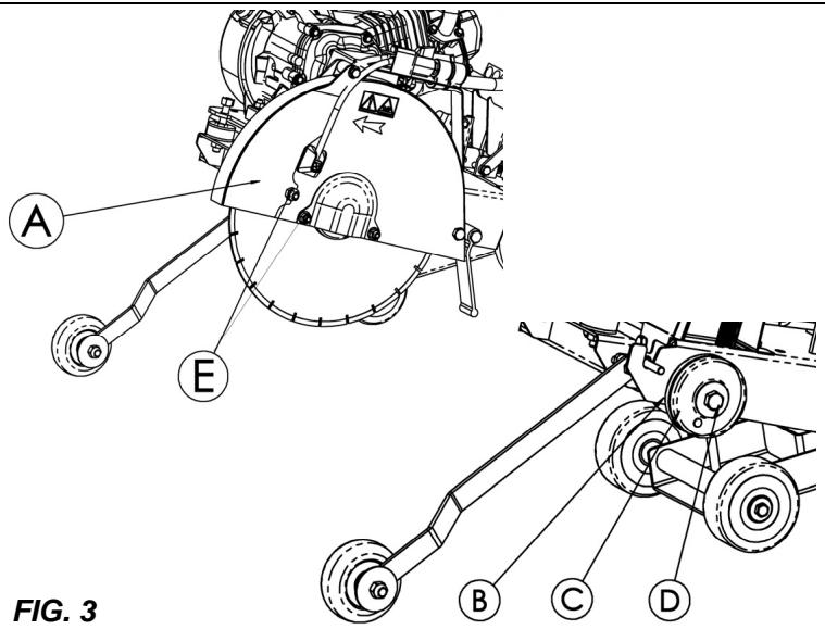
FIG. 3 ABB. 3
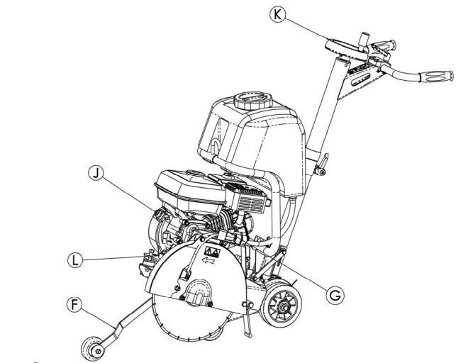
FIG. 4 ABB. 4
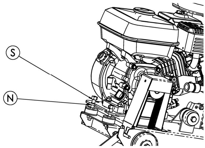
FIG. 5 ABB. 5
Explanation of the symbols
Use of pictograms on the machines (in color) and in the manual indicate safety warnings

WATCH OUT! DANGER! General danger signal.

REQUIREMENT. The following must always be used with the machine:
• certified safety helmet
• certified ear protection
- certified safety goggles or certified eyeshade.

Read manual.

Carefully READ and assimilate the user's manual before operating the machine.

WARNING. Triangle and black marking on yellow background. Danger if instructions are ignored. Risk of injury to user or third party. Risk of damage to machine or tool.
PROHIBITED. Red circle with or without diagonal bar. Use or presence forbidden.

INFORMATION or specific instructions on how to use or check the machine.

This machine complies with the EC directive in force.

STOP symbol.

Safety goggles or eyeshade must be worn.

Loud noise in environment as defined by European Community directive.
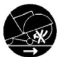
Disk rotation must stop when moving the machine at the work site.

Disk must be removed during slinging, loading, unloading and transport at the worksite.

This symbol indicates that the machine is in conformance with the applicable European directive.

MANDATORY

INDICATION INFORMATION INSTRUCTION

WARNING

PROHIBITION
These signs give advice concerning your safety
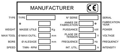
Instruction plate
SPECIAL INSTRUCTIONS
The disc cutter is designed to provide safe and reliable service in operating conditions corresponding with the instructions, but it can present dangers for the user and risks of damage, consequently regular on site inspection is necessary to ensure :
- Perfect technical condition (use for the purpose for which it is intended and taking into account any risks, and correction of any malfunction detrimental to safety).
- Use a diamond disk for cutting with water (sawing new or old concrete, tarmac or asphalt). No other type of disk is allowed (abrasive, saw, etc...).
- Competent staff (qualifications, age, training) who have read and understood the manual in detail before starting work: any electrical, mechanical or other problem should be investigated by a qualified maintenance engineer (electrician, maintenance manager, approved dealer, etc...).
- That the warnings and instructions marked on the machine are followed (adequate personal protection, correct use, general safety instructions, etc).
- That no modification, transformation or addition is detrimental to safety and that it is carried out without prior authorization from the manufacturer.
- Respect of the maintenance intervals and periodical checks recommended.
- That only genuine spare parts are used for repairs.

FAILURE TO COMPLY WITH THESE WARNINGS COULD RESULT IN DEATH OR SERIOUS BODILY INJURY.

DO
DO carefully read and understand all the instructions before operating the saw.
DO always keep all guards in place.
DO aways wear safety approved hearing, eye, head and respiratory protection.
DO keep all parts of your body away from the blade and all other moving parts.
DO know how to stop the saw quickly in case of an emergency.
DO shut off the engine and allow it to cool before refueling.
DO inspect the blade, flanges and shafts for damage before installing the blade.
DO use only blades marked with a maximum operating speed greater than the blade shaft speed.
DO use caution and follow the instructions when loading and unloading the saw.

DO NOT
DO NOT allow other persons to be near the saw when starting, refueling or when cutting.
DO NOT operate gasoline engines in an enclosed area unless it is properly vented.
DO NOT use damaged equipment or blades.
DO NOT operate the saw in areas of combustible material. Sparks from the saw could cause a fire or an explosion.
DO NOT allow blade exposure from the guard to be over 180 degrees.
DO NOT leave the saw unattended with the motor running.
DO NOT operate the saw while under the influence of drugs or alcohol.
1
Use
- Utilisation : sawing with sprinkling of fresh, old or coated (asphalt) concrete.
- Tools : Water-cooled diamond-impregnated discs - ∅ 350 mm - bore 25.4 mm.
(Details from your usual supplier).
2
Technical specifications
- Depth of cut : ∅ 350: 120 mm
- Nominal weight (unladen) : 48 to 52 kg (depending on version)
• Service weight : 52 to 70 kg (including tank) - Dimensions (LxWxH) :
- 860 x 505 x 990 mm
• Speed of spindle rotation :
2450-2680 rpm
(depending on version)
| MODEL | LEVELLwa (dB) | LEVELLpa (dB) | LEVELG ENV |
| EN ISO 3744 | EN ISO 4871 | 25349 | |
| HONDAGX160 | 108 | 84 | 1.3 |
| ROBINEY20 | 102 | 88 | 1.3 |
3
Description of the machine [FIG. 1]
- Handle
- Motor stop
- Lowering handwheel
- Graduated scale
- Engine
- Engine oil drain
- Front guide
- Belt cover
- Disk casing
- Service spanner
- Water intake tap
- Tank (17 litres)
4
Handling - Transport

Switch off the disk prior to moving the machine on jobsite.

Remove the disk prior to hoisting, loading, unloading and transporting the machine on jobsite.
Height of adjustable handlebars (unscrew the lever (M)) [SEE FIG. 2].
- The ground-saw only needs pushing to move it into position on the site. It is easy to move on its four wheels, without starting the motor.
- The handwheel (K) locks the machine itself in the high position.
- Light weight, compact, transportable in a vehicle by one person.

Check before starting

Please read the instructions for use prior to operating the machine for the first time.

Motor off.

The working area must be completely cleared, well lit and all safety hazards removed (no water or dangerous objects in the vicinity)


The operator must wear protective clothing appropriate to the work he is doing. We recommend that this includes both eye and ear protection


The use of ear protection is mandatory.

Any persons not involved in the work should leave the working area

Use only blades marked with a maximum operating speed greater than blade shaft speed


Take into account the working conditions from health and safety point of view.
- Model with petrol motor (refer to the motor maintenance manual).
■ Make sure the fuel is topped up.
■ Check the oil level; as the motor often works at an angle, check it frequently in the horizontal position that the oil level is never below the second line on the gauge.
■ To start up, refer to the motor instructions.

Fitting the blade

Motor off
- Place the machine in an high position.
-
Make sure the engine is switched off.
-
Unscrew the nuts (E) from the guard housing [SEE FIG. 3].
- Remove the guard housing (A).
- Fit the diamond impregnated disc.

Note the direction of rotation indicated by an arrow on one side of the disc (direction of rotation shown on the outside of the guard housing).
Check the state of cleanliness of the disc support faces of the adaptor plates (B and C) and of the spindle.
- Firmly tighten the screw (D) with the spanner provided with the machine, holding the disc steady by hand.
- Replace the protective guard (if this is not replaced the casing safety switch will prevent the saw being started).
- Reconnect the water hose (mains with valve or tank).
- Tighten the nut (E).

The holding screw (D) of the disc has a right-hand thread.

Starting up

Always pay extreme care and attention to the preparation of the machine before starting up

Remove all adjustment tools and wrenches from floor and machine

Always keep blade guard in place
- Turn off the water tap (G) (from the mains or from the tank in order to fill it) [SEE FIG. 4].
- Mark out a line on the ground where a cut has to be made.
- Position the machine so that the lowered front guide (F) and the disc are aligned with the line marked out (disc visible on the belt side of the housing).
- Start up the motor : refer to the motor manufacturer's instructions in the service manual.
- Allow the motor to warm up.
- Turn on the water supply tap (G) (from the mains or the water tank).
- Increase the motor speed to full.
- Hold the saw, turn the handwheel (K) and position the disk in contact with the floor.
- Lower to the depth of cut required, and bearing in mind that each graduation of the scale corresponds to a depth of 1cm. Lower slowly to prevent the engine stalling.
- Gently move the machine forward ensuring that the front guide and the disc are always aligned with the line marked out.
Ensure that the water supply is abundant, when cutting wet.

Stopping the machine

Motor off
- Turn the handwheel (K) to free the disk from the groove [SEE FIG. 4]
- No need to lock the saw up by releasing the handwheel (K).
- Turn off the water supply (G).
- Allow the motor to run idle.
- Switch off the motor (refere to the motor maintenance manual).

Emergency stop
Operate the switch (J) in front of the engine.

Incidents during sawing
- There may be several causes responsible for arresting the disc in the sawing groove or stopping the machine:
■ Belt tension.
■ Lack of fuel.
■ Advance or lowering too fast, etc.
- In all case, disengage the disc from the groove and give the machine a complete check-over.

Entrust repairs to authorised dealer only

Maintenance (with the engine stopped)

"Engine Maintenance": refer to the engine maintenance booklet.
• After use, clean the machine.
- Lubrication : apply a moderate amount of bearing lubricant to the nipples in the depth adjustment chassis (depending on the frequency of use).


OIL
- Check the engine oil everyday. Refer to the engine manual for oil change schedule. Use :
■ SAE 10W30 motor oil with API class MS, SD, SE or better for PETROL engines.
■ API class CD or CE for Hatz diesel.

Dispose of the old oil as laid down by the regulations in force.
- To change the oil, remove the disk, lower the saw to the lowest position and then place the tray by the drain outlet (L) [SEE FIG. 4].

Store in a safe place, out of reach of children
Maintain tools carefully
AIR FILTER
- Read engine owners manual for maintenance intervals. For extremely dusty conditions you may have to clean the air filter element 2 to 3 times a day.
- Replace any damaged filters or gaskets.

Store in a safe place out of reach of children.
Remove all adjustment tools and wrenches
Store diamond tool in a safe place so it cannot be bent or damaged.
11 Engine belt tension
It may be necessary after using a few times to retention the belts, without over-tightening them. To do this :
- loosen the 2 nuts (S) fixing the motor to the chassis, without removing them [SEE FIG. 5];
- tighten the tensioning nuts (N), these screws pull the motor up.
- at normal tension, tighten the motor fixing nuts (S).
12 Important advice
- Periodically, tighten the nuts and bolts and particularly after the first few hours of use.
- Check belt tensions, tighten them without overdoing it.
- When garaged, it is recommended the disc be removed and suitably stored.
- Make sure the disc is correctly tightened.
- Make sure the disc supports surfaces, the adaptor plates and the spindle are kept clean.

The manufacturer declines all responsibility for loss or damage resulting from misuse or any modification, alteration or powering that does not conform to the manufacturer's original specifications.

At the work station, the sound pressure level may exceed 85 db (A)
In this case individual protection measures must be taken.

When working in a limited or closed area, make sure that the ventilation is adequate. The exhaust gases contain carbon monoxide (exposure to this toxic gas can cause loss of consciousness and can be fatal).
13 Repairs

We carry out all repairs in the shortest possible time and at the most economical prices (see overleaf for our address).
14 Spare parts
For quick supply of spare parts and to avoid any lost time it is essential to quote the data on the manufacturer's plate fixed to the machine and the part number of the part to be replaced with every order.

flowchart
graph TD
    A["00000000"] --> B["Item number"]
    C["(0)"] --> D["Quantity"]
See exploded view
15 Scrapping

In the event of deterioration and scrapping of the machine, the following items must be disposed of in accordance with the requirements of the legislation in force.
- Main materials :
- Motor : Aluminium (AL), Steel (AC), Copper (CU), Polyamide (PA)
• Machine : Steel sheet (AC), Cast iron (FT) Aluminium (AL)
The instructions for use and spare parts found in this document are for information only and are not binding.
As part of our product quality improvement policy, we reserve the right to make any and all technical modifications without prior notice.
Manutention - Transport

- DECLARATION OF CONFORMITY WITH EUROPEAN DIRECTIVES
- Explanation of the symbols
- SPECIAL INSTRUCTIONS
- DO
- DO NOT
- 1
- Use
- 2
- Technical specifications
- 3
- Description of the machine [FIG. 1]
- 4
- Handling - Transport
- Check before starting
- Motor off.
- Fitting the blade
- Motor off
- Starting up
- Stopping the machine
- Incidents during sawing
- Entrust repairs to authorised dealer only
- Maintenance (with the engine stopped)
- "Engine Maintenance": refer to the engine maintenance booklet.
- OIL
- Dispose of the old oil as laid down by the regulations in force.
- Store in a safe place, out of reach of children
- Maintain tools carefully
- AIR FILTER
- Store in a safe place out of reach of children.
- Engine belt tension
- Important advice
- Repairs
- Spare parts
- Scrapping
- Manutention - Transport
Brand : HUSQVARNA
Model : FS 305
Category : Chain saw