
233 RJ - Chain saw HUSQVARNA - Free user manual and instructions
Find the device manual for free 233 RJ HUSQVARNA in PDF.

| Product Type | Brushcutter / Grass Trimmer |
| Brand | HUSQVARNA |
| Model | 233 RJ |
| Displacement | 29.5 cm³ |
| Max. Power | 1.0 kW / 8000 rpm |
| Idle Speed | 3000 rpm |
| Max. Output Shaft Speed | 10000 rpm |
| Fuel Tank Capacity | 0.75 L |
| Fuel | Unleaded gasoline min 90 octane + 2-stroke oil (ratio 1:50) |
| Spark Plug | NGK CMR7H-10 (gap 0.9-1.0 mm) |
| Weight (without fuel, cutting equipment and safety devices) | 5.5 kg |
| Guaranteed sound power level | 112 dB(A) |
| Approved cutting equipment | Grass blade Ø255 mm (4 teeth or 3 teeth), Tricut plastic knives Ø300 mm, trimming heads T25, T35, S35 |
| Main functions | Weeding, brushcutting, cutting of tall and thick grass |
| Regular maintenance | Clean air filter every 25 h, clean cooling system weekly, check spark plug monthly |
| Mandatory safety equipment | Helmet, ear protectors, safety glasses, gloves, steel-toe boots, resistant clothing |
| Safety distance | Minimum 15 meters around the user |
| Anti-vibration system | Yes, built-in |
| Spare parts | Use exclusively Husqvarna original parts |
| General information | Complies with EC directives (98/37/EC, 2004/108/EC, 2000/14/EC) |
Frequently Asked Questions - 233 RJ HUSQVARNA
User questions about 233 RJ HUSQVARNA
0 question about this device. Answer the ones you know or ask your own.
Ask a new question about this device
Download the instructions for your Chain saw in PDF format for free! Find your manual 233 RJ - HUSQVARNA and take your electronic device back in hand. On this page are published all the documents necessary for the use of your device. 233 RJ by HUSQVARNA.
USER MANUAL 233 RJ HUSQVARNA
natural_image
Simple line drawing of an open book enclosed in a circle (no text or symbols)Please read the operator's manual carefully and make sure you understand the instructions before using the machine.
DE (2-26)
FR (27-51)
NL (52-76)
SE (77-101)
DK (102-126)
FI (127-150)
NO (151-175)
GB (176-200)
Symbole
natural_image
Diagram of a mechanical component with three circular icons below showing gear, star, and triangle symbols (no text or labels)
Was ist was?
natural_image
Line drawing of a helmet and safety goggles (no text or symbols)GEHÖRSCHUTZ
natural_image
Line drawing of glasses and accessories (no text or symbols)HANDSCHUHE
natural_image
Technical line drawing of a mechanical device with a curved arrow indicating rotation (no text or symbols)natural_image
Technical line drawing of a mechanical component with an arrow indicating upward motion (no text or symbols)natural_image
Diagram of a mechanical tool with directional arrows indicating motion or force (no text or symbols)Stoppschalter
natural_image
Line drawing of a mechanical device with a downward arrow indicating force or movement (no text or symbols)natural_image
Line drawing of a propeller blade assembly (no text or symbols)natural_image
Technical line drawing of a mechanical device with no visible text or symbols
natural_image
Three technical line drawings of mechanical components, showing different types of housing or assemblies (no text or symbols present)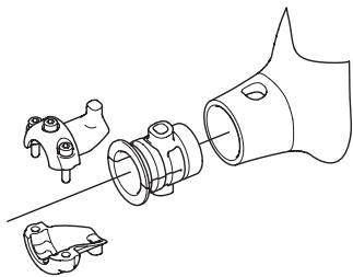
natural_image
Technical line drawing of a mechanical assembly with exploded view (no text or symbols)natural_image
Line drawing of a mechanical device with two circular ports and a handle (no text or symbols)natural_image
Line drawing of a mechanical switch or lever device (no text or symbols)natural_image
Technical line drawing of a mechanical component with an arrow indicating direction (no text or symbols)natural_image
Technical illustration of a mechanical component with a nut and rotating arrow (no text or symbols)natural_image
Three abstract geometric shapes with circular centers and curved surfaces, no text or symbols presentnatural_image
Technical line drawing of a mechanical component and its cross-sectional view (no text or symbols)Grundregeln

natural_image
Three abstract line drawings: a triangular shape, a triangular cutout, and a cylindrical object with curved lines (no text or symbols)natural_image
Diagram of a shield blade with an arrow indicating upward motion (no text or symbols)natural_image
Two diagrams showing a tool interacting with a fish-like shape, one with an arrow indicating direction (no text or symbols)
natural_image
Three technical illustrations of mechanical components: a cylindrical fan, a rectangular box with a circular element, and a spool (no text or symbols present)natural_image
Technical line drawing of a mechanical clamp or clamping device with no visible text or symbolsnatural_image
Technical line drawing of a mechanical clamp or tool assembly (no text or symbols)natural_image
Line drawing of a mechanical clamp or bracket assembly (no text or symbols)
natural_image
Technical line drawing of a mechanical component with cross-sectional views (no text or symbols)
natural_image
Two technical line drawings of a mechanical component with labeled parts (H), showing angular and radial features without any text or symbols.natural_image
Diagram of a coiled cable or hose with labeled components A, B, and C (no text or symbols beyond labels)natural_image
Illustration of a fuel can being poured into a gas cylinder with an oil drop symbol (no text or labels)natural_image
Two abstract line drawings with arrows pointing to a central circular feature, no text or symbols present.natural_image
Simple line drawing of a circular object with a downward arrow pointing to its center (no text or symbols)natural_image
Line drawing of a garment collar with a knob and arrow indicating direction (no text or symbols)natural_image
Simple line drawing of a mechanical component with no text or symbolsStarten und stoppen


natural_image
Technical line drawing of a mechanical component with no visible text or symbolsChoke: Den Chokehebel in Choke-Lage führen.

natural_image
Technical line drawing of a car engine compartment with no visible text or symbolsnatural_image
Illustration of a person in safety gear using a tool on a workbench (no text or symbols)natural_image
Line drawing of a mechanical device with a prohibition symbol overlay (no text or symbols present)Stoppen

natural_image
Technical line drawing of a mechanical component with an arrow indicating direction (no text or symbols)natural_image
Line drawing of a person spraying a shrub outdoors, no text or symbols presentnatural_image
Line drawing of a person in full protective gear holding a tool, with no text or symbols present.natural_image
Illustration of a hand using a tool to lift a pine branch (no text or symbols)natural_image
Simple line drawing of a grassy field with a tool, no text or symbols presentnatural_image
Simple line drawing of a shovel digging grass on a branch (no text or symbols)natural_image
Simple line drawing of a grassy field with a small mechanical component above (no text or symbols)natural_image
Illustration of a hand holding a mechanical lever with rotating components (no text or symbols)natural_image
Technical line drawing of a car engine compartment with no visible text or symbols
natural_image
Technical line drawing of an automotive engine assembly (no text or symbols visible)natural_image
Technical line drawing of a mechanical assembly with internal components and a separate housing (no text or symbols)1 Kraftstofffilter
natural_image
Diagram of a mechanical joint or connector with an arrow indicating direction (no text or symbols present)Zündkerze

Attention: projections et ricochets.
natural_image
Diagram of a mechanical component with three circular icons below (screw, gear, triangle) and a central rotating knob (no text or symbols)
natural_image
Line drawing of a helmet and safety goggles (no text or symbols)PROTÈGE-OREILLES
natural_image
Technical line drawing of a mechanical tool with an arrow indicating rotation (no text or symbols)natural_image
Diagram of a mechanical device with an upward arrow indicating motion or force (no text or symbols present)INSTRUCTIONS GÉNÉRALES DE SÉCURITÉ
natural_image
Diagram of a mechanical device with directional arrows indicating motion or force (no text or symbols)Bouton d'arrêt
natural_image
Technical line drawing of a mechanical component with an arrow indicating direction (no text or symbols)natural_image
Line drawing of a propeller blade assembly (no text or symbols)natural_image
Technical line drawing of a mechanical device with no visible text or symbols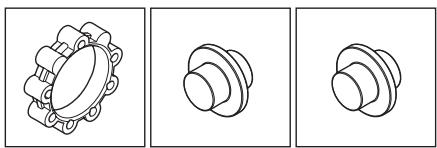
natural_image
Three technical line drawings of mechanical components, showing different mounting or mounting configurations (no text or symbols present)
natural_image
Technical line drawing of a mechanical assembly with exploded view (no text or symbols)natural_image
Line drawing of a mechanical device with two circular buttons and a handle (no text or symbols)natural_image
Line drawing of a mechanical switch or lever device (no text or symbols)natural_image
Technical line drawing of a mechanical component with an arrow indicating direction (no text or symbols)natural_image
Technical line drawing of a mechanical component with a pulley and a nut, showing rotational motion (no text or symbols)natural_image
Three abstract geometric shapes with circular centers and shaded surfaces, no text or symbols present.natural_image
Technical line drawing of a pot and its triangular component (no text or symbols)Règles élémentaires

natural_image
Three abstract line drawings: a triangular shape, a triangular cutout, and a cylindrical object with curved lines (no text or symbols)natural_image
Simple line drawing of a shield with a flag and arrow, no text or symbols presentflowchart
graph TD
    A["Raw food item"] --> B["Heated bowl with spiral lid"]
    B --> C["Recycling into waste bin"]
INSTRUCTIONS GÉNÉRALES DE SÉCURITÉ
natural_image
Two diagrams showing a tool interacting with a blade-like object, one with an arrow indicating direction (no text or symbols)
natural_image
Three technical illustrations of mechanical components: a cylindrical fan, a square plate with a circular hole, and a spool (no text or symbols)natural_image
Technical line drawing of a mechanical clamp or clamping device with no visible text or symbolsnatural_image
Technical line drawing of a mechanical clamp or bracket assembly (no text or symbols)natural_image
Line drawing of a mechanical clamp or clamping device with no text or symbols
natural_image
Technical line drawing of a mechanical assembly with cross-sectional views (no text or symbols)
natural_image
Pure technical line drawing of a mechanical component with no text or symbols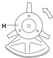
natural_image
Technical line drawing of a mechanical component with labeled part H and directional arrow (no text or symbols beyond basic diagram)natural_image
Illustration of fuel being poured into a fuel can with an oil pump (no text or symbols)natural_image
Two abstract line drawings with arrows pointing to curved and circular shapes, no text or symbols present.natural_image
Simple line drawing of a circular object with a downward arrow pointing to its center (no text or symbols)natural_image
Line drawing of a garment sleeve with a knob and arrow indicating direction (no text or symbols)natural_image
Line drawing of a mechanical component with no visible text or symbolsDémarrage et arrêt


natural_image
Technical line drawing of a mechanical component with an arrow indicating a specific part (no text or symbols present)Starter: Tirer la commande de starter.
natural_image
Technical line drawing of a mechanical component with an inset showing a close-up view of a component (no text or symbols present)natural_image
Illustration of a person in safety gear handling equipment (no text or symbols visible)natural_image
Technical line drawing of a mechanical device with a prohibition symbol (no text or labels)Arrêt
natural_image
Technical line drawing of a mechanical component with an arrow indicating direction (no text or symbols)Méthodes de travail
IMPORTANT!
natural_image
Line drawing of a person in protective gear using a long-handled shrub outdoors (no text or symbols)natural_image
Line drawing of a person in full protective gear holding a tool, no text or symbols presentnatural_image
Illustration of a hand using a manual lever to lift a tree (no text or symbols)natural_image
Simple line drawing of a grassy slope with a tool, no text or symbols presentnatural_image
Simple line drawing of a shovel digging grass with a stick, no text or symbols presentnatural_image
Simple line drawing of a grassy field with a small mechanical component above it (no text or symbols)natural_image
Diagram of a hand holding a pole with a rotating arm, showing motion direction (no text or symbols)natural_image
Technical line drawing of a vehicle engine component with an inset showing a close-up of the internal structure (no text or symbols present)
natural_image
Technical line drawing of an automotive engine assembly (no text or symbols visible)natural_image
Technical line drawing of a mechanical assembly with internal components (no text or symbols)natural_image
Line drawing of a car head assembly with a belt switch and control panel (no text or symbols)natural_image
Diagram of a mechanical joint or connector with an arrow indicating direction (no text or symbols present)Bougie

natural_image
Pure diagram of a mechanical component with three circular icons below (no text or symbols)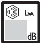
Wat is wat?
natural_image
Line drawing of a helmet and hard hat device (no text or symbols)GEHOORBESCHERMING
natural_image
Line drawing of glasses and accessories (no text or symbols)HANDSCHOENEN
Draag handschoenen indien nodig, b.v. wanneer u de snijuitrusting monteert.
LAARZEN
natural_image
Technical line drawing of a mechanical component with an arrow indicating direction (no text or symbols)natural_image
Diagram of a mechanical component with an upward arrow indicating motion or force (no text or symbols present)natural_image
Diagram of a mechanical lever mechanism with bidirectional arrows indicating motion (no text or symbols)Stopschakelaar
natural_image
Technical line drawing of a mechanical component with a downward arrow indicating motion (no text or symbols)natural_image
Line drawing of a mechanical component with blades and a central knob (no text or symbols)natural_image
Technical line drawing of a mechanical device with no visible text or symbols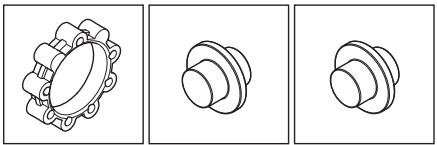
natural_image
Three technical line drawings of mechanical components, showing different types of housing or assemblies (no text or symbols present)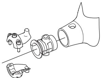
natural_image
Technical line drawing of a mechanical assembly with exploded view (no text or symbols)natural_image
Line drawing of a mechanical device with two circular ports and a handle (no text or symbols)Controleer regelmatig of de geluiddemper vastzit in de machine.
natural_image
Line drawing of a mechanical switch or lever device (no text or symbols)natural_image
Technical line drawing of a mechanical component with an arrow indicating direction (no text or symbols)natural_image
Technical illustration of a mechanical component with a nut and rotating arrow (no text or symbols)natural_image
Three abstract geometric shapes with circular centers and curved surfaces, no text or symbols presentnatural_image
Technical line drawing of a mechanical component and its cross-sectional view (no text or symbols)Basisregels

natural_image
Three abstract line drawings: a star-like shape, a triangular shape, and a coiled spring-like object (no text or symbols)natural_image
Diagram of a shield with a flag and arrow indicating direction (no text or symbols)natural_image
Two diagrams showing a tool interacting with a stylized fish shape, one with an arrow indicating direction (no text or symbols)
natural_image
Three technical illustrations of mechanical components: a cylindrical fan, a rectangular box with a circular dial, and a coiled spring (no text or symbols)natural_image
Technical line drawing of a mechanical clamp or clamping device with no visible text or symbolsnatural_image
Technical line drawing of a mechanical clamp or bracket assembly (no text or symbols)natural_image
Line drawing of a mechanical clamp or clip assembly (no text or symbols)
natural_image
Technical line drawing of two mechanical assembly configurations (no text or symbols)
Monteren van trimmerbeschermkap en trimmerkop
natural_image
Pure technical line drawing of a mechanical component with no text or symbols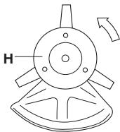
natural_image
Technical line drawing of a mechanical component with labeled H and directional arrow (no text or symbols beyond basic labels)natural_image
Technical line drawing of a coiled cable or hose assembly with labeled components A, B, and C (no text or symbols beyond labels)Brandstofveiligheid
natural_image
Illustration of a fuel pump with a bottle pouring liquid into a flax (no text or symbols)natural_image
Two abstract line drawings with arrows pointing to a central circular feature, no text or symbols present.natural_image
Simple line drawing of a circular object with a downward arrow pointing to its center (no text or symbols)natural_image
Line drawing of a garment collar with a knob and arrow indicating direction (no text or symbols)- Controleer de trimmerkop en de trimmerbeschermkap op beschadigingen en barsten. Vervang de trimmerkop of de trimmerbeschermkap
natural_image
Simple line drawing of a mechanical component with no text or symbolsStarten en stoppen


natural_image
Technical line drawing of a mechanical component with no visible text or symbolsChoke: Zet de choke-hendel in de choke-positie.
natural_image
Technical line drawing of a mechanical component with no visible text or symbolsnatural_image
Illustration of a person in safety gear handling equipment (no text or symbols visible)natural_image
Line drawing of a mechanical device with a prohibition symbol overlay (no text or symbols present)Stoppen

natural_image
Technical line drawing of a mechanical component with a downward arrow indicating force or direction (no text or symbols)natural_image
Line drawing of a person spraying a shrub outdoors, no text or symbols presentnatural_image
Line drawing of a person in full protective suit using a long-handled tool (no text or symbols)natural_image
Illustration of a hand using a tool to lift a pine branch (no text or symbols)natural_image
Simple line drawing of a grassy field with a mounted tool (no text or symbols)natural_image
Simple line drawing of a manual tool cutting grass with a tool, no text or symbols presentnatural_image
Simple line drawing of a grassy field with a small mechanical component above it (no text or symbols)natural_image
Diagram of a hand holding a tool with rotating arm and directional arrows (no text or symbols)natural_image
Technical line drawing of a car engine compartment with no visible text or symbols
natural_image
Technical line drawing of an automotive engine assembly (no text or symbols visible)natural_image
Technical line drawing of a mechanical assembly with internal components (no text or symbols)natural_image
Diagram of a car head assembly with a belt switch and directional control panel (no text or symbols)1 Brandstofffilter
natural_image
Diagram of a mechanical joint or connector with an arrow indicating direction (no text or symbols present)Bougie

Michael Kullberg, Business manager
Symboler
natural_image
Circular icon with a stylized face wearing sunglasses and a helmet, enclosed in a circle (no text or symbols)


natural_image
Diagram of a mechanical component with gear and triangular elements, no text or symbols present

Vad är vad?
natural_image
Line drawing of a helmet and safety goggles (no text or symbols)HÖRSELSKYDD
natural_image
Line drawing of glasses and accessories (no text or symbols)HANDSKAR
natural_image
Technical line drawing of a mechanical component with a curved arrow indicating rotation (no text or symbols)natural_image
Diagram of a mechanical component with an upward arrow indicating motion or force (no text or symbols present)natural_image
Diagram of a mechanical device with directional arrows indicating motion or force (no text or symbols)ALLMÄNNA SÄKERHETSINSTRUKTIONER
Stoppkontakt
natural_image
Line drawing of a mechanical device with a downward arrow indicating motion (no text or symbols)natural_image
Line drawing of a mechanical component with blades and a central knob (no text or symbols)natural_image
Technical line drawing of a mechanical device with no visible text or symbols
natural_image
Three technical line drawings of mechanical components, showing different types of housing or assemblies (no text or symbols present)
natural_image
Technical line drawing of a mechanical assembly with exploded view (no text or symbols)natural_image
Line drawing of a mechanical device with two circular buttons and a handle (no text or symbols)natural_image
Line drawing of a mechanical switch or lever device (no text or symbols)natural_image
Technical line drawing of a mechanical component with a central hub and arrow indicator (no text or symbols)natural_image
Technical illustration of a mechanical component with a wrench and a circular arrow indicating rotational motion (no text or symbols)natural_image
Three abstract geometric shapes with internal dots and lines, no text or symbols presentnatural_image
Line drawings of a pot and a triangular plate (no text or symbols)Grundregler

natural_image
Three abstract geometric shapes: a star-like polygon, a triangular shape with a central dot, and a circular mechanical component with a coiled spring (no text or symbols)natural_image
Simple line drawing of a shield with a hammer and arrow indicating direction (no text or symbols)natural_image
Two diagrams showing a tool interacting with a triangular object, one with an arrow indicating direction (no text or symbols present)
natural_image
Three technical illustrations of mechanical components: a cylindrical fan, a rectangular box with a circular element, and a spool (no text or symbols)natural_image
Technical line drawing of a mechanical clamp or clamping device with no visible text or symbolsnatural_image
Technical line drawing of a mechanical clamp or bracket assembly (no text or symbols)natural_image
Line drawing of a mechanical clamp or clamping mechanism (no text or symbols)
natural_image
Technical line drawing of two mechanical components with cross-sectional views (no text or symbols)
natural_image
Pure technical line drawing of a mechanical component with no text or symbols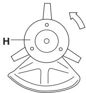
natural_image
Technical line drawing of a mechanical component with labeled part H and directional arrow (no text or symbols beyond basic geometry)natural_image
Diagram of a coiled cable or wire structure with labeled points A, B, and C (no text or symbols beyond labels)Bränslesäkerhet
Starta aldrig maskinen:
natural_image
Illustration of fuel injection and distribution with a container and pump (no text or symbols)
natural_image
Illustration of a person in protective gear holding a device (no text or symbols visible)Kontroll före start
natural_image
Two abstract line drawings with arrows pointing to curved and circular shapes, no text or symbols present.natural_image
Simple line drawing of a circular object with a downward arrow pointing to its center (no text or symbols)natural_image
Line drawing of a garment sleeve with a knob and arrow indicating direction (no text or symbols)natural_image
Simple line drawing of a mechanical component with no text or symbolsStart och stopp


natural_image
Technical line drawing of a mechanical component with no visible text or symbolsnatural_image
Technical line drawing of a vehicle engine compartment with no visible text or symbols
natural_image
Illustration of a person in safety gear handling equipment (no text or symbols visible)natural_image
Line drawing of a mechanical device with a prohibition symbol on its side (no text or labels)Stopp

natural_image
Technical line drawing of a mechanical component with an arrow indicating direction (no text or symbols)natural_image
Line drawing of a person spraying a shrub outdoors, no text or symbols presentnatural_image
Line drawing of a person in full protective suit holding a tool, no text or symbols presentnatural_image
Illustration of a hand using a tool to lift pine needles, no text or symbols presentnatural_image
Simple line drawing of a grassy field with a mounted tool (no text or symbols)natural_image
Simple line drawing of a shovel digging grass with a tool, no text or symbols presentnatural_image
Simple line drawing of a grassy field with a small mechanical component above it (no text or symbols)natural_image
Diagram of a hand holding a mechanical lever with rotating components (no text or symbols)natural_image
Technical line drawing of a vehicle engine compartment with no visible text or symbols
natural_image
Technical line drawing of an automotive engine assembly (no text or symbols visible)Kylsystemet består av:
natural_image
Technical line drawing of a mechanical assembly with internal components (no text or symbols)natural_image
Line drawing of a car head assembly with a belt switch and directional control panel (no text or symbols)1 Bränslefilter
natural_image
Diagram of a mechanical joint or clamp mechanism with an arrow indicating direction (no text or symbols present)Tändstift

Michael Kullberg, Business manager
Symboler
natural_image
Diagram of a mechanical component with three circular icons below (no text or symbols)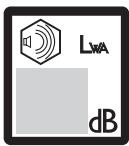
Hvad er hvad?
natural_image
Line drawing of a helmet and safety goggles (no text or symbols)H∅REVÆRN
natural_image
Line drawing of glasses and accessories (no text or symbols)HANDSKER
natural_image
Technical line drawing of a mechanical component with an arrow indicating direction (no text or symbols)natural_image
Technical line drawing of a mechanical component with an upward arrow indicating motion (no text or symbols)natural_image
Diagram of a mechanical device with directional arrows indicating motion or force (no text or symbols)Stopkontakt
natural_image
Technical line drawing of a mechanical component with a downward arrow indicating motion (no text or symbols)natural_image
Line drawing of a mechanical component with blades and a central knob (no text or symbols)natural_image
Technical line drawing of a mechanical assembly with no visible text or symbols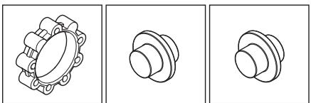
natural_image
Three technical line drawings of mechanical components, showing different types of housing or assemblies (no text or symbols present)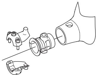
natural_image
Technical line drawing of a mechanical assembly with exploded view (no text or symbols)natural_image
Line drawing of a mechanical device with two circular buttons and a handle (no text or symbols)natural_image
Line drawing of a mechanical switch or lever device (no text or symbols)natural_image
Technical line drawing of a mechanical component with an arrow indicating direction (no text or symbols)natural_image
Technical illustration of a mechanical component with a nut and rotating arrow (no text or symbols)natural_image
Three abstract geometric shapes with circular centers and curved surfaces, no text or symbols presentnatural_image
Technical line drawing of a mechanical component and its cross-sectional view (no text or symbols)Grundregler

natural_image
Three abstract line drawings: a star-like shape, a triangular shape, and a cylindrical object with curved lines (no text or symbols)natural_image
Diagram of a shield blade with an arrow indicating upward motion (no text or symbols)natural_image
Two diagrams showing a tool interacting with a stylized shape, one with an arrow indicating direction (no text or symbols)
natural_image
Three technical illustrations of mechanical components: a cylindrical fan, a rectangular device with a circular element, and a coiled spring (no text or symbols)natural_image
Technical line drawing of a mechanical clamp or clamping device with no visible text or symbolsnatural_image
Technical line drawing of a mechanical clamp or tool assembly (no text or symbols)natural_image
Line drawing of a mechanical clamp or clamping mechanism (no text or symbols)
natural_image
Technical line drawing of a mechanical assembly with two views (front and side), no text or symbols present.
Montering af trimmerbeskyttelse og trimmerhoved
natural_image
Two technical line drawings of a mechanical component with labeled parts (H), showing angular and radial features without any text or symbols.natural_image
Illustration of a fuel pump with a bottle pouring liquid into a flax (no text or symbols)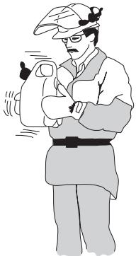
natural_image
Illustration of a person in traditional attire holding an object, no text or symbols presentKontrol før start
natural_image
Two abstract line drawings with arrows pointing to a central circular feature, no text or symbols present.natural_image
Simple line drawing of a circular object with a downward arrow pointing to its center (no text or symbols)natural_image
Line drawing of a garment sleeve with a knob and arrow indicating direction (no text or symbols)natural_image
Line drawing of a mechanical component with no visible text or symbolsStart og stop


natural_image
Technical line drawing of a mechanical component with no visible text or symbolsChoker: Stil chokeren i chokestilling.
natural_image
Technical line drawing of a car engine compartment with no visible text or symbols
ADVARSEL! Når motoren startes med chokeren i choker- eller startgasstilling, begynder skæreudstyret straks at rotere.
natural_image
Illustration of a person in safety gear using a tool on a workbench (no text or symbols)natural_image
Line drawing of a mechanical device with a prohibition symbol overlay (no text or symbols present)Stop

natural_image
Line drawing of a mechanical component with a downward arrow indicating force or direction (no text or symbols)natural_image
Line drawing of a person spraying a tree with a shoveling machine (no text or symbols)natural_image
Line drawing of a person in full protective gear holding a tool, no text or symbols presentnatural_image
Illustration of a manual sprinkler with a bucket, no text or symbols presentnatural_image
Simple line drawing of a grassy field with a mounted tool (no text or symbols)natural_image
Simple line drawing of a shovel digging grass on a branch (no text or symbols)natural_image
Simple line drawing of a grassy field with a small mechanical component above (no text or symbols)- Undgå at lade trimmerhovedet have permanent kontakt med jorden ved normal klipning. En sådan kontakt kan medføre skader og slitage på trimmerhovedet.
Fejning
natural_image
Diagram of a hand holding a pole with a rotating arm, showing motion direction (no text or symbols)natural_image
Technical line drawing of a car engine compartment with no visible text or symbols
natural_image
Technical line drawing of an automotive engine assembly (no text or symbols visible)natural_image
Technical line drawing of a mechanical assembly with internal components (no text or symbols)1 Brændstofffilter
natural_image
Diagram of a mechanical joint or clamp mechanism with an arrow indicating direction (no text or symbols present)Tændrør

Michael Kullberg, Business manager
Tunnukset
natural_image
Circular icon with a stylized human face wearing a helmet and sunglasses, enclosed in a black border (no text or symbols)
max 10000 rpm
natural_image
Pure mechanical component diagram without any text, numbers, or symbols
Koneen osat
natural_image
Line drawing of a helmet and safety goggles (no text or symbols)KUULONSUOJAIMET
natural_image
Technical line drawing of a mechanical tool with a curved arrow indicating rotation (no text or symbols)natural_image
Diagram of a mechanical component with an upward arrow indicating motion or force (no text or symbols present)natural_image
Diagram of a mechanical tool with directional arrows indicating motion or force (no text or symbols)Pysäytin
natural_image
Technical line drawing of a mechanical component with an arrow indicating direction (no text or symbols)natural_image
Line drawing of a mechanical component with blades and a knob (no text or symbols)natural_image
Technical line drawing of a mechanical assembly with no visible text or symbols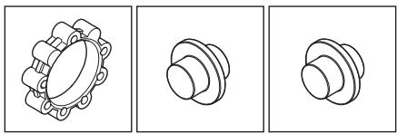
natural_image
Three technical line drawings of mechanical components, showing different types of housing or assemblies (no text or symbols present)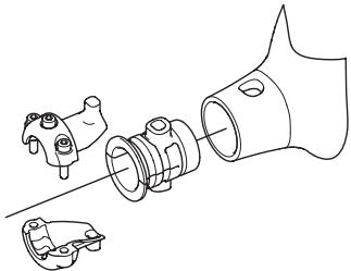
natural_image
Technical line drawing of a mechanical assembly with exploded view (no text or symbols)natural_image
Line drawing of a mechanical device with two circular ports and a handle (no text or symbols)natural_image
Line drawing of a mechanical switch or lever assembly (no text or symbols)natural_image
Technical line drawing of a mechanical component with an arrow indicating direction (no text or symbols)natural_image
Technical line drawing of a mechanical component with a wrench and a circular arrow indicating rotational motion (no text or symbols)natural_image
Three abstract geometric shapes with circular centers and triangular bases, no text or symbols presentnatural_image
Technical line drawing of a mechanical component with a flanged base and a triangular cross-section (no text or symbols)Perussäännöt

natural_image
Three abstract line drawings: a star-like shape, a triangular shape, and a circular mechanical component with curved lines (no text or symbols)natural_image
Simple line drawing of a shield blade with an arrow indicating upward motion (no text or symbols)natural_image
Two diagrams showing a tool interacting with a blade-like object, one with an arrow indicating direction (no text or symbols)
natural_image
Three technical illustrations: a kettle, a washing machine, and a spool (no text or symbols)natural_image
Technical line drawing of a mechanical clamp or clamping device with no visible text or symbolsnatural_image
Technical line drawing of a mechanical clamp or bracket assembly (no text or symbols)natural_image
Line drawing of a mechanical clamp or clamping mechanism (no text or symbols)
natural_image
Technical line drawing of a mechanical assembly with cross-sectional and top views (no text or symbols)
natural_image
Pure technical line drawing of a mechanical component with no text or symbols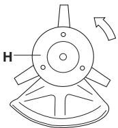
natural_image
Technical line drawing of a mechanical component with labeled part H and directional arrow (no text or symbols beyond basic diagram)natural_image
Illustration of a fuel pump with a bottle pouring liquid into a flax (no text or symbols)natural_image
Two abstract line drawings with arrows pointing to a central circular feature, no text or symbols present.natural_image
Simple line drawing of a circular object with a downward arrow pointing to its center (no text or symbols)natural_image
Line drawing of a garment collar with a knob and arrow indicating direction (no text or symbols)natural_image
Line drawing of a mechanical component with no visible text or symbolsnatural_image
Technical line drawing of a mechanical assembly with no visible text or symbolsRikastin: Aseta rikastin rikastusasentoon.

natural_image
Technical line drawing of a mechanical component with an inset showing a close-up view of the internal structure (no text or symbols present)natural_image
Illustration of a person in safety gear using a tool on a workbench (no text or symbols)natural_image
Line drawing of a mechanical device with a prohibition symbol overlay (no text or symbols present)Pysäytys

natural_image
Technical line drawing of a mechanical component with a downward arrow indicating force or direction (no text or symbols)Yleiset työohjeet
TÄRKEÄÄ!
natural_image
Line drawing of a person spraying a shrub outdoors, with trees and grass in the background (no text or symbols)natural_image
Line drawing of a person in full protective gear holding a tool, with no text or symbols present.natural_image
Illustration of a hand using a tool to lift a pine branch (no text or symbols)natural_image
Simple line drawing of a grassy slope with a tool, no text or symbols presentnatural_image
Simple line drawing of a manual tool cutting grass with a tool, no text or symbols presentnatural_image
Simple line drawing of a grassy field with a small mechanical component above it (no text or symbols)natural_image
Diagram of a hand holding a tool with a rotating wheel and directional arrows indicating motion (no text or symbols)natural_image
Technical line drawing of a car engine compartment with no visible text or symbols
natural_image
Technical line drawing of an automotive engine assembly (no text or symbols visible)natural_image
Technical line drawing of a mechanical assembly with internal components and housing (no text or symbols)natural_image
Diagram of a car head assembly with a belt switch and directional control panel (no text or symbols)natural_image
Mechanical assembly diagram showing a lever and pivot point (no text or symbols)Sytytystulppa

natural_image
Circular icon with a stylized face wearing sunglasses and a helmet, enclosed in a black border (no text or symbols)max 10000 rpm


natural_image
Diagram of a mechanical component with gear and triangular elements, no text or symbols present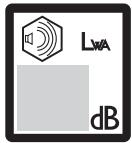

Hva er hva?
natural_image
Line drawing of a helmet and gear assembly (no text or symbols)H∅RSELSVERN
natural_image
Line drawing of glasses and accessories (no text or symbols)HANSKER
natural_image
Technical line drawing of a mechanical tool with a curved arrow indicating rotation (no text or symbols)natural_image
Diagram of a mechanical component with an upward arrow indicating motion or force (no text or symbols present)natural_image
Diagram of a mechanical tool with directional arrows indicating motion or force (no text or symbols)Stoppbryter
natural_image
Technical line drawing of a mechanical component with an arrow indicating direction (no text or symbols)natural_image
Line drawing of a mechanical component resembling a fan or impeller (no text or symbols)natural_image
Technical line drawing of a mechanical device with no visible text or symbols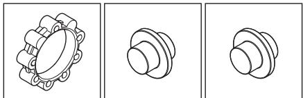
natural_image
Three technical line drawings of mechanical components, showing front, side, and top views (no text or symbols)
natural_image
Technical line drawing of a mechanical assembly with exploded view (no text or symbols)natural_image
Line drawing of a mechanical device with two circular ports and a handle (no text or symbols)Kontroller regelmessig at lyddemperen sitter fast i maskinen.
natural_image
Line drawing of a mechanical switch or lever device (no text or symbols)natural_image
Technical line drawing of a mechanical component with an arrow indicating direction (no text or symbols)natural_image
Technical illustration of a mechanical component with a nut and rotating arrow (no text or symbols)natural_image
Three abstract geometric shapes with internal dots, no text or symbols presentnatural_image
Line drawings of a pot and a triangular plate (no text or symbols)Grunnregler

natural_image
Three abstract line drawings: a triangular shape, a triangular cross-section, and a cylindrical mechanical component with curved ends (no text or symbols)natural_image
Simple line drawing of a shield with a flag and arrow, no text or symbols presentnatural_image
Two diagrams showing a tool interacting with a blade-like object, one with an arrow indicating direction (no text or symbols)
natural_image
Three technical illustrations of mechanical components: a cylindrical fan, a rectangular box with a circular element, and a coiled spring (no text or symbols)natural_image
Technical line drawing of a mechanical clamp or clamping device with no visible text or symbols- Skyv distansestykket inn i sporet i loophåndtaket.
• Monter mutteren og skruen. Ikke trekk til for hardt. - J-håndtaket monteres i loophåndtaket med tre skruer som vist på bildet.
natural_image
Technical line drawing of a mechanical clamp or bracket assembly (no text or symbols)natural_image
Line drawing of a mechanical clamp or clamping mechanism (no text or symbols)
natural_image
Technical line drawing of two mechanical assembly configurations (no text or symbols)
• Monter medbringeren (B) på den utgående akselen.
- Vri rundt klingeakselen til ett av hullene i medbringeren stemmer overens med tilsvarende hull i girhuset.
• Før låsepinnen (C) inn i hullet slik at akselen låses.
- Plasser klingen (D), støttekoppen (E) og støtteflensen (F) på den utgående akselen.
- Monter mutteren (G). Mutteren trekkes til med et moment på 35-50 Nm (3,5-5 kpm). Bruk pipenøkkelen
natural_image
Pure technical line drawing of a mechanical component with no text or symbols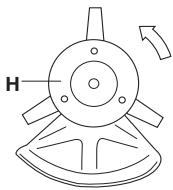
natural_image
Technical line drawing of a mechanical component with labeled part H and directional arrow (no text or symbols beyond basic geometry)natural_image
Illustration of fuel injection from a flint and a gas can with an oil drop (no text or symbols)Kontroll før start
natural_image
Two abstract line drawings with arrows indicating direction, no text or symbols presentnatural_image
Simple line drawing of a circular object with a downward arrow pointing to its center (no text or symbols)natural_image
Line drawing of a garment sleeve with a knob and arrow indicating direction (no text or symbols)natural_image
Simple line drawing of a mechanical component with no text or symbolsStart og stopp


Tenning: Still stoppbryteren i startstilling.
natural_image
Technical line drawing of a mechanical component with an arrow indicating a specific part (no text or symbols present)Choke: Still chokehendelen i choke-stilling.
natural_image
Technical line drawing of a mechanical component with an inset detail showing internal components (no text or symbols)
natural_image
Illustration of a person wearing safety gear and using a tool on a box (no text or symbols visible)natural_image
Line drawing of a mechanical device with a prohibition symbol on its side (no text or labels)Stopp

natural_image
Technical line drawing of a mechanical component with an arrow indicating direction (no text or symbols)natural_image
Line drawing of a person spraying a shrub outdoors (no text or symbols)natural_image
Line drawing of a person in full protective gear holding a tool, with no text or symbols present.natural_image
Illustration of a hand using a manual tool to lift a pine branch (no text or symbols)natural_image
Simple line drawing of a grassy field with a grasshopper (no text or symbols)natural_image
Simple line drawing of a shovel digging grass with a tool, no text or symbols presentnatural_image
Simple line drawing of a grassy field with a small mechanical component above it (no text or symbols)natural_image
Diagram of a hand holding a mechanical lever with rotating components (no text or symbols)natural_image
Technical line drawing of a vehicle engine compartment with no visible text or symbols
natural_image
Technical line drawing of an automotive engine assembly (no text or symbols visible)Kjølesystemet består av:
1 Kjøleflenser på sylinderen.
2 Luftinntak.
natural_image
Technical line drawing of a mechanical assembly with internal components (no text or symbols)natural_image
Technical line drawing of a car head assembly with a belt switch and directional control panel (no text or symbols)1 Bensinfilter
natural_image
Diagram of a mechanical joint or bracket with an arrow indicating direction (no text or symbols present)Tennplugg

WARNING! A clearing saw, brushcutter or trimmer can be dangerous if used incorrectly or carelessly, and can cause serious or fatal injury to the operator or others. It is extremely important that you read and understand the contents of this operator's manual.
Please read the operator's manual carefully and make sure you understand the instructions before using the machine.
Always wear:
• A protective helmet where there is a risk of falling objects
• Approved hearing protection
• Approved eye protection
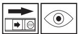
Max. speed of output shaft, rpm


This product is in accordance with applicable EC directives.
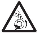
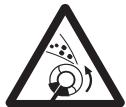
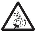
Watch out for thrown objects and ricochets.
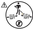
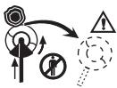
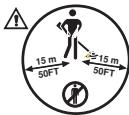
The operator of the machine must ensure, while working, that no persons or animals come closer than 15 metres.
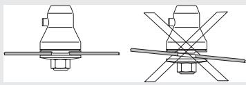
Machines fitted with saw blades or grass blades can be thrown violently to the side when the blade comes into contact with a fixed object. This is called blade thrust. The blade is capable of amputating an arm or leg.
Always keep people and animals at least 15 metres from the machine.
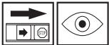
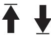
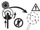
Arrows which show limits for handle positioning.
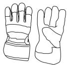
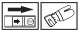
Always wear approved protective gloves.


Wear sturdy, non-slip boots.
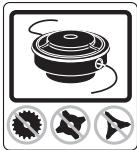
Only use non-metallic, flexible cutting attachments, i.e. trimmer heads with trimmer cord.
Noise emission to the environment according to the European Community's Directive. The machine's emission is specified in chapter Technical data and on label.
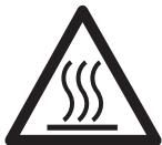
Keep all parts of your body away from hot surfaces.
Other symbols/decals on the machine refer to special certification requirements for certain markets.
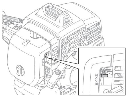
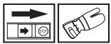
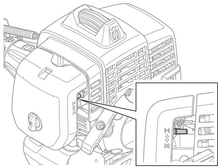
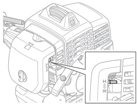
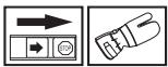
Switch off the engine by moving the stop switch to the STOP position before carrying out any checks or maintenance.
Always wear approved protective gloves.
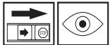
Regular cleaning is required.
Visual check.

natural_image
Diagram of a mechanical component with three circular icons below (no text or symbols)
Contents
KEY TO SYMBOLS
Symbols 176
CONTENTS
Contents 177
Note the following before starting: 177
INTRODUCTION
Dear Customer, 178
WHAT IS WHAT?
What is what? 179
GENERAL SAFETY PRECAUTIONS
Important 180
Personal protective equipment 180
Machine's safety equipment 181
Cutting equipment 184
ASSEMBLY
Fitting the J-handle 186
Fitting blades and trimmer heads 186
Fitting the transport guard 187
FUEL HANDLING
Fuel safety 188
Fuel 188
Fuelling 189
STARTING AND STOPPING
Check before starting 190
Starting and stopping 190
WORKING TECHNIQUES
General working instructions 192
MAINTENANCE
Carburettor 195
Muffler 195
Cooling system 196
Air filter 196
Fuel filter 196
Bevel gear 196
Spark plug 197
Maintenance schedule 198
TECHNICAL DATA
Technical data 199
EC-declaration of conformity 200
Note the following before starting:
Please read the operator's manual carefully.

WARNING! Long-term exposure to noise can result in permanent hearing impairment. So always use approved hearing protection.

WARNING! Under no circumstances may the design of the machine be modified without the permission of the manufacturer. Always use genuine accessories. Non-authorized modifications and/or accessories can result in serious personal injury or the death of the operator or others.

WARNING! A clearing saw, brushcutter or trimmer can be dangerous if used incorrectly or carelessly, and can cause serious or fatal injury to the operator or others. It is extremely important that you read and understand the contents of this operator's manual.
Dear Customer,
Congratulations on your choice to buy a Husqvarna product! Husqvarna is based on a tradition that dates back to 1689, when the Swedish King Karl XI ordered the construction of a factory on the banks of the Husqvarna River, for production of muskets. The location was logical, since water power was harnessed from the Huskvarna River to create the water-powered plant. During the more than 300 years of beeing, the Husqvarna factory has produced a lot of different products, from wood stoves to modern kitchen appliances, sewing machines, bicycles, motorcycles etc. In 1956, the first motor driven lawn mowers appeared, followed by chain saws in 1959, and it is within this area Husqvarna is working today.
Today Husqvarna is one of the leading manufacturers in the world of forest and garden products, with quality as our highest priority. The business concept is to develop, manufacture and market motor driven products for forestry and gardening as well as for building and construction industry. Husqvarna's aim is also to be in the front edge according to ergonomics, usability, security and environmental protection. That is the reason why we have developed many different features to provide our products within these areas.
We are convinced that you will appreciate with great satisfaction the quality and performance of our product for a very long time to come. The purchase of one of our products gives you access to professional help with repairs and service whenever this may be necessary. If the retailer who sells your machine is not one of our authorised dealers, ask for the address of your nearest service workshop.
It is our wish that you will be satisfied with your product and that it will be your companion for a long time. Think of this operator's manual as a valuable document. By following its' content (using, service, maintenance etc) the life span and the second-hand value of the machine can be extended. If you will sell this machine, make sure that the buyer will get the operator's manual.
Thank you for using a Husqvarna product.
Husqvarna AB has a policy of continuous product development and therefore reserves the right to modify the design and appearance of products without prior notice.
WHAT IS WHAT?
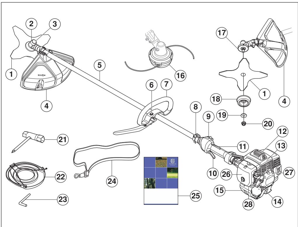
What is what?
1 Blade
2 Bevel gear
3 Grease filler cap, bevel gear
4 Cutting attachment guard
5 Shaft
6 Handle adjustment
7 J-handle
8 Support eyes for harness
9 Stop switch
10 Throttle control
11 Throttle lockout
12 Spark plug cap and spark plug
13 Cylinder cover
14 Starter handle
15 Fuel tank
16 Trimmer head
17 Drive disc
18 Support cup
19 Support flange
20 Locking nut
21 Socket spanner
22 Transport guard
23 Locking pin
24 Harness
25 Operator's manual
26 Air filter cover
27 Choke control
28 Air purge
Important
IMPORTANT!
The machine is only designed for trimming grass.
The only accessories you can operate with this engine unit are the cutting attachments we recommend in the chapter on Technical data.
Never use the machine if you are tired, if you have drunk alcohol, or if you are taking medication that could affect your vision, your judgement or your co-ordination.
Wear personal protective equipment. See instructions under the heading "Personal protective equipment".
Never use a machine that has been modified in any way from its original specification.
Never use a machine that is faulty. Carry out the checks, maintenance and service instructions described in this manual. Some maintenance and service measures must be carried out by trained and qualified specialists. See instructions under the heading Maintenance.
All covers, guards and handles must be fitted before starting. Ensure that the spark plug cap and ignition lead are undamaged to avoid the risk of electric shock.
The machine operator must ensure that no people or animals come closer than 15 metres while working. When several operators are working in the same area the safety distance should be at least twice the tree height and no less than 15 metres.

WARNING! The ignition system of this machine produces an electromagnetic field during operation. This field may under some circumstances interfere with pacemakers. To reduce the risk of serious or fatal injury, we recommend persons with pacemakers to consult their physician and the pacemaker manufacturer before operating this machine.

WARNING! Running an engine in a confined or badly ventilated area can result in death due to asphyxiation or carbon monoxide poisoning.
Personal protective equipment
IMPORTANT!
A clearing saw, brushcutter or trimmer can be dangerous if used incorrectly or carelessly, and can cause serious or fatal injury to the operator or others. It is extremely important that you read and understand the contents of this operator's manual.
You must use approved personal protective equipment whenever you use the machine. Personal protective equipment cannot eliminate the risk of injury but it will reduce the degree of injury if an accident does happen. Ask your dealer for help in choosing the right equipment.

WARNING! Listen out for warning signals or shouts when you are wearing hearing protection. Always remove your hearing protection as soon as the engine stops.
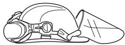
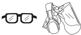
HELMET
A protective helmet where there is a risk of falling objects
natural_image
Line drawing of a helmet and safety goggles (no text or symbols)HEARING PROTECTION
Wear hearing protection that provides adequate noise reduction.
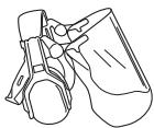
EYE PROTECTION
Always wear approved eye protection. If you use a visor then you must also wear approved protective goggles. Approved protective goggles must comply with standard ANSI Z87.1 in the USA or EN 166 in EU countries.
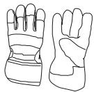
natural_image
Line drawing of glasses and accessories (no text or symbols)GLOVES
Gloves should be worn when necessary, e.g., when fitting cutting attachments.
BOOTS
Wear boots with steel toe-caps and non-slip sole.

CLOTHING
Wear clothes made of a strong fabric and avoid loose clothing that can catch on twigs and branches. Always wear heavy, long pants. Do not wear jewellery, shorts sandals or go barefoot. Secure hair so it is above shoulder level.
FIRST AID KIT
Always have a first aid kit nearby.

Machine's safety equipment
This section describes the machine's safety equipment, its purpose, and how checks and maintenance should be carried out to ensure that it operates correctly. See the "What is what?" section to locate where this equipment is positioned on your machine.
The life span of the machine can be reduced and the risk of accidents can increase if machine maintenance is not carried out correctly and if service and/or repairs are not carried out professionally. If you need further information please contact your nearest service workshop.
IMPORTANT! All servicing and repair work on the machine requires special training. This is especially true of the machine's safety equipment. If your machine fails any of the checks described below you must contact your service agent. When you buy any of our products we guarantee the availability of professional repairs and service. If the retailer who sells your machine is not a servicing dealer, ask him for the address of your nearest service agent.

WARNING! Never use a machine with faulty safety equipment. The machine's safety equipment must be checked and maintained as described in this section. If your machine fails any of these checks contact your service agent to get it repaired.
Throttle lockout
The throttle lockout is designed to prevent accidental operation of the throttle control. When you press the lock (A) (i.e. when you grasp the handle) it releases the throttle control (B). When you release the handle the throttle control and the throttle lockout both move back to their
original positions. This movement is controlled by two independent return springs. This arrangement means that the throttle control is automatically locked at the idle setting.
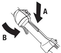
Make sure the throttle control is locked at the idle setting when the throttle lockout is released.
natural_image
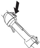
Technical line drawing of a mechanical component with an arrow indicating direction (no text or symbols)Press the throttle lockout and make sure it returns to its original position when you release it.
natural_image
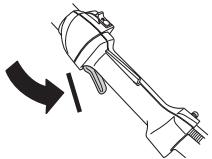
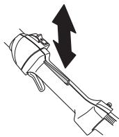
Technical line drawing of a mechanical component with an upward arrow indicating motion (no text or symbols)Check that the throttle control and throttle lockout move freely and that the return springs work properly.
natural_image
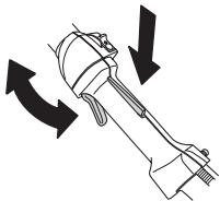
Diagram of a mechanical device with directional arrows indicating motion or force (no text or symbols)See instructions under the heading Start. Start the machine and apply full throttle. Release the throttle and check that the cutting attachment stops and remains at a standstill. If the cutting attachment rotates with the throttle in the idle position then the carburettor idle setting must be checked. See instructions under the heading Maintenance.
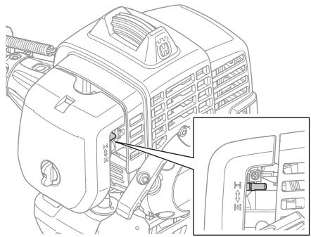
Stop switch
Use the stop switch to switch off the engine.
natural_image
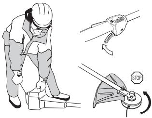
Technical line drawing of a mechanical component with a downward arrow indicating force or direction (no text or symbols)Start the engine and make sure the engine stops when you move the stop switch to the stop setting.
Cutting attachment guard
This guard is intended to prevent loose objects from being thrown towards the operator. The guard also protects the operator from accidental contact with the cutting attachment.
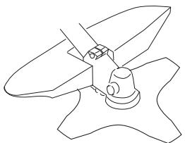
natural_image
Line drawing of a mechanical component with blades and a central hub (no text or symbols)Check that the guard is undamaged and not cracked. Replace the guard if it has been exposed to impact or is cracked.
Always use the recommended guard for the cutting attachment you are using. See chapter on Technical data.

WARNING! Never use a cutting attachment without an approved guard. See the chapter on Technical data. If an incorrect or faulty guard is fitted this can cause serious personal injury.
Vibration damping system
Your machine is equipped with a vibration damping system that is designed to minimize vibration and make operation easier.
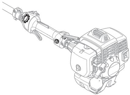
natural_image
Technical line drawing of a mechanical device with no visible text or symbols
natural_image
Three technical line drawings of mechanical components, showing different types of housing or assemblies (no text or symbols present)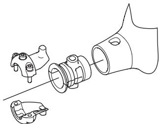
natural_image
Technical line drawing of a mechanical assembly with no visible text or symbolsUsing incorrectly wound cord or a blunt or incorrect cutting attachment (wrong type or incorrectly filed, see instructions under the heading Filing the blade) increases the level of vibration.
The machine's vibration damping system reduces the transfer of vibration between the engine unit/cutting equipment and the machine's handle unit.
Regularly check the vibration damping units for cracks or deformation. Check that the vibration damping element is undamaged and securely attached.

WARNING! Overexposure to vibration can lead to circulatory damage or nerve damage in people who have impaired circulation. Contact your doctor if you experience symptoms of overexposure to vibration. Such symptoms include numbness, loss of feeling, tingling, pricking, pain, loss of strength, changes in skin colour or condition. These symptoms normally appear in the fingers, hands or wrists. The risk increases at low temperatures.
GENERAL SAFETY PRECAUTIONS
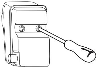
Muffler
The muffler is designed to keep noise levels to a minimum and to direct exhaust fumes away from the user. A muffler fitted with a catalytic converter is also designed to reduce harmful exhaust gases.
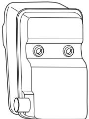
natural_image
Line drawing of a mechanical device with two circular ports and a handle (no text or symbols)For mufflers it is very important that you follow the instructions on checking, maintaining and servicing your machine.
Never use a machine that has a faulty muffler.
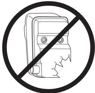
Regularly check that the muffler is securely attached to the machine.
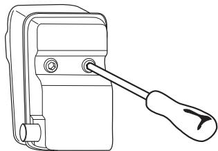
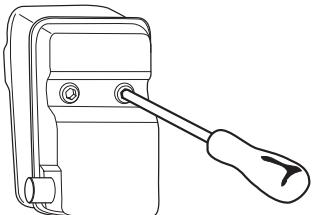
natural_image
Line drawing of a mechanical switch or lever device with a screwdriver (no text or symbols)If the muffler on your machine is fitted with a spark arrestor mesh this must be cleaned regularly. A blocked mesh will cause the engine to overheat and may lead to serious damage.

WARNING! Mufflers fitted with catalytic converters get very hot during use and remain so for some time after stopping. This also applies at idle speed. Contact can result in burns to the skin. Remember the risk of fire!

WARNING! The inside of the muffler contain chemicals that may be carcinogenic. Avoid contact with these elements in the event of a damaged muffler.

WARNING! Bear in mind that: The exhaust fumes from the engine are hot and may contain sparks which can start a fire. Never start the machine indoors or near combustible material!
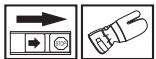
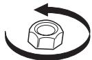
Locking nut
A locking nut is used to secure some types of cutting attachment.
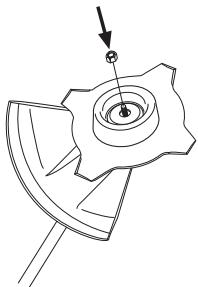
natural_image
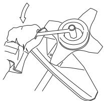
Technical line drawing of a mechanical component with a central hub and arrow indicator (no text or symbols)When fitting, tighten the nut in the opposite direction to the direction of rotation of the cutting attachment. To remove it, undo the nut in the same direction as the cutting attachment rotates. (CAUTION! The nut has a left-hand thread.) Tighten the nut using the socket spanner.
natural_image
Line drawing of a hand using a tool to lift a mechanical component (no text or symbols)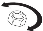
The nylon lining inside the locking nut must not be so worn that you can turn it by hand. The lining should offer a resistance of at least 1.5 Nm. The nut should be replaced after it has been put on approx. 10 times.
Cutting equipment
This section describes how to choose and maintain your cutting equipment in order to:
- Reduce the risk of blade thrust.
- Obtain maximum cutting performance.
- Extend the life of cutting equipment.
IMPORTANT!
Only use cutting attachments with the guards we recommend! See the chapter on Technical data.
Refer to the instructions for the cutting attachment to check the correct way to load the cord and the correct cord diameter.
Keep the teeth of the blade correctly sharpened! Follow our recommendations. Also refer to the instructions on the blade packaging.

WARNING! Always stop the engine before doing any work on the cutting attachment. This continues to rotate even after the throttle has been released. Ensure that the cutting attachment has stopped completely and disconnect the HT lead from the spark plug before you start to work on it.

WARNING! Using an incorrect cutting attachment or an incorrectly sharpened blade increases the risk of blade thrust.
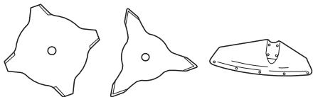
Cutting equipment
Grass blades and grass cutters are intended for cutting coarse grass.
natural_image
Three abstract geometric shapes with circular centers and curved surfaces, no text or symbols present.A trimmer head is intended for trimming grass.
natural_image
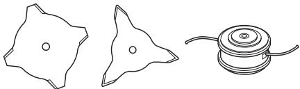
Technical line drawing of a mechanical component with a circular base and curved ends, alongside a triangular cross-section (no text or symbols)General rules

Only use cutting attachments with the guards we recommend! See the chapter on Technical data.
natural_image
Three abstract line drawings: a star-like shape, a triangular shape, and a cylindrical object with curved lines (no text or symbols)Keep the teeth of the blade correctly sharpened! Follow our instructions and use the recommended file gauge. An incorrectly sharpened or damaged blade increases the risk of accidents.
natural_image
Diagram of a shield with a flag and arrow indicating direction (no text or symbols)Check the cutting attachment for damage or cracks. A damaged cutting attachment should always be replaced.
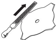
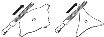
Sharpening grass cutters and grass blades
- See the cutting attachment packaging for correct sharpening instructions. Sharpen blades and cutters using a single-cut flat file.
- Sharpen all edges equally to maintain the balance of the blade.
natural_image
Two diagrams showing a tool interacting with a blade-like object, each with an arrow indicating direction (no text or symbols present)
WARNING! Always discard a blade that is bent, twisted, cracked, broken or damaged in any other way. Never attempt to straighten a twisted blade so that it can be reused. Only use original blades of the specified type.
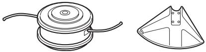
Trimmer head
IMPORTANT!
Always ensure the trimmer cord is wound tightly and evenly around the drum, otherwise the machine will generate harmful vibration.
- Only use the recommended trimmer heads and trimmer cords. These have been tested by the manufacturer to suit a particular engine size. This is especially important when a fully automatic trimmer head is used. Only use the recommended cutting attachment. See the chapter on Technical data.
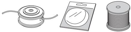
natural_image
Three technical illustrations of mechanical components: a cylindrical fan, a rectangular box with a circular element, and a coiled spring (no text or symbols)- Smaller machines generally require small trimmer heads and vice versa. This is because when clearing using a cord the engine must throw out the cord radially from the trimmer head and overcome the resistance of the grass being cleared.
- The length of the cord is also important. A longer cord requires greater engine power than a shorter cord of the same diameter.
- Make sure that the cutter on the trimmer guard is intact. This is used to cut the cord to the correct length.
- To increase the life of the cord it can be soaked in water for a couple of days. This will make the line tougher so that it lasts longer.
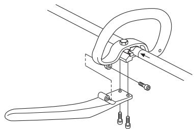
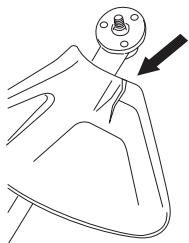
Fitting the J-handle

- Position the handle on the shaft. Note that the handle must be mounted below the arrow on the shaft.
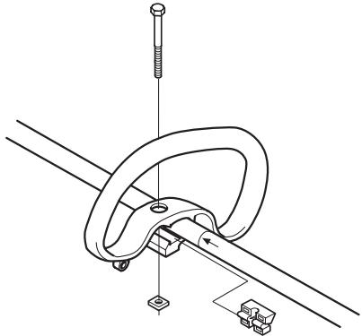
natural_image
Technical line drawing of a mechanical clamp or clamping device with no visible text or symbols- Slide the spacer into the slot in the loop handle.
• Fit the nut and screw. Do not overtighten. - Attach the J-handle to the loop handle using the three screws, as shown.
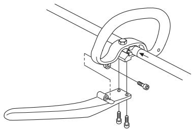
natural_image
Technical line drawing of a mechanical clamp or bracket assembly (no text or symbols)- Now adjust the trimmer to give a comfortable working position. Tighten the bolt/knob.
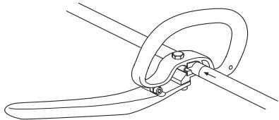
natural_image
Line drawing of a mechanical clamp or clamping device with no text or symbols
WARNING! Only grass blades/grass cutters or trimmer heads/plastic blades may be used when the J-handle is fitted. Saw blades must never be used with the J-handle.
Fitting blades and trimmer heads

WARNING!
When fitting the cutting attachment it is extremely important that the raised section on the drive disc/support flange engages correctly in the centre hole of the cutting attachment. If the cutting attachment is fitted incorrectly it can result in serious and/or fatal personal injury.
natural_image
Technical line drawing of two mechanical components with cross-sectional views (no text or symbols)
WARNING! Never use a cutting attachment without an approved guard. See the chapter on Technical data. If an incorrect or faulty guard is fitted this can cause serious personal injury.
IMPORTANT! If a saw blade or grass blade are to be used the machine must be equipped with the correct handlebar, blade guard and harness.
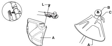
Fitting a blade guard, grass blade and grass cutter
- Hook the blade guard/combination guard (A) onto the fitting on the shaft and secure with the bolt (L). CAUTION! Use the recommended blade guard. See the Technical data section.
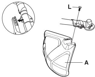
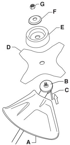
• Fit the drive disc (B) on the output shaft.
- Turn the blade shaft until one of the holes in the drive disc aligns with the corresponding hole in the gear housing.
- Insert the locking pin (C) in the hole to lock the shaft.
- Place the blade (D), support cup (E) and support flange (F) on the output shaft.
- Fit the nut (G). The nut must be tightened to a torque of 35-50 Nm (3.5-5 kpm). Use the socket spanner in the tool kit. Hold the shaft of the spanner as close to the blade guard as possible. To tighten the nut, turn the spanner in the opposite direction to the direction of rotation (Caution! left-hand thread).
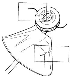
Fitting the trimmer guard and trimmer head

- Fit the correct trimmer guard (A) for use with the trimmer head. Hook the trimmer guard/combination guard onto the fitting on the shaft and secure with the bolt (L).
• Fit the drive disc (B) on the output shaft.
- Turn the blade shaft until one of the holes in the drive disc aligns with the corresponding hole in the gear housing.
- Insert the locking pin (C) in the hole to lock the shaft.
- Screw on the trimmer head/plastic blades (H) in the opposite direction to the direction of rotation.
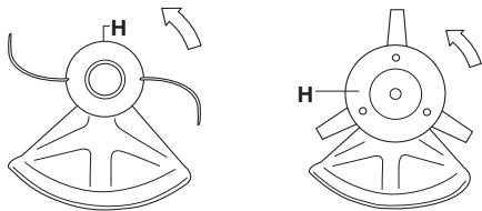
natural_image
Two technical line drawings of a mechanical component with labeled parts (H), showing angular and radial motion (no text or symbols)- To dismantle, follow the instructions in the reverse order.
Fitting the transport guard

1 Insert the blade in the transport guard (A).
2 Snap the two fasteners (B) into the slots (C) to secure the transport guard.
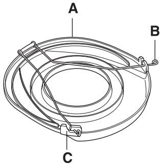
natural_image
Diagram of a coiled cable or hose with labeled components A, B, and C (no text or symbols beyond labels)Fuel safety
Never start the machine:
1 If you have spilt fuel on it. Wipe off the spillage and allow remaining fuel to evaporate.
2 If you have spilt fuel on yourself or your clothes, change your clothes. Wash any part of your body that has come in contact with fuel. Use soap and water.
3 If the machine is leaking fuel. Check regularly for leaks from the fuel cap and fuel lines.
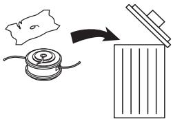
Transport and storage
- Store and transport the machine and fuel so that there is no risk of any leakage or fumes coming into contact with sparks or naked flames, for example, from electrical machinery, electric motors, electrical relays/ switches or boilers.
- When storing and transporting fuel always use approved containers intended for this purpose.
- When storing the machine for long periods the fuel tank must be emptied. Contact your local petrol station to find out where to dispose of excess fuel.
- Ensure the machine is cleaned and that a complete service is carried out before long-term storage.
- The transport guard must always be fitted to the cutting attachment when the machine is being transported or in storage.
- In order to prevent unintentional starting of the engine, the spark plug cap must always be removed during long-term storage, if the machine is not under close supervision and when performing all service measures.

WARNING! Take care when handling fuel. Bear in mind the risk of fire, explosion and inhaling fumes.
Fuel
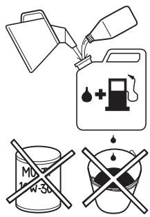
CAUTION! The machine is equipped with a two-stroke engine and must always been run using a mixture of petrol and two-stroke oil. It is important to accurately measure the amount of oil to be mixed to ensure that the correct mixture is obtained. When mixing small amounts of fuel, even small inaccuracies can drastically affect the ratio of the mixture.

WARNING! Fuel and fuel fumes are highly inflammable and can cause serious injury when inhaled or allowed to come in contact with the skin. For this reason observe caution when handling fuel and make sure there is adequate ventilation.
Petrol

CAUTION! Always use a quality petrol/oil mixture at least 90 octane (RON). If your machine is equipped with a catalytic converter (see chapter on Technical data) always use a good quality unleaded petrol/oil mixture. Leaded petrol will destroy the catalytic converter.
Use low-emission petrol, also known as alkylate petrol, if it is available.
natural_image
Illustration of a fuel pump with a bottle pouring liquid into a flax (no text or symbols)- The lowest octane recommended is 90 (RON). If you run the engine on a lower octane grade than 90 so-called knocking can occur. This gives rise to a high engine temperature, which can result in serious engine damage.
- When working at continuous high revs a higher octane rating is recommended.
Two-stroke oil
- For best results and performance use HUSQVARNA two-stroke engine oil, which is specially formulated for our air-cooled two-stroke engines.
- Never use two-stroke oil intended for water-cooled engines, sometimes referred to as outboard oil (rated TCW).
• Never use oil intended for four-stroke engines. - A poor oil quality and/or too high oil/fuel ratio may jeopardise function and decrease the life time of catalytic converters.
- Mixing ratio
1:50 (2%) with HUSQVARNA two-stroke oil.
1:50 (2%) with oils class JASO FC or ISO EGC formulated for air-cooled, two-stroke engines.
| Petrol, litre | Two-stroke oil, litre |
| 2% (1:50) | |
| 5 | 0,10 |
| 10 | 0,20 |
| 15 | 0,30 |
| 20 | 0,40 |
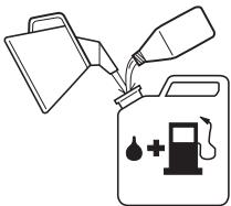
Mixing
• Always mix the petrol and oil in a clean container intended for fuel.
- Always start by filling half the amount of the petrol to be used. Then add the entire amount of oil. Mix (shake) the fuel mixture. Add the remaining amount of petrol.
- Mix (shake) the fuel mixture thoroughly before filling the machine's fuel tank.
natural_image
Illustration of a person in traditional attire holding a small object, no text or symbols present- Do not mix more than one month's supply of fuel at a time.
- If the machine is not used for some time the fuel tank should be emptied and cleaned.

WARNING! The catalytic converter muffler gets very hot during and after use. This also applies during idling. Be aware of the fire hazard, especially when working near flammable substances and/or vapours.
Fuelling


WARNING! Taking the following precautions, will lessen the risk of fire:
Do not smoke or place hot objects near fuel.
Always shut off the engine before refuelling.
Always stop the engine and let it cool for a few minutes before refuelling.
When refuelling, open the fuel cap slowly so that any excess pressure is released gently.
Tighten the fuel cap carefully after refuelling.
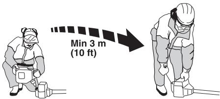
Always move the machine away from the refuelling area before starting.
• Always use a fuel container with an anti-spill valve.
- Clean the area around the fuel cap. Contamination in the tank can cause operating problems.
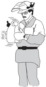
- Ensure that the fuel is well mixed by shaking the container before filling the tank.
Check before starting

- Never use the machine without a guard nor with a defective guard.
- All covers must be correctly fitted and undamaged before you start the machine.
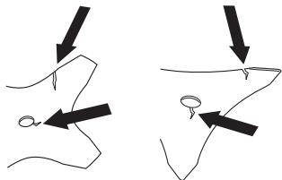
- Check the blade to ensure that no cracks have formed at the bottom of the teeth or by the centre hole. The most common reason why cracks are formed is that sharp corners have been formed at the bottom of the teeth while sharpening or that the blade has been used with dull teeth. Discard a blade if cracks are found.
natural_image
Two diagrams showing a hand holding a curved object with arrows indicating direction (no text or symbols)- Check that the support flange is not cracked due to fatigue or due to being tightened too much. Discard the support flange if it is cracked.
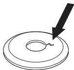
natural_image
Simple line drawing of a circular object with a downward arrow pointing to its center (no text or symbols)- Ensure the locking nut has not lost its captive force. The nut lock should have a locking force of at least 1.5 Nm. The tightening torque of the locking nut should be 35-50 Nm.
- Check that the blade guard is not damaged or cracked. Replace the blade guard if it is exposed to impact or is cracked.
natural_image
Line drawing of a garment sleeve with a knob and arrow indicating direction (no text or symbols)- Check that the trimmer head and trimmer guard are not damaged or cracked. Replace the trimmer head or
trimmer guard if they have been exposed to impact or are cracked.
natural_image
Simple line drawing of a mechanical component with no text or symbolsStarting and stopping


WARNING! The complete clutch cover and shaft must be fitted before the machine is started, otherwise the clutch can come loose and cause personal injury.
Always move the machine away from the refuelling area before starting. Place the machine on a flat surface. Ensure the cutting attachment cannot come into contact with any object.
Make sure no unauthorised persons are in the working area, otherwise there is a risk of serious personal injury. The safety distance is 15 metres.
Starting

Ignition: Set the stop switch to the start position.
STARTING AND STOPPING
Primer bulb: Press the air purge repeatedly until fuel begins to fill the bulb. The bulb need not be completely filled.
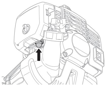
natural_image
Technical line drawing of a mechanical assembly with no visible text or symbolsChoke: Set the choke control in the choke position.

natural_image
Technical line drawing of a car engine compartment with no visible text or symbols
WARNING! When the engine is started with the choke in either the choke or start throttle positions the cutting attachment will start to rotate immediately.
Hold the body of the machine on the ground using your left hand (CAUTION! Not with your foot!). Grip the starter handle, slowly pull out the cord with your right hand until you feel some resistance (the starter pawls grip), now quickly and powerfully pull the cord. Never twist the starter cord around your hand.
Reset the choke when the engine fires, repeat pulling the cord until the engine starts.
CAUTION! Do not pull the starter cord all the way out and do not let go of the starter handle when the cord is fully extended. This can damage the machine.
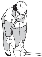
natural_image
Illustration of a person in safety gear handling equipment (no text or symbols visible)CAUTION! Do not put any part of your body in marked area. Contact can result in burns to the skin, or electrical shock if the spark plug cap has been damaged. Always use gloves. Do not use a machine with damaged spark plug cap.
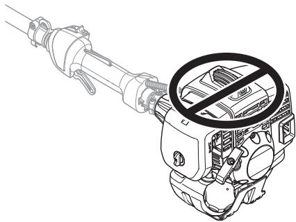
natural_image
Line drawing of a mechanical device with a prohibition symbol on its side (no text or labels)Stopping

Stop the engine by switching off the ignition.
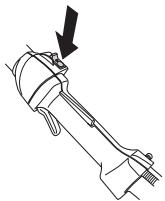
natural_image
Technical line drawing of a mechanical component with a downward arrow indicating motion (no text or symbols)General working instructions
IMPORTANT!
This section describes the basic safety precautions for working with clearing saws and trimmers.
If you encounter a situation where you are uncertain how to proceed you should ask an expert. Contact your dealer or your service workshop.
Avoid all usage which you consider to be beyond your capability.
You must understand the difference between forestry clearing, grass clearing and grass trimming before use.
Basic safety rules


1 Look around you:
- To ensure that people, animals or other things cannot affect your control of the machine.
- To ensure that people, animals, etc., do not come into contact with the cutting attachment or loose objects that are thrown out by the cutting attachment.
- CAUTION! Do not use the machine unless you are able to call for help in the event of an accident.
2 Inspect the working area. Remove all loose objects, such as stones, broken glass, nails, steel wire, string, etc. that could be thrown out or become wrapped around the cutting attachment.
3 Do not use the machine in bad weather, such as dense fog, heavy rain, strong wind, intense cold, etc. Working in bad weather is tiring and often brings added risks, such as icy ground, unpredictable felling direction, etc.
4 Make sure you can move and stand safely. Check the area around you for possible obstacles (roots, rocks, branches, ditches, etc.) in case you have to move suddenly. Take great care when working on sloping ground.
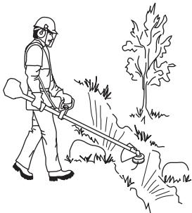
natural_image
Line drawing of a person spraying a tree with a hose, no text or symbols present5 Keep a good balance and a firm foothold.
6 Always hold the machine with both hands. Hold the machine on the right side of your body.
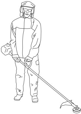
natural_image
Line drawing of a person in full protective gear holding a tool, no text or symbols present7 Keep the cutting attachment below waist level.
8 Switch off the engine before moving to another area. Fit the transport guard before carrying or transporting the equipment any distance.
9 Never put the machine down with the engine running unless you have it in clear sight.

WARNING! Neither the operator of the machine nor anyone else may attempt to remove the cut material while the engine is running or the cutting equipment is rotating, as this can result in serious injury.
Stop the engine and cutting equipment before you remove material that has wound around the blade shaft as otherwise there is a risk of injury. The bevel gear can get hot during use and may remain so for a while afterwards. You could get burnt if you touch it.

WARNING! Watch out for thrown objects. Always wear approved eye protection. Never lean over the cutting attachment guard. Stones, rubbish, etc. can be thrown up into the eyes causing blindness or serious injury.
Keep unauthorised persons at a distance. Children, animals, onlookers and helpers should be kept outside the safety zone of 15 m. Stop the machine immediately if anyone approaches. Never swing the machine around without first checking behind you to make sure no-one is within the safety zone.
Basic working techniques
Always slow the engine to idle speed after each working operation. Long periods at full throttle without any load on the engine can lead to serious engine damage.

WARNING! Sometimes branches or grass get caught between the guard and cutting attachment. Always stop the engine before cleaning.

WARNING! Machines fitted with saw blades or grass blades can be thrown violently to the side when the blade comes into contact with a fixed object. This is called blade thrust. A blade thrust can be violent enough to cause the machine and/or operator to be propelled in any direction, and possibly lose control of the machine. Blade thrust can occur without warning if the machine snags, stalls or binds. Blade thrust is more likely to occur in areas where it is difficult to see the material being cut.
Avoid cutting with the area of the blade between the 12 o'clock and 3 o'clock positions. Because of the speed of rotation of the blade, blade thrust can occur if you attempt to cut thick stems with this area of the blade.
Grass clearing using a grass blade

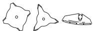
- Grass blades and grass cutters must not be used on woody stems.
- A grass blade is used for all types of tall or coarse grass.
- The grass is cut down with a sideways, swinging movement, where the movement from right-to-left is the clearing stroke and the movement from left-to-right is the return stroke. Let the left-hand side of the blade (between 8 and 12 o'clock) do the cutting.
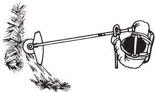
natural_image
Illustration of a hand using a tool to lift a tree with a handle (no text or symbols)- If the blade is angled to the left when clearing grass, the grass will collect in a line, which makes it easier to collect, e.g. by raking.
-
Try to work rhythmically. Stand firmly with your feet apart. Move forward after the return stroke and stand firmly again.
-
Let the support cup rest lightly against the ground. It is used to protect the blade from hitting the ground.
- Reduce the risk of material wrapping around the blade by following these instructions:
1 Always work at full throttle.
2 Avoid the previously cut material during the return stroke. - Stop the engine, unclip the harness and place the machine on the ground before you start to collect the cut material.
Grass trimming with a trimmer head


Trimming
- Hold the trimmer head just above the ground at an angle. It is the end of the cord that does the work. Let the cord work at its own pace. Never press the cord into the area to be cut.
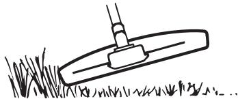
natural_image
Simple line drawing of a grassy field with a tool, no text or symbols present- The cord can easily remove grass and weeds up against walls, fences, trees and borders, however it can also damage sensitive bark on trees and bushes, and damage fence posts.
- Reduce the risk of damaging plants by shortening the cord to 10-12 cm and reducing the engine speed.
Clearing
- The clearing technique removes all unwanted vegetation. Keep the trimmer head just above the ground and tilt it. Let the end of the cord strike the ground around trees, posts, statues and the like. CAUTION! This technique increases the wear on the cord.
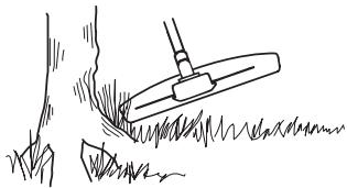
natural_image
Simple line drawing of a grassy field with a tool, no text or symbols present- The cord wears quicker and must be fed forward more often when working against stones, brick, concrete, metal fences, etc., than when coming into contact with trees and wooden fences.
- When trimming and clearing you should use less than full throttle so that the cord lasts longer and to reduce the wear on the trimmer head.
Cutting

- The trimmer is ideal for cutting grass that is difficult to reach using a normal lawn mower. Keep the cord parallel to the ground when cutting. Avoid pressing the trimmer head against the ground as this can ruin the lawn and damage the tool.

natural_image
Simple line drawing of a grassy field with a small mechanical component (no text or symbols)- Do not allow the trimmer head to constantly come into contact with the ground during normal cutting. Constant contact of this type can cause damage and wear to the trimmer head.
Sweeping
- The fan effect of the rotating cord can be used for quick and easy clearing up. Hold the cord parallel to and above the area to be swept and move the tool to and fro.

natural_image
Diagram of a hand holding a pole with a rotating arm, showing motion direction (no text or symbols)- When cutting and sweeping you should use full throttle to obtain the best results.
Carburettor
Adjusting the idle speed (T)
Check that the air filter is clean. When the idle speed is correct, the cutting attachment should not rotate. If adjustment is required, close (turn clockwise) the idle adjustment screw T, with the engine running, until the cutting attachment starts to rotate. Open (turn anticlockwise) the screw until the cutting attachment stops. The idle speed is correctly set when the engine runs smoothly in all positions, and there is a clear margin to the speed at which the cutting attachment starts to rotate.
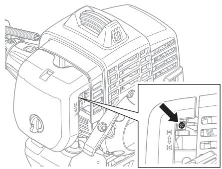
natural_image
Technical line drawing of a car engine compartment with no visible text or symbols
WARNING! If the idle speed cannot be adjusted so that the cutting attachment stops, contact your dealer/service workshop. Do not use the machine until it has been correctly adjusted or repaired.
Muffler
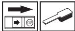
CAUTION! Some mufflers are fitted with a catalytic converter. See chapter on Technical data to see whether your machine is fitted with a catalytic converter.
The muffler is designed to reduce the noise level and to direct the exhaust gases away from the operator. The exhaust gases are hot and can contain sparks, which may cause fire if directed against dry and combustible material.
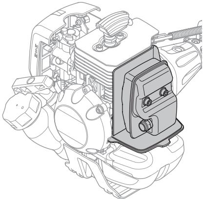
natural_image
Technical line drawing of an automotive engine assembly (no text or symbols visible)Some mufflers are equipped with a special spark arrestor mesh. If your machine has this type of muffler, you should clean the mesh at least once a week. This is best done with a wire brush. On mufflers without a catalytic converter the mesh should be cleaned weekly, or replaced if necessary. On mufflers fitted with a catalytic converter the mesh should be checked, and if necessary cleaned, monthly. If the mesh is damaged it should be replaced. If the mesh is frequently blocked, this can be a sign that the performance of the catalytic converter is impaired. Contact your dealer to inspect the muffler. A blocked mesh will cause the machine to overheat and result in damage to the cylinder and piston.
CAUTION! Never use a machine with a defective muffler.

WARNING! Mufflers fitted with catalytic converters get very hot during use and remain so for some time after stopping. This also applies at idle speed. Contact can result in burns to the skin. Remember the risk of fire!
Cooling system
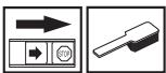
To keep the working temperature as low as possible the machine is equipped with a cooling system.
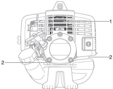
The cooling system consists of:
1 Cooling fins on the cylinder.
2 Air intake.
Clean the cooling system with a brush once a week, more often in demanding conditions. A dirty or blocked cooling system results in the machine overheating which causes damage to the piston and cylinder.
Air filter
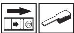
The air filter must be regularly cleaned to remove dust and dirt in order to avoid:
• Carburettor malfunctions
- Starting problems
- Loss of engine power
• Unnecessary wear to engine parts.
• Excessive fuel consumption.

natural_image
Technical line drawing of a mechanical assembly with internal components and housing (no text or symbols)Clean the filter every 25 hours, or more regularly if conditions are exceptionally dusty.
Cleaning the air filter
Remove the air filter cover and take out the filter. Wash it clean in warm, soapy water. Ensure that the filter is dry before refitting it.
An air filter that has been in use for a long time cannot be cleaned completely. The filter must therefore be replaced with a new one at regular intervals. A damaged air filter must always be replaced.
Fuel filter
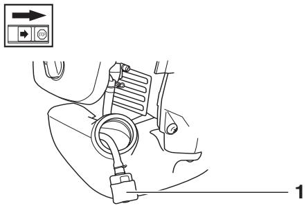
natural_image
Line drawing of a car seatbelt with a belt switch and directional control buttons (no text or symbols)1 Fuel filter
When the engine runs short of fuel supply, check the fuel cap and the fuel filter for blockage.
Bevel gear

The bevel gear is filled with the right quantity of grease at the factory. However, before using the machine you should check that the bevel gear is filled three-quarters full with grease. Use HUSQVARNA special grease.
The grease in the bevel gear does not normally need to be changed except if repairs are carried out.
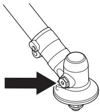
natural_image
Diagram of a mechanical joint or clamp mechanism with an arrow indicating direction (no text or symbols present)Spark plug

The spark plug condition is influenced by:
• Incorrect carburettor adjustment.
- An incorrect fuel mixture (too much or incorrect type of oil).
- A dirty air filter.
These factors cause deposits on the spark plug electrodes, which may result in operating problems and starting difficulties.
If the machine is low on power, difficult to start or runs poorly at idle speed: always check the spark plug first before taking any further action. If the spark plug is dirty, clean it and check that the electrode gap is 0,9-1,0 mm. The spark plug should be replaced after about a month in operation or earlier if necessary.
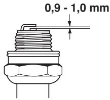
CAUTION! Always use the recommended spark plug type! Use of the wrong spark plug can damage the piston/cylinder. Check that the spark plug is fitted with a suppressor.
MAINTENANCE
Maintenance schedule
The following is a list of the maintenance that must be performed on the machine. Most of the items are described in the Maintenance section. The user must only carry out the maintenance and service work described in this Operator's Manual. More extensive work must be carried out by an authorised service workshop.
| Maintenance | Daily maintenance | Weekly maintenance | Monthly maintenance |
| Clean the outside of the machine. | X | ||
| Check that the harness is not damaged. | X | ||
| Make sure the throttle trigger lock and the throttle function correctly from a safety point of view. | X | ||
| Check that the handle and handlebar are undamaged and secured correctly. | X | ||
| Check that the stop switch works correctly. | X | ||
| Check that the cutting attachment does not rotate at idle. | X | ||
| Clean the air filter. Replace if necessary. | X | ||
| Check that the guard is undamaged and not cracked. Replace the guard if it has been exposed to impact or is cracked. | X | ||
| Check that the blade is correctly centred, is sharp, and is not cracked. An off-centre blade will cause vibration that could result in damage to the machine. | X | ||
| Check that the trimmer head is undamaged and not cracked. Replace the trimmer head if necessary. | X | ||
| Check that the locking nut of the cutting equipment is tighten correctly. | X | ||
| Check that the transport guard for the blade is intact and that it can be secured correctly. | X | ||
| Check that nuts and screws are tight. | X | ||
| Check that there are no fuel leaks from the engine, tank or fuel lines. | X | ||
| Check the starter and starter cord. | X | ||
| Check that the vibration damping elements are not damaged. | X | ||
| Clean the outside of the spark plug. Remove it and check the electrode gap. Adjust the gap to 0,6-0,7 mm or replace the spark plug. Check that the spark plug is fitted with a suppressor. | X | ||
| Clean the machine's cooling system. | X | ||
| Clean the outside of the carburettor and the space around it. | X | ||
| Check that the bevel gear is filled three-quarters full with lubricant. Fill if necessary using special grease. | X | ||
| Clean the muffler. | X | ||
| Check the fuel filter from contamination and the fuel hose from cracks or other defects. Replace if necessary. | X | ||
| Check all cables and connections. | X | ||
| Check the clutch, clutch springs and the clutch drum for wear. Replace if necessary by an autorized service workshop. | X | ||
| Replace the spark plug. Check that the spark plug is fitted with a suppressor. | X |
TECHNICAL DATA
Technical data
| 233RJ | |
| Engine | |
| Cylinder displacement, cm^3 | 29,5 |
| Cylinder bore, mm | 38,0 |
| Stroke, mm | 26 |
| Idle speed, rpm | 3000 |
| Recommended max. speed, rpm | 12000 |
| Speed of output shaft, rpm | 8220 |
| Max. engine output, acc. to ISO 8893 | 1,0/8000 |
| Catalytic converter muffler | No |
| Ignition system | |
| Manufacturer/type of ignition system | Ikeda Denso / Oppama |
| Spark plug | NGK CMR7H-10 |
| Electrode gap, mm | 0,9-1,0 |
| Fuel and lubrication system | |
| Manufacturer/type of carburettor | Walbro WYA |
| Fuel tank capacity, litre | 0,75 |
| Weight | |
| Weight without fuel, cutting attachment and guard, kg | 5,5 |
| Noise emissions(see note 1) | |
| Sound power level, measured dB(A) | 111 |
| Sound power level, guaranteed L_WA dB(A) | 112 |
| Noise levels(see note 2) | |
| Equivalent noise pressure level at the operator's ear,measured according to EN ISO 22868, dB(A), min./max.: | 94/98 |
| Vibration levels | |
| Vibration levels at handles, measured according toEN ISO 22867, m/s^2 | |
| At idle, left/right handles, min.: | 1,7/0,9 |
| At idle, left/right handles, max.: | 2,0/1,6 |
| At max. speed, left/right handles, min.: | 1,9/2,1 |
| At max. speed, left/right handles, max.: | 9,9/5,1 |
Note 1: Noise emissions in the environment measured as sound power ( L_WA ) in conformity with EC directive 2000/14/EC.
Note 2: Equivalent sound pressure level is calculated as the time-weighted energy total for sound pressure levels under various working conditions with the following time distribution: 1/2 idling and 1/2 max speed.
NOTE! The noise pressure level at operator's ear and vibrations on the handles are measured with all the approved cutting attachments for the machine. The table indicates the lowest and highest values.
TECHNICAL DATA
| Approved accessories | Type | Cutting attachment guard, Art. no. |
| Grass blade/grass cutter | Grass 255-4 (∅ 255 4 teeth) | 503 93 42-02 |
| Multi 255-3 (∅ 255 3 teeth) | 503 93 42-02 | |
| Plastic blades | Tricut ∅ 300 mm | 503 93 42-02 |
| Trimmer head | T25 | 503 97 71-01 / 503 93 42-02 |
| T35, T35x | 503 97 71-01 / 503 93 42-02 | |
| S35 | 503 97 71-01 / 503 93 42-02 | |
| Support cup | Fixed | - |
EC-declaration of conformity
(Applies to Europe only)
We, Husqvarna AB, SE-561 82 Huskvarna, Sweden, tel: +46-36-146500, declare that the clearing saws Husqvarna 233RJ with serial numbers dating from 2008 onwards (the year is clearly stated on the rating plate, followed by the serial number), comply with the requirements of the COUNCIL'S DIRECTIVE:
- of June 22, 1998 "relating to machinery" 98/37/EC, annex IIA.
- of December 15, 2004 "relating to electromagnetic compatibility" 2004/108/EC.
- of May 8, 2000 "relating to the noise emissions in the environment" 2000/14/EC. Conformity assessment according to Annex V. For information relating to noise emissions, see the chapter Technical data.
The following standards have been applied: EN ISO 12100-2, CISPR 12:2005, EN ISO 11806
SMP Svensk Maskinprovning AB, Fyrisborgsgatan 3, SE-754 50 Uppsala, Sweden, has carried out voluntary type approval for Husqvarna AB. The certificate has the number: SEC/09/1281
Huskvarna February 2, 2009

Michael Kullberg, Business manager
| Tri Cut | |||
| 1 | 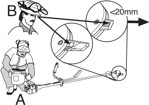 | 2 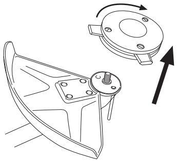 | |
| 3 | 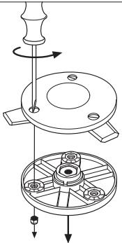 | 4 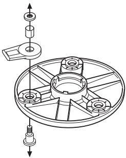 | 5 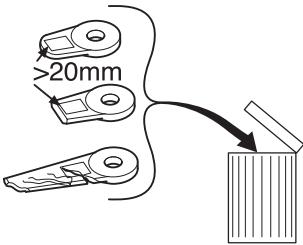 |
| 6 | 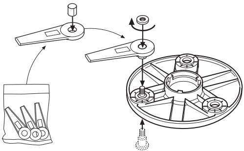 | 7 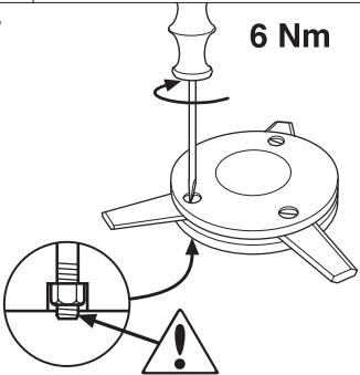 | |
| 8 | 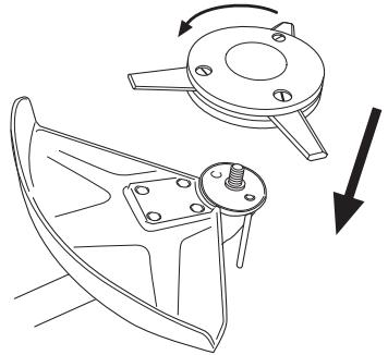 | 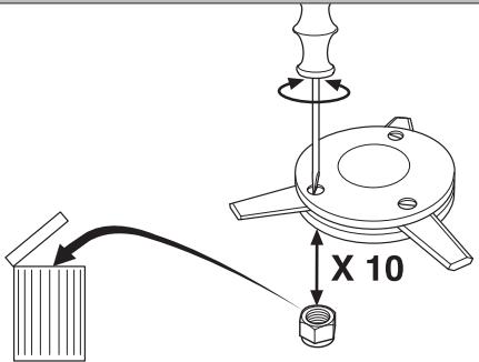 | |
| S35 | |||
1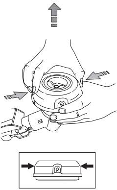 | 2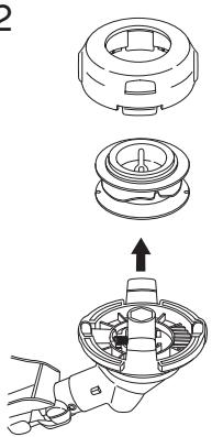 | 3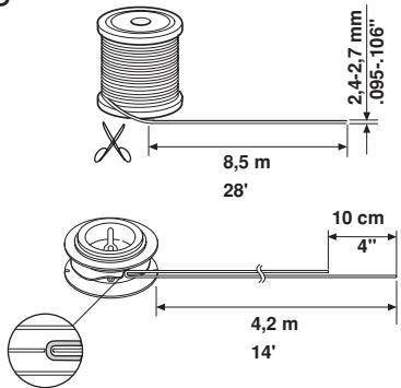 | |
4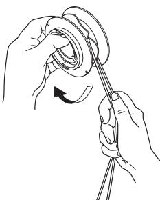 | 5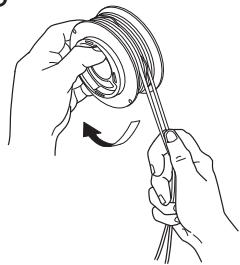 → → 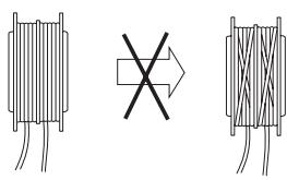 | ||
6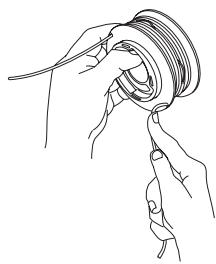 | 7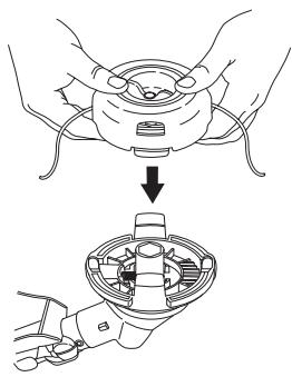 | 8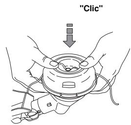 | |
1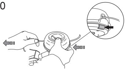 | 11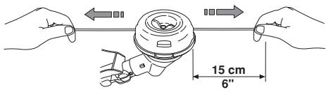 | ||
| S35 | ||
1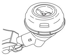 | 2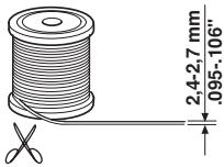 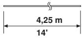 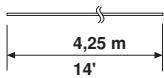 | |
3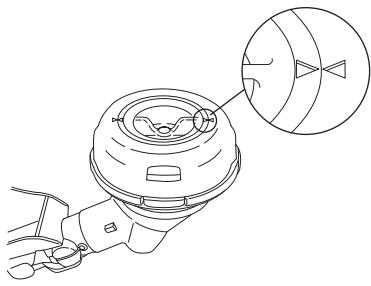 | 4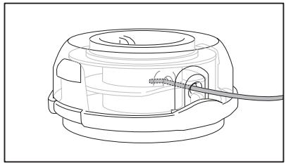 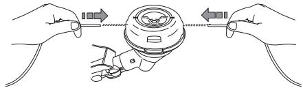 | |
5  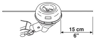 | ||
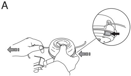 | B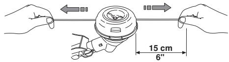 | |
| T35, T35x | |||
1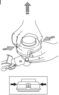 | 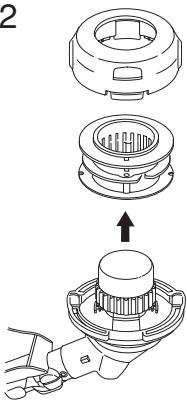 | 3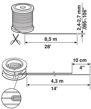 | |
4 | 5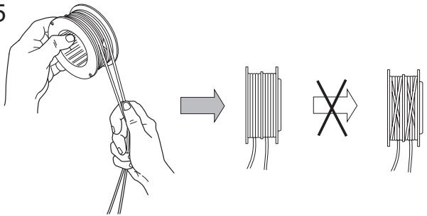 | ||
6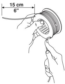 | 7 | 8 | |
9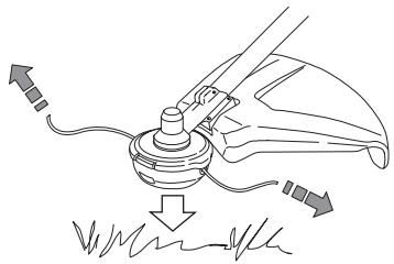 | |||
| T25 | |||
| 1 | 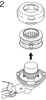 | 3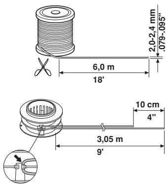 | |
4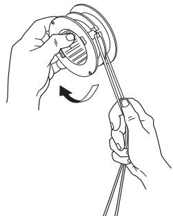 | 5 | ||
6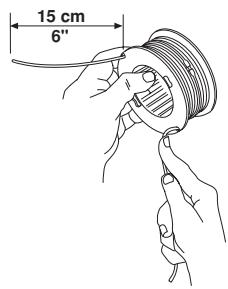 | 7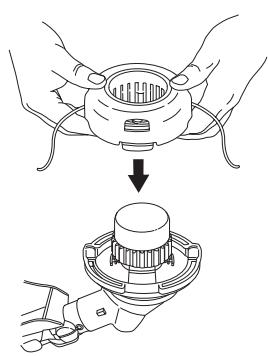 | 8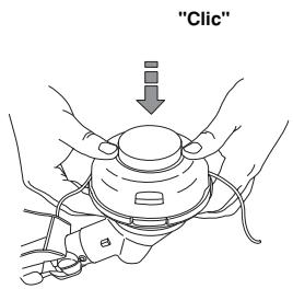 | |
9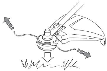 | |||
115 14 32-10