
CR 125 - Motorcycle HUSQVARNA - Free user manual and instructions
Find the device manual for free CR 125 HUSQVARNA in PDF.



| Product type | Competition motorcycle |
| Brand | HUSQVARNA |
| Model | CR 125 |
| Category | Motorcycle |
| Displacement | 124.82 cm³ |
| Engine type | Single-cylinder 2-stroke, liquid cooling |
| Bore x Stroke | 54 mm x 54.5 mm |
| Compression ratio | 8.8:1 |
| Carburetion | Mikuni TMX 38 carburetor (Ø 38 mm) |
| Ignition | Digital capacitive discharge electronic |
| Clutch | Multi-plate oil bath, mechanical control |
| Gearbox | 6-speed constant mesh |
| Secondary transmission | Chain, 13-tooth sprocket, 50-tooth sprocket |
| Front suspension | Telescopic hydraulic fork Ø 48 mm, adjustable |
| Rear suspension | Progressive hydraulic monoshock |
| Front brake | Wave disc Ø 260 mm, floating caliper |
| Rear brake | Wave disc Ø 240 mm, floating caliper |
| Tires | Front 80/100-21, rear 100/90-19 |
| Tire pressure (sport) | Front 0.9-1.0 kg/cm², rear 0.8-0.9 kg/cm² |
| Fuel tank | 7 L (including 1.5 L reserve) |
| Dry weight | 92 kg |
| Dimensions (L x W x H) | 2215 x 820 x 1305 mm |
| Seat height | 985 mm |
| Ground clearance | 325 mm |
| Engine oil (mixture) | 3-4% oil in gasoline (Castrol A747) |
| Gearbox oil | Castrol Power 1 Racing 10W-40 (0.8 L) |
| Cooling | Liquid (Castrol Motorcycle Coolant, 1.1-1.3 L) |
| Spark plug | NGK BR9EG or Champion QN84, gap 0.6 mm |
| Starting | Kick starter |
Frequently Asked Questions - CR 125 HUSQVARNA
User questions about CR 125 HUSQVARNA
0 question about this device. Answer the ones you know or ask your own.
Ask a new question about this device
Download the instructions for your Motorcycle in PDF format for free! Find your manual CR 125 - HUSQVARNA and take your electronic device back in hand. On this page are published all the documents necessary for the use of your device. CR 125 by HUSQVARNA.
USER MANUAL CR 125 HUSQVARNA
To the best knowledge of HUSQVARNA MOTORCYCLES S.R.L. the material contained herein is accurate as of the date this publication was approved for printing. HUSQVARNA MOTORCYCLES S.R.L. reserves the right to change specifications, equipment, or designs at any time without notice and without incurring obligation. Illustrations in this manual are merely for demonstration purposes and could not exactly match the detail described. No part of this manual can be reproduced without permission in writing of the copyright holder.
1 ^st Edition (06-09)
natural_image
Black and white photo of a CR 125 motorcycle with visible tracks, wheels, and engine components (no text or symbols on the bike body)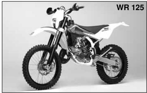
natural_image
Side view of a white and black off-road motorcycle with visible dynamics and wheels (no text or symbols)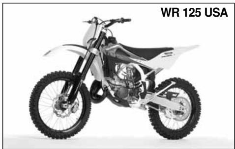
natural_image
Black and white photo of a Driton motorcycle with visible wheels and engine components (no text or symbols on the bike body)
natural_image
Stylized black-and-white graphic of a stylized 'H' within a rounded rectangular shape (no text or symbols)CR 125 2010
WR 125 2010
WR 125 2010 USA (EN)
Unless specified, data and prescription are referred to all the models.
natural_image
Side profile of a white and black off-road motorcycle with visible tracks and wheels (no text or symbols)
natural_image
Side profile of a white and black off-road motorcycle with visible tracks and wheels (no text or symbols)MOTOCROSS
natural_image
Black-and-white photo of a motorcyclist mid-jump, wearing helmet and gear (no visible text or symbols)ENDURO
natural_image
Black-and-white photo of a dirter mid-jump on a motorcycle in a mountainous field (no visible text or symbols)IMPORTANTE
DATI TECNICI
MOTORE
Getto minimo (WR)....15
Getto starter (CR) 80
Getto starter (WR) 50
Valvola gas (CR)....4,0
Valvola gas (WR) 5,0
Spillo conico 6BFY43
Dunlop D756; 80/100x21"
Anteriore (WR)....Michelin ENDURO COMP. 3 oppure
Pirelli MT 83 Scorpion; 90/90x21"
Posteriore (CR) ..... Pirelli NH5 (57) MT 32 oppure
Dunlop D756; 100/90x19"
Posteriore (WR).... Michelin ENDURO COMP. 3 oppure
Pirelli MT 83 Scorpion; 120/90x18"
(posteriore) (%) 1,0 Kg/cm2
CARBURANTE
natural_image
Close-up of a mechanical component with labeled parts (no readable text or symbols)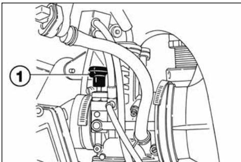
natural_image
Mechanical assembly diagram showing hoses and components (no text or labels)STRUMENTO DIGITALE, SPIE (WR)
2- SPEED / CLOCK (figura 2)
COMANDO GAS
natural_image
Close-up of a car engine component with visible wiring and a numbered label (1), no readable text or symbols present.COMMUTATORE SINISTRO SUL MANUBRIO (WR)
PULSANTE ARRESTO MOTORE (CR)
natural_image
Technical line drawing of a mechanical component with labeled part (1), no readable text or symbols present.
AVVERTENZA
natural_image
Mechanical assembly diagram showing a motor and linkage mechanism (no text or symbols visible)COMANDO CAMBIO
natural_image
Mechanical assembly diagram showing gear and components without any text or symbolsISTRUZIONI PER L'USO DEL MOTOCICLO
CONTROLLI PRELIMINARI
ATTENZIONE!
natural_image
Technical line drawing of a mechanical assembly with no visible text or symbols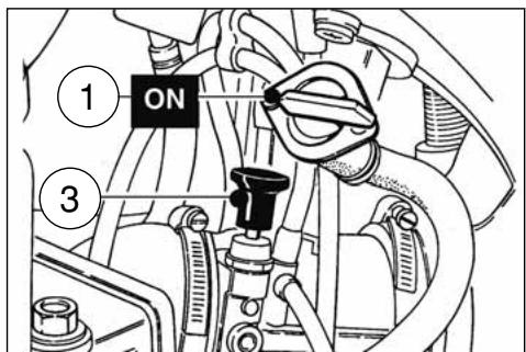
natural_image
Mechanical assembly diagram showing gear and shaft components (no text or labels)ARRESTO DEL MOTOCICLO E DEL MOTORE
natural_image
Technical line drawing of a mechanical assembly with no visible text or symbols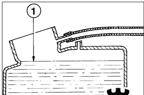
CONTROLLO CANDELA
natural_image
Technical line drawing of a spark plug with threaded end and shaft (no text or symbols)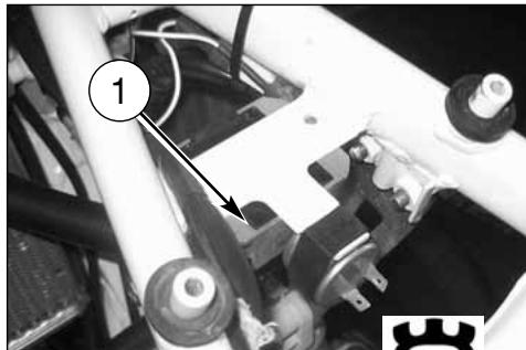
natural_image
Close-up of mechanical components with numbered annotation (1) and a gear icon, no readable text or symbols present.CONTROLLO FILTRO ARIA
natural_image
Side view of a black-and-white photo of a motorcycle's front wheel and side gear (no text or symbols visible)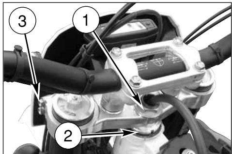
REGOLAZIONE LEVA COMANDO E CONTROLLO LIVELLO FLUIDO FRENO ANTERIORE
natural_image
Mechanical assembly diagram showing a bracket with labeled component A (no text or symbols beyond label)natural_image
Black-and-white photo of a motorcyclist riding a dirt bike across a dusty terrain under cloudy skies (no text or symbols visible)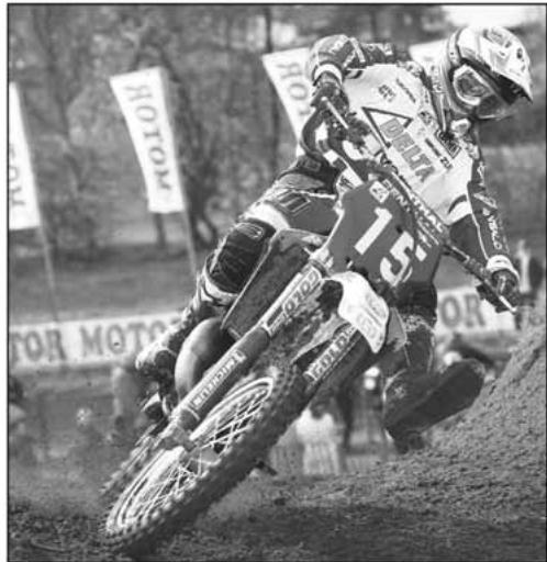
natural_image
Black-and-white photo of a dirter in action on a dirt track, wearing helmet and racing gear, with 'ROTOM' banners visible in background (no readable text on rider or equipment)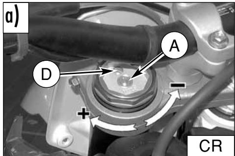
LIVELLO OLIO FORCELLA
REGISTRAZIONE AMMORTIZZATORE
natural_image
Diagram of a mechanical component with a circular ring and labeled part 1 (no text or symbols beyond label)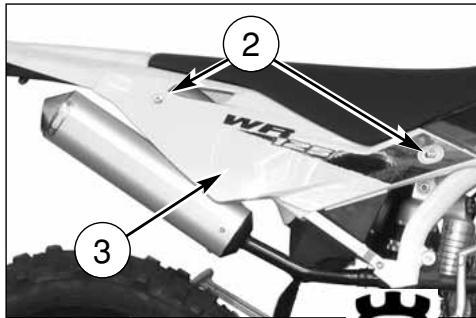
natural_image
Mechanical assembly diagram showing linkage components with arrows indicating motion (no text or symbols)REGISTRAZIONE CATENA (Fig. A)
CONTROLLO USURA CATENA, PIGNONE, CORONA
natural_image
Close-up of a black-and-white photo of a motor with visible wheel, suspension, and gear mechanism (no text or symbols)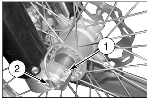
RIMONTAGGIO RUOTA ANTERIORE
natural_image
Close-up of a motorcycle's front wheel and suspension system (no visible text or symbols)SMONTAGGIO RUOTA POSTERIORE
PNEUMATICI
natural_image
Top-down view of a bicycle wheel with visible tire, disc, and hub (no text or symbols)FRENI
natural_image
Technical line drawing of a mechanical gauge or dial mounted on a structural frame (no text or symbols visible)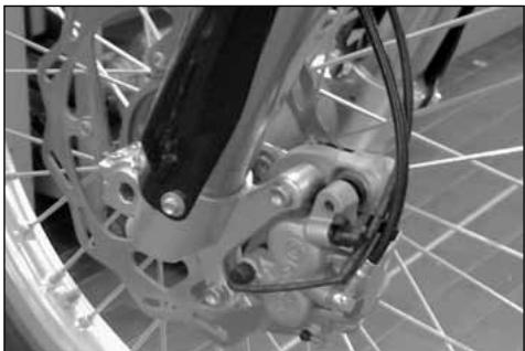
natural_image
Close-up of a bicycle's front wheel and brake system (no visible text or symbols)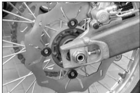
natural_image
Close-up of a bicycle wheel assembly with visible brake calipers and suspension components (no text or symbols)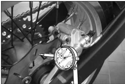
natural_image
Close-up of a mechanical assembly with a dial indicator and brake caliper (no visible text or symbols)PULIZIA DISCO
natural_image
Close-up of a bicycle wheel's head and dashboard assembly (no visible text or symbols)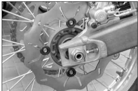
natural_image
Close-up of a bicycle brake system with visible components and wheel rim (no text or symbols)SOSTITUZIONE FLUIDO
natural_image
Close-up of a bicycle wheel assembly with visible mechanical components and a numbered annotation (1) pointing to a specific part.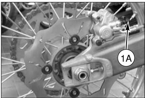
natural_image
Close-up of a bicycle wheel assembly with visible gears and brake calipers (no text or symbols)AVVERTENZA!
natural_image
Side-by-side comparison of a bicycle wheel and its internal mechanical components (no text or symbols visible)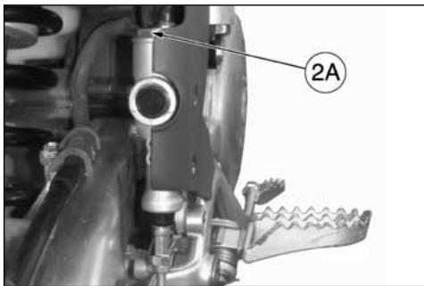
natural_image
Technical line drawing of a mechanical tool with handle and lever (no text or symbols)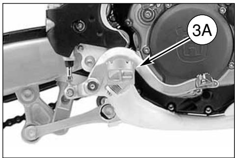
natural_image
Close-up mechanical assembly showing a gear mechanism and labeled component 3A (no readable text or symbols beyond label)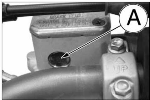
natural_image
Mechanical assembly diagram showing a gear and shaft assembly (no text or symbols visible)ATTENZIONE!
natural_image
Close-up of a bicycle wheel with visible tire, brake caliper, and mechanical components (no text or symbols)SPURGO IMPIANTO FRENANTE ANTERIORE
natural_image
Close-up of a bicycle wheel assembly with visible mechanical components and a numbered annotation (1) pointing to a specific part.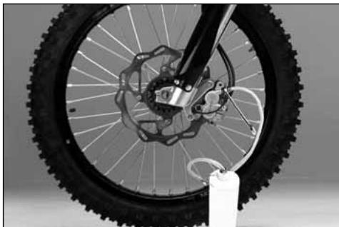
natural_image
Close-up of a bicycle wheel with visible tire, disc brake, and hub assembly (no text or symbols)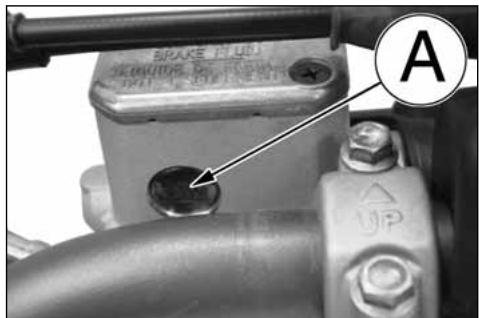
SPURGO IMPIANTO FRENANTE POSTERIORE
natural_image
Mechanical assembly diagram showing a valve and gear mechanism (no text or symbols)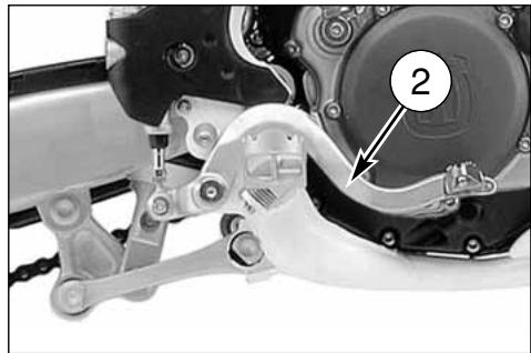
natural_image
Mechanical assembly diagram showing a motor and gear mechanism with labeled component (no readable text or symbols)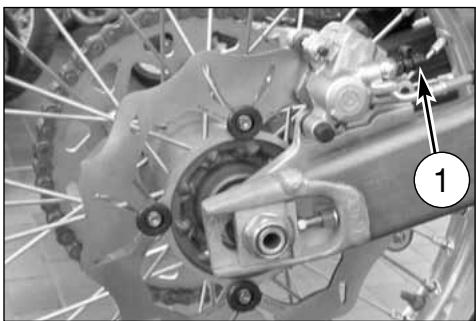
natural_image
Close-up of a bicycle brake system with visible components and a numbered label (1), no readable text or symbols present.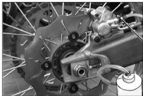
natural_image
Close-up of a bicycle brake system with visible components and suspension rings (no text or symbols)ATTENZIONE!
natural_image
Mechanical assembly diagram showing a valve or pump component with labeled part B (no text or symbols beyond label)SILENZIATORE DI SCARICO
REVISIONE RUOTE
natural_image
Technical line drawing of a mechanical device with dual gauges and adjustment knobs (no text or symbols)PIEGATURA PERNO RUOTA
natural_image
Technical line drawing of a pressure gauge mounted on a mechanical component (no text or symbols)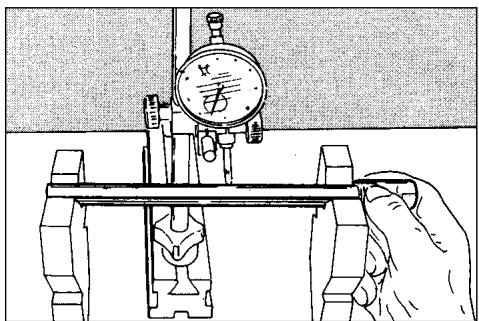
natural_image
Illustration of a hand operating a mechanical testing setup with a dial and clamped components (no text or symbols)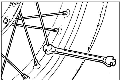
natural_image
Mechanical linkage diagram showing a bone and connecting rods (no text or labels)natural_image
Close-up of a mechanical assembly with a circular component and wiring, no visible text or symbols
natural_image
Mechanical assembly diagram showing components labeled 4 and 7, with no readable text or symbols beyond labels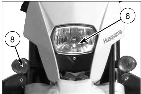
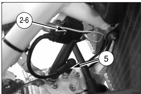
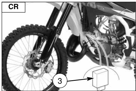
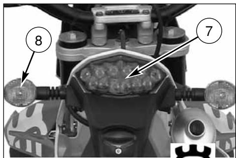
LEGENDA COLORE CAVI (WR)
natural_image
Top-down view of a motorcycle's front wheel and dashboard (no visible text or symbols)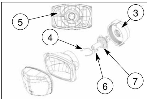
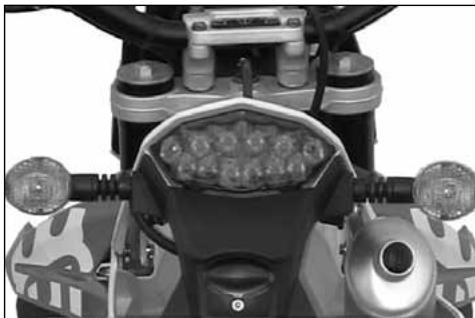
SOSTITUZIONE LAMPADA LUCE TARGA (WR)
natural_image
Close-up of a mechanical component with a numbered annotation (4) pointing to a small feature, no readable text or symbols present.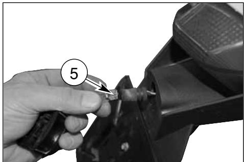
natural_image
Close-up of a hand using a tool to cut a mechanical component, no visible text or symbolsREGISTRAZIONE FANALE ANTERIORE (WR)
natural_image
Close-up of a white off-road vehicle's rear suspension system with visible tire tracks and mechanical components (no text or symbols)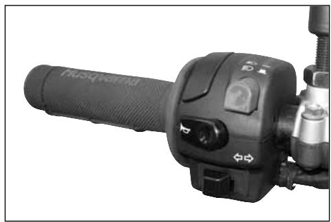
natural_image
Close-up of a black automotive hand crank with control buttons and lever (no visible text or symbols)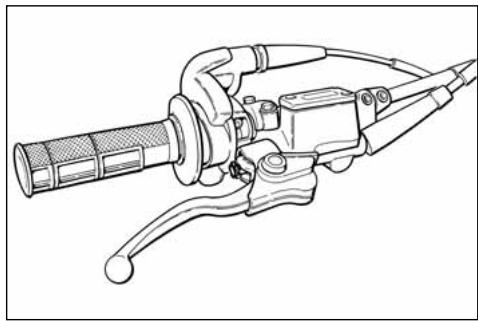
natural_image
Line drawing of a mechanical tool with handle and lever (no text or symbols)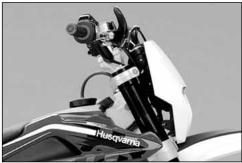
natural_image
Close-up of a motorcycle's front view showing the Husqvarna brand emblem (no text or symbols on the body itself)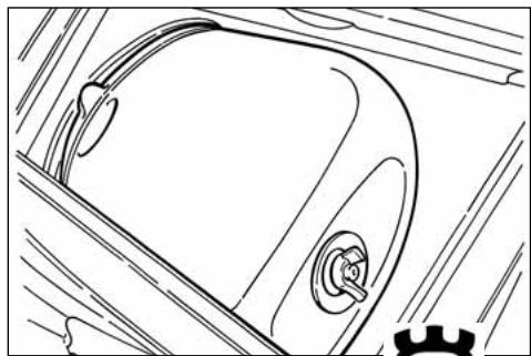
natural_image
Line drawing of a car's front wheel and side door (no text or symbols)natural_image
Close-up of a bicycle's front wheel and brake system with visible springs and hub (no text or symbols)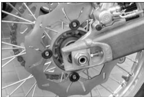
natural_image
Close-up of a bicycle brake system with visible components and wheel rim (no text or symbols)Welcome to the Husqvarna motorcycling Family!
Your new Husqvarna motorcycle is designed and manufactured to be the finest in its field.
The instructions in this book have been prepared to provide a simple and understandable guide for your motorcycle's operation and care.
Follow the instructions carefully to obtain maximum performance and your personal motorcycling pleasure. Your owner's manual contains instructions for owner care and maintenance.
The main work of repair or maintenance requires the attention of a skilled mechanic and the use of special tools and equipment.
Your Husqvarna dealer has the facilities, experience and original parts necessary to properly render this valuable service.
This "Owner's Manual" is part and parcel of the motorcycle, hence, this had to remain with the motorcycle even when sold to another user.
This motorcycle uses components designed thanks to systems and state of the art technologies which are thereafter tested in competition.
In competition motorcycles, every detail is verified after each race in order to always guarantee better performance. For correct functioning of the vehicle, it is necessary to follow the maintenance and control table found on Appendix A.
IMPORTANT NOTICES
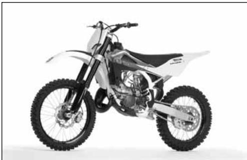
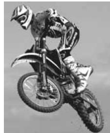
1) The CR models are guaranteed COMPE-TITION motorcycles exempt from functional defects, the suggested maintenance table for competition use is shown on Appendix A.
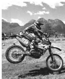
2) WR vehicles are STREET LEGAL motorcycles (with LIMITED POWER ENGINE); they are guaranteed exempt from functional defects and covered with legal guarantee, if the STANDARD CONFIGURATION is maintained and the suggested maintenance table, shown on Appendix A (page A8) is observed. If WR vehicles are transformed in COMPE-TITION MOTORCYCLES (with FULL POWER ENGINE), the suggested maintenance table for competition use is shown on Appendix A.
natural_image
Side profile of a white and black off-road motorcycle with visible tracks and wheels (no text or symbols)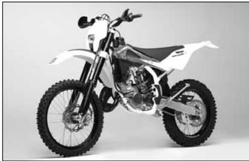
natural_image
Side profile of a white and black off-road motorcycle with visible tracks and wheels (no text or symbols)MOTOCROSS
natural_image
Black-and-white photo of a motorcyclist mid-jump, wearing helmet and gear (no visible text or symbols)ENDURO
natural_image
Black-and-white photo of a dirter mid-jump on a motorcycle in a mountainous outdoor field (no visible text or symbols)IMPORTANT
The reference for recognition of the guarantee will be the MOTORCYCLE CONFIGURATION, as shown below:
A) STANDARD MOTORCYCLE, STREET LEGAL: with LIMITED POWER ENGINE
B) COMPETITION MOTORCYCLE, RACING USE: with FULL POWER ENGINE
This motorcycles was not designed for long trips with the engine always at maximum rpm as can occur whilst travelling on roads or highways. Long trips at full throttle can cause severe damage to the engine. This motorcycles is setup for competition use and therefore guarantees maximum performance with the rider alone. It is thereby not recommended to use the vehicle on circuits or off-road with a passenger.
ALWAYS keep in mind that these motorcycles have been designed strictly for competition use, that is, for conditions of usage very different from those presented on the road.
ALWAYS keep in mind that these motorcycles have been designed strictly for competition use, that is, for conditions of usage very different from those presented on the road.
In order to maintain the vehicle's "Guarantee of Functionality", the client must follow the maintenance program indicated in the user's manual by carrying out maintenance checks at authorized HUSQVARNA dealers. The cost for substitut-
ing parts and for the labour necessary in order to respect the maintenance plan, is charged to the client.
NOTE: the guarantee is EXTINGUISHED in the case where the motorcycle is rented.
Important Notice
Read this manual carefully and pay special attention to statements preceded by the following words:
Warning*: Indicates a possibility of severe personal injury or loss of life if instructions are not followed.
Caution*: Indicates a possibility of personal injury or equipment damage if instructions are not followed.
Note*: Gives helpful information.
Parts Replacement
When parts replacement is required, use only Husqvarna ORIGINAL parts.
Warning*: After an upset, inspect the motorcycle carefully. Make sure that the throttle, brake, clutch and all other systems are undamaged. Riding with a damaged motorcycle can lead to a serious crash.
Warning*: Never attempt to start or operate your motorcycle unless you are wearing appropriate protective clothing. Always wear a motorcycle helmet, motorcycle boots, gloves, goggles and other appropriate protective clothing.
Warning*: This motorcycle is a state of the art competition bike. Do not attempt to start or ride this motorcycle until you have received expert instruction and are in excellent physical condition.
PRECAUTIONS FOR CHILDREN WARNING
- Park the vehicle where it is unlikely to be bumped into or damaged. Even slight or involuntary bumps can cause the vehicle to topple over, with subsequent risk of serious harm to people or children.
- To prevent the vehicle from tipping over, never park it on soft or uneven ground, nor on asphalt strongly heated by the sun.
- Engine and exhaust pipes become very hot during riding. Always park your motorcycle where people or children can not easily reach these parts, in order to avoid serious burns.
TABLE OF CONTENTS Page
PRESENTATION 2
IMPORTANT NOTICES 2
IDENTIFICATION DATA....5
TECHNICAL DATA 7
LUBRICATION TABLE, SUPPLIES 8
CONTROLS....9
RIDING....12
IGNITION SYSTEM/ELETTRICAL SYSTEM....51-55
EQUIPMENT....56
OPTIONAL PARTS LIST....57
APPENDIX 58
PRE-DELIVERY INSPECTION 61
ALPHABETICAL INDEX......62
PERIODIC MAINTENANCE -ADJUSTMENT ......Appendix A
Note
- References to the "left" or "right" of the motorcycle are in the sense of a person facing forwards.
• Z: number of teeth
• A: Austria
AUS: Australia
B: Belgium
BR: Brazil
CDN: Canada
CH: Switzerland
D: Germany
E: Spain
F: France
FIN: Finland
GB: Great Britain
I: Italy
J: Japan
USA: United States of America
- Where not specified, all the data and the instructions are referred to any and all Countries.
IDENTIFICATION DATA
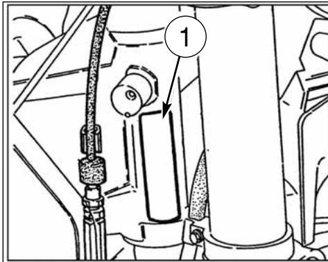
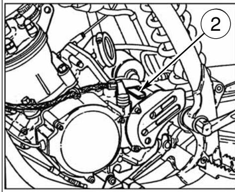
The engine number is printed on the upper side of the engine case, whereas the frame number is printed on the steering tube. Always state the number stamped on the frame (and write it on this booklet), when placing orders for spare parts, or when asking for informations about your motorcycle.
FRAME NUMBER
VEHICLE IDENTIFICATION NUMBER (V.I.N.)
The full 17 digit serial, or Vehicle Identification Number, is stamped on the steering head tube (R.H. side).
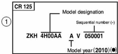
flowchart
graph TD
    A["CR 125"] --> B["Model designation"]
    B --> C["ZKH 4H00AA"]
    B --> D["A V 050001"]
    B --> E["Sequential number (+)"]
    B --> F["Model year (2010) (●)"]
(*): Progressiv nr.
(•): Year of the model
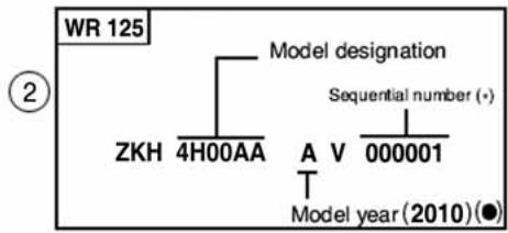
flowchart
graph TD
    A["WR 125"] --> B["Model designation"]
    B --> C["ZKH 4H00AA"]
    B --> D["A V 000001"]
    B --> E["Sequential number (+)"]
    B --> F["Model year (2010) (●)"]
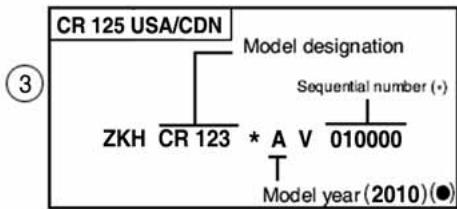
flowchart
graph TD
    A["CR 125 USA/CDN"] --> B["ZKH CR 123"]
    A --> C["Model designation"]
    C --> D["* A V 010000"]
    C --> E["Sequential number (+)"]
    C --> F["Model year (2010) (●)"]
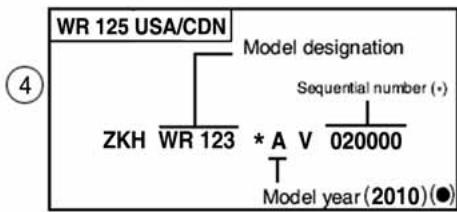
flowchart
graph TD
    A["WR 125 USA/CDN"] --> B["ZKH WR 123"]
    A --> C["Model designation"]
    C --> D["* A V 020000"]
    C --> E["Sequential number (•)"]
    C --> F["Model year (2010) (●)"]
-
Frame serial number
-
Engine serial number
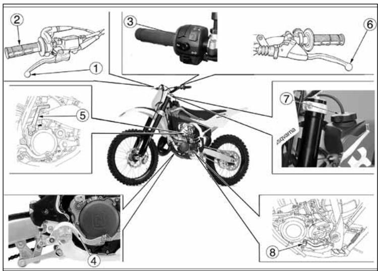
CONTROL LOCATION
- Front brake lever
- Throttle grip
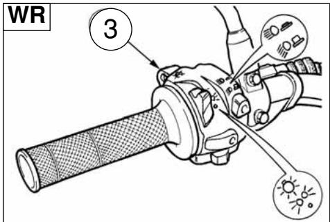
3- L.H. commutator (WR) - Rear brake control pedal
- Starting pedal
- Clutch control lever
- Fuel tank filler cap
- Gearbox control pedal
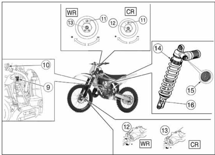
-
Choke (L.H. side)
-
Fuel cock
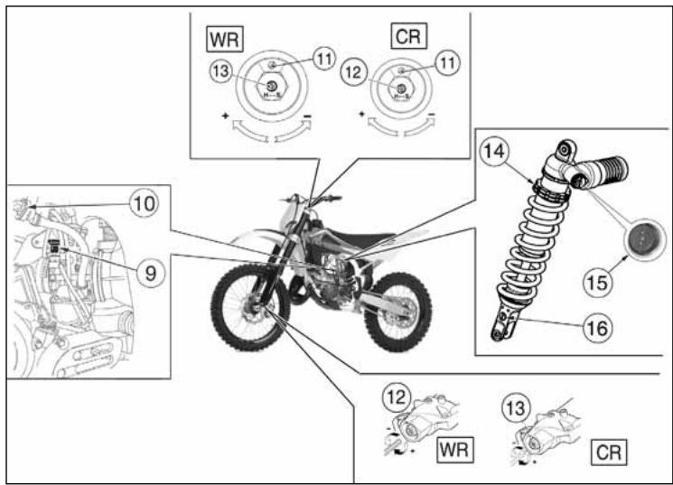
- Air bleeding screw on front fork leg
- Compression damper adjustment (front fork leg)
- Extension damper adjustment (front fork leg)
14 .Rear shock absorber spring preload adjustment - Rear shock absorber compression damper adjustment (low and high damping speeds)
- Rear shock absorber extension damper adjustment
TECHNICAL DATA
ENGINE
Type.....single cylinder, 2 stroke
Cooling.....liquid
Bore 2.13 in.
Stroke 2.15 in.
Displacement 7.62 cu. in.
Compression ratio
(with closed ports)....8,8:1
Starting ......kick start
TIMING SYSTEM
Type.....lamellar valve on suction in the crankcase and H.T.S. valve with mechanical control on the exhaust
LUBRICATION
Engine 4% (1:25) of oil-gasoline mix during running in; NOT LESS than 3% (1:33) when running in is over
Primary drive transmission/Gearbox .. by the oil contained in the crankcase
IGNITION
Type..... electronic analogic (WR) or digital (CR) capacitor-discharge type, with variable advance
Spark plug type.... CHAMPION QN B4/NGK BR9EG Gap.... 0.0236 in.
FUEL SYSTEM
Venturi diameter 1.5 in.
High speed jet (CR) 460
High speed jet (WR) 380
Low speed jet (CR) 35
Low speed jet (WR) 15
Starting jet (CR) 80
Starting jet (WR) 50
Main nozzle R-8 (914)
Throttle piston (CR)....4,0
Throttle piston (WR) 5,0
Metering pin....6BFY43
Metering pin slot (CR)....3rd
Metering pin slot (WR) 2nd
Idle mixture adjusting screw (CR) ......rounds 1+1/4
Idle mixture adjusting screw(WR).....rounds 1+1/2
PRIMARY DRIVE
Drive pinion gear- Clutch ring gear ....Z 22-Z 71
Transmission ratio 3,227
CLUTCH
Type....oil bath multiple disc clutch, mechanical control
TRANSMISSION
Type......constant mesh gear type
Transmission ratio
3rd gear....1,579 (Z 30/19)
4th gear....1,350 (Z 24/22)
5th gear....1,181 (Z 26/22)
6th gear....1,000 (Z 21/21)
SECONDARY DRIVE
Transmission sprocket- Rear wheel sprocket ....Z 13-Z 50
Transmission ratio 3,846
FINAL RATIOS
1st gear 29,258
2nd gear....23,170
3rd gear 19,599
4th gear 16,757
5th gear 14,669
6th gear 12,412
FRAME
Type....Steel single tube cradle (roud tubes); light alloy rear frame.
FRONT SUSPENSION
Type......"Upside-down" telescopic hydraulic front fork with advanced axle (adjustable in compression and rebound stroke); stanchions tubes ∅ 1.89 in.
Legs axis stroke....11.8 in.
REAR SUSPENSION
Type ....progressive with hydraulic single shock absorber Wheel stroke....11.6 in.
FRONT BRAKE
Type fixed disc ∅ 10.24 in. "Wave" type with hydraulic control and floating caliper
REAR BRAKE
Type ....floating disc, ∅ 9.45 in. "Wave" type
with hydraulic control and floating caliper
RIMS
Front ....TAKASAGO "Excel" in light alloy: 1,6x21"
Rear (CR)....TAKASAGO "Excel" in light alloy: 2,15x19"
Rear (WR)....TAKASAGO "Excel" in light alloy: 2,15x18"
TYRES
Front (CR)....Pirelli 51R-MT32A or
Dunlop D756; 80/100x21"
Front (WR) .... Michelin ENDURO COMP. 3 or
Pirelli MT 83 Scorpion; 90/90x21"
Rear (CR).... Pirelli NH5 (57) MT 32 or
Dunlop D756; 100/90x19"
Rear (WR) .... Michelin ENDURO COMP. 3 or
Pirelli MT 83 Scorpion; 120/90x18"
Cold tire pressure
(front) (*) 12.8÷14.2 psi
(front) (%).... 15.6 psi
rider and passenger
(rear) (*) 11.4÷12.8 psi
(rear) (%).... 14.2 psi
(*) Racing use - (%) Road use
DIMENSION, WEIGHT, CAPACITY
Wheelbase (CR) 57.48 in.
Wheelbase (WR) 57.68 in.
Overall length(CR)......87.2 in.
Overall length (WR) 88.98 in.
Overall width (CR)....32.28 in.
Overall width (WR)....33.07 in.
Overall height (CR) 51.38 in.
Overall height (WR) 51.18 in.
Saddle height (CR)....38.78 in.
Saddle height (WR) 38.38 in.
Minimum ground clearance (CR) 12.79 in.
Minimum ground clearance (WR) 12.4 in.
Kerb weight, without fuel(CR) 202.8 lb
Kerb weight, without fuel(WR) 211.6 lb
Kerb weight, without fuel(WR USA/CDN) ..... 206.8 lb
Fuel tank capacity, (1.32 Imp. quarts, 1.59 U.S. quart reserve
included) 1.54 Imp. gall., 1.85 U.S. gall.
Coolant capacity....0.97÷1.14 Imp. Quarts, ....1.16÷1.37 U.S. Quarts
Transmission oil.....0.70 Imp. Quarts, 0.85 U.S. Quarts
| TABLE FOR LUBRICATION, SUPPLIES |
| Engine lubricating oilCASTROL A747 |
| Gearbox and primary drive lubricating oilCASTROL POWER 1 RACING 10W-40 |
| Engine coolantCASTROL MOTORCYCLE COOLANT |
| Brake system fluidCASTROL RESPONSE SUPER DOT 4 |
| Grease lubricationCASTROL LM GREASE 2 |
| Final drive chain lubricationCASTROL CHAIN LUBE RACING |
| Front fork oilKHL15-11 |
| Oil for rear shock absorberCASTROL SYNTHETIC FORK OIL 5W |
| Electric contact protectionCASTROL METAL PARTS CLEANER |
| Fillers for radiatorAREXONS TURAFALLE LIQUIDO |
CONTROLS
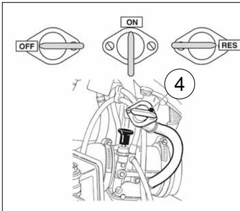
FUEL COCK
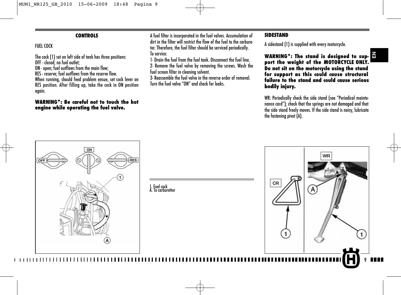
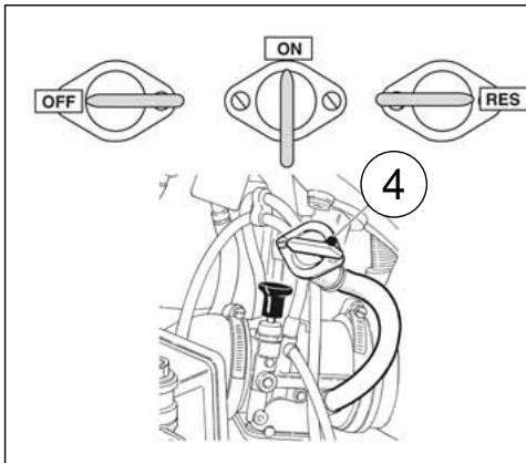
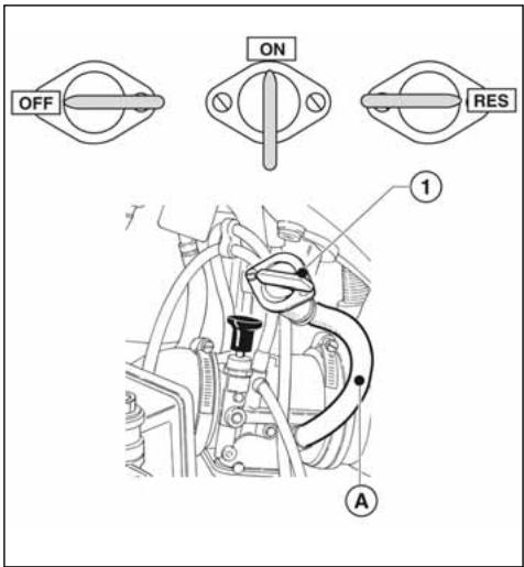
The cock (1) set on left side of tank has three positions:
OFF - closed; no fuel outlet;
ON - open; fuel outflows from the main flow;
RES - reserve; fuel outflows from the reserve flow.
When running, should feed problem ensue, set cock lever on RES position. After filling up, take the cock in ON position again.
WARNING\*: Be careful not to touch the hot engine while operating the fuel valve.
A fuel filter is incorporated in the fuel valves. Accumulation of dirt in the filter will restrict the flow of the fuel to the carburetor. Therefore, the fuel filter should be serviced periodically. To service:
1- Drain the fuel from the fuel tank. Disconnect the fuel line.
2- Remove the fuel valve by removing the screws. Wash the fuel screen filter in cleaning solvent.
3- Reassemble the fuel valve in the reverse order of removal. Turn the fuel valve "ON" and check for leaks.
SIDESTAND
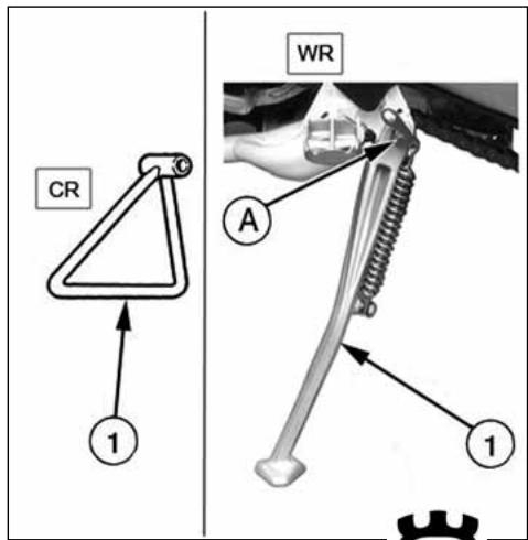
A sidestand (1) is supplied with every motorcycle.
WARNING*: The stand is designed to support the weight of the MOTORCYCLE ONLY. Do not sit on the motorcycle using the stand for support as this could cause structural failure to the stand and could cause serious bodily injury.
WR: Periodically check the side stand (see "Periodical maintenance card"); check that the springs are not damaged and that the side stand freely moves. If the side stand is noisy, lubricate the fastening pivot (A).
- Euel cock A. To carburettor
FUEL
The motorcycle is equipped with 2 stroke engine that requires a gasoline-oil mixture. Recommended fuel: premium grade unleaded fuel (R.O.N. 98).
Note*: Do not continue operation if the engine pings or knocks. The engine will be damaged and could seize.
WARNING*: If "knocking" or "pinging" occurs, try a different brand of gasoline or higher octane grade.
WARNING*: Gasoline is extremely flammable and can be explosive under certain conditions. Always stop the engine and do not smoke or allow flames or sparks in the area where the motorcycle is refueled or gasoline is stored.
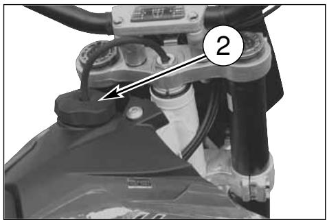
WARNING*: Do not overfill the tank. After refueling, make sure the tank cap (2) is closed securely.
CARBURETOR CHOKE
The starter knob (1), located on the left side of the carburetor, is used to enrich the mixture during the engine start. Pull out the knob to open the starter, and pull the lever upwards to close it.
natural_image
Close-up of a mechanical component with labeled parts (no readable text or symbols)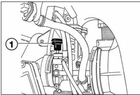
natural_image
Mechanical assembly diagram showing hoses and components (no text or labels)DIGITAL INSTRUMENT, WARNING LIGHTS (WR)
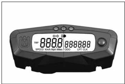
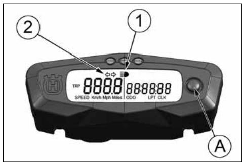
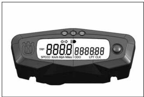
The motorcycle is equipped with a digital instrument; on the instrument are located 2 warning lights too: high beam and blinkers.
1- BLUE warning light "HIGH BEAM"
2- GREEN warning light "BLINKERS"
The instrument display illuminates (amber colour) when the engine started.
NOTES
- Every time the engine starts, for the first 2 seconds, the instrument shows the version of the checking SW; after the check, the instrument shows the last planned function.
- When the motorcycle engine is OFF, the instrument doesn't also show its functions.
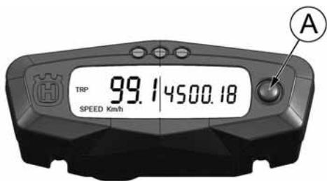
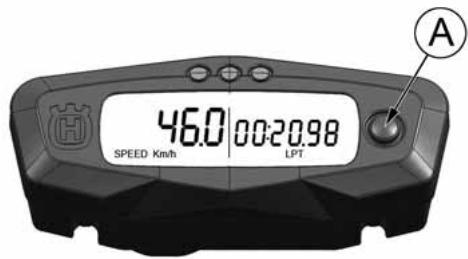
- To select the instrument functions and to set to zero the functions, use the SCROLL knob (A).
- The instrument functions are the following, as shown below.
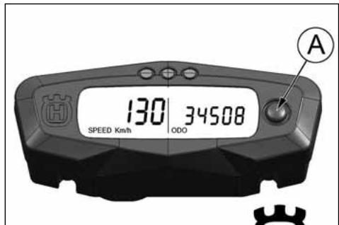
1- SPEED / ODO (figure 1)
2- SPEED / CLOCK (figure 2, page 13)
3- SPEED / TRIP (figure 3, page 13)
4- SPEED / CHRONO (figure 4, page 13)
1- SPEED / ODO (figure 1)
......
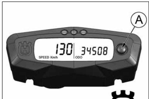
1- SPEED (Km/h or mph) / ODO (figure 1)
- SPEED: motorcycle speed- maximum value: 299 Km/h or 299 mph;
- ODO: odometer- maximum value: 99999 km;
To replace kilometers with miles or miles with kilometers proceed as follows:
1) set to figure 1, stop the engine and push the knob SCROLL (A);
2) Start the engine holding pushed the button SCROLL (A) until the symbol "Km/h" will be displayed;
3) then the symbols "Km/h" and "Mph Miles" will be displayed alternatively. Push again the SCROLL (A) button when the unit you wish to use is displayed.
2- SPEED / CLOCK (figure 2)
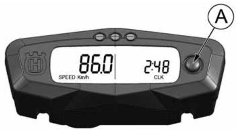
- SPEED: motorcycle speedmaximum value: 299 Km/h o 299 mph;
- CLOCK: clock- Reading from 0:00 to 23:59:59; To reset the clock, push the knob SCROLL (A) for more than 3 seconds in order to increase the hours; release the knob and then, after 3 seconds, it is possible to increase the minutes;
3- SPEED / TRIP 1 (figure 3)
- SPEED: motorcycle speedmaximum value: 299 Km/h o 299 mph
- TRIP 1: distance- maximum value: 999.9 km (the data will be lost with voltage lower than 6V).
To setup the TRIP, push the SCROLL (A) button holding down more than 3 seconds.
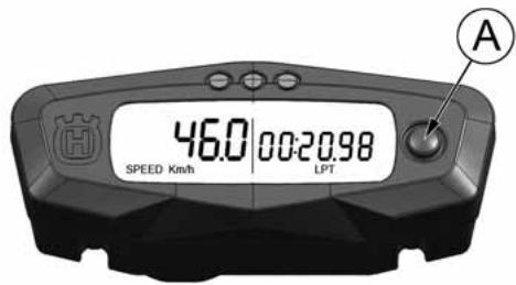
4- SPEED / CHRONO (STP) (figure 4)
- SPEED: motorcycle speedmaximum value: 299 Km/h o 299 mph;
- STP 1: miles/kilometers covered time;
- Reading from 0:00 to 99:59:59 (the data will be lost with voltage lower than 6V).
To activate the function STP 1, push the knob SCROLL (A) for more than 3 seconds. - 1st step: function ON;
- 2nd step: stop to the counters;
- 3rd step: STP 1 zero-setting; TRIP 1 and AVS 1 data zero-setting;
- 4th step: function ON;
- 5th step: stop to the counters;
and so following
THROTTLE CONTROL
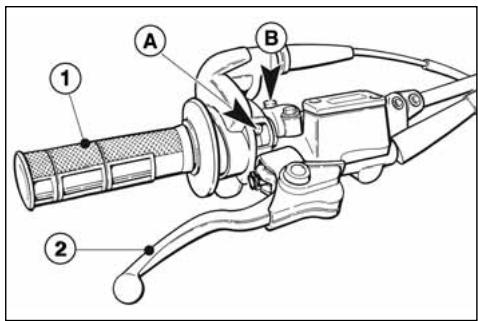
The throttle knob (1), is located on the right hand side of the handlebar. The position of the throttle control can be adjusted by loosening the two fastenig screws.
CAUTION
Do not forget to tighten the screws (A) after the adjustment.
FRONT BRAKE CONTROL
The brake control lever (2) is located on the right hand side of the handlebar. The position of the throttle control can be adjusted by loosening the two fastenig screws.
CAUTION
Do not forget to tighten the screws (B) after the adjustment.
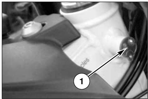
STEERING LOCK (WR)
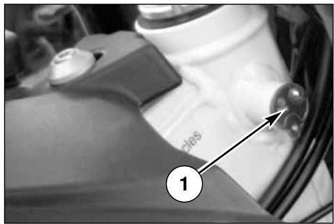
The motorcycle is equipped with a steering lock (1) on the R.H. side of the steering head tube.
To lock it, proceed as follows: turn the handlebar leftwards, place the key in lock and turn counterclockwise. Push the key inwards (if necessary, turn to and from). Turn the key clockwise and remove it from the lock.
To unlock the steering lock, reverse the above procedure.
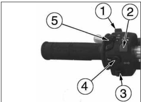
HANDLEBAR COMMUTATOR (WR)
The left commutator has the following controls:
1) Engine stop button (✗)
2) HI = ( D) Selection control High beam
LO = ( ≡D ) Selection control of Low beam
3) TURN
← = Activation of left turn indicators (self cancelling) → = Activation of right turn indicators (self cancelling)
To deactivate the indicator, press the control lever after its returning to center.
4) HORN = ( ) Warning horn
5) LIGHTS
☀️ = Lighting control of lowbeams and high beam.
≥ 0.0 ≤ = Lighting control of position lights.
● = 0ff
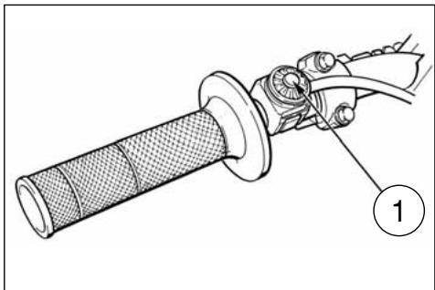
ENGINE STOP BUTTON (CR, WR USA-CDN)
On the left side of the handlebar, near the clutch control, is located the engine stop button (1).
CLUTCH CONTROL
The clutch lever is located on the left-hand side of the handlebar and is protected against dirt filtering in. The lever support is provided with adjusting screw (1) to regulate clutch wire free play (see on page 22). The clutch lever can be adjusted to suit your driving position.
natural_image
Technical line drawing of a mechanical component with labeled part (1), no readable text or symbols present.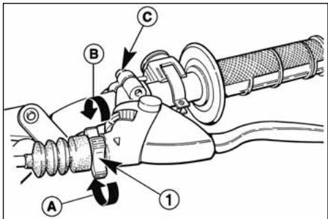
CAUTION
Do not forget to tighten the screws (C) after the adjustment.
A: To decrease clearance
B: To increase clearance
REAR BRAKE CONTROL
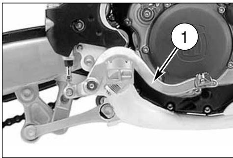
The rear brake control (1) is placed on the right-hand side of the motorcycle. On models WR a stop switch, during the braking action, causes the rear light to come on.
natural_image
Mechanical assembly diagram showing a motor and linkage mechanism (no text or symbols visible)GEAR SHIFT CONTROL
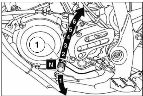
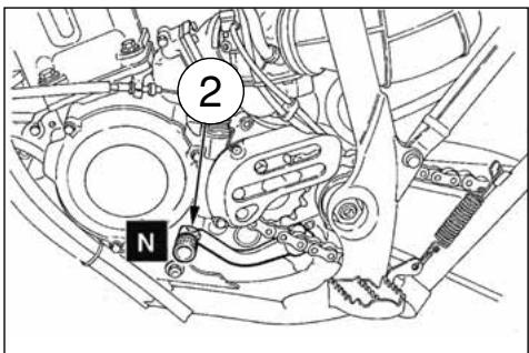
The lever (1) is placed on the left-hand side of the engine. The operator must release the lever after each gear change to allow it to return to its central position before another gear change can be made.
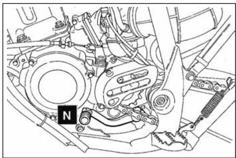
Neutral position (N) is between first (low) and second gears. First gear is engaged by pushing the lever downwards; all the other gears are engaged, by pushing the lever upwards.
The position of the gear shift lever on the shaft can be varied by: loosening screw; pulling lever out; placing lever in new position on the shaft when the operation is over tighten the screw and then tightening the screw.
CAUTION*: Do not shift gears without disengaging the clutch and closing the throttle. The engine could be damaged by "overspeed" and shock.
WARNING*: Do not downshift when traveling at a speed that would force the engine to overrev in the next lower gear, or cause the rear wheel to lose traction.
KICKSTART PEDAL
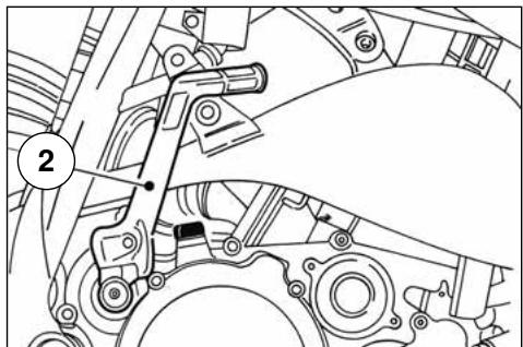
The kickstart pedal (2) is situated on the right-hand side of the motorcycle.
N: Neutral
natural_image
Mechanical assembly diagram showing gear and components without any text or symbolsRIDING
Before each ride, to prevent accidents or failures during ride, make sure to go through following list.
1. Check all fluids
A. Transmission oil level
B. fuel level
C. coolant level
Make sure all caps are properly adjusted.
WARNING\*: Don't remove radiator cap when hot!
2. Check all controls
A. Throttle handgrip
B. Clutch lever
Make sure cables are not damaged and turn smoothly.
3. Check brakes
Look for brake fluid leaks and worn hoses. Check for proper functioning.
4. Check suspensions
Compress fork and rear suspensions. Look for oil leaks and ensure proper functioning.
5. Check wheels
Check spokes and look for worn bearings.
Check rims and tyres.
Check tyre pressure.
6. Check chain rollers and sprockets
Check wear on chain rollers and sprockets Ensure chain is correctly adjusted and lubricated.
7. Check air filter and intake system
Check that air filter is clean Check all rubber connections and clamps.
8. Check exhaust system
Check hook up, look for cracks Check muffler.
9. Check torque
A. Spark plug (see page 23).
B. General check of torque
10. Check steering action
Check bearing play.
11. Check the electric system (WR).
Start the engine and check that the front and rear lamps, the stop light, the turn signals the cluster warning lights and the horn are working correctly.
WARNING\*: Failure to perform these checks every day before you ride may result in serous damage or a severe accident.
RUNNING IN
To obtain the best settling of the engine moving elements, for driving your motorcycle to the best of your capability, run in the engine for several hours, following these procedures:
-
FROM STOP POSITION. Start the engine and run at idle, but open the throttle periodically and briefly until the engine is thoroughly warmed up. Within 3-4 minutes the coolant temperature will have reached approximately 60^ / 140^ F. (Do not ride the motorcycle).
-
Stop the engine, and let it cool down naturally until its temperature is equal to the ambient air temperature. This will allow the piston to align itself to any imperfections which might exist at the cylinder wall.
-
Repeat steps 1 and 2. (Do not ride the motorcycle).
-
Bring the engine up to normal running temperature. Ride the motorcycle approximately 10 minutes at moderate speeds. Then repeat cool down procedure.AVOID HARD ACCELERATIONS.
-
Bring engine up to normal temperature. Ride motorcycle approximately 15 minutes at moderate to high speeds. Again avoid hard accelerations.
-
Repeat cool down procedure.
-
Full throttle operation must be avoided until the engine has reached operating temperature, even after the break in process is completed. When the above procedure is followed correctly, engine durability and performance will be greatly enhanced.
CHECKS WHILE RUNNING IN
When running in, the following should be checked out:
- WHEELS SPOKES TENSION (see page 50);
- TIGHTENING OF WHEELS
- FORK PIN TIGHTENING
- CHAIN ADJUSTMENT (see page 34);
- STEERING BEARING PLAY (see page 25);
- HANDLEBAR TIGHTENING
- ENGINE GRIP TO FRAME
- SUCTION FITTING GRIP
- HEAD AND CYLINDER NUTS GRIP
Note*: After break in, install a new spark plug and change the transmission oil.
ENGINE START
For the correct start of a cold engine proceed as follows:
- shift the transmission into neutral;
- set fuel valve (1) in ON position;
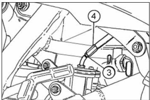
- lift the knob lever (3) on the carburetor.
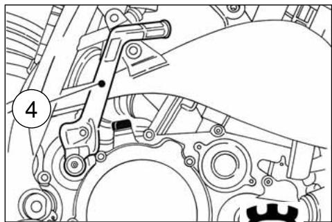
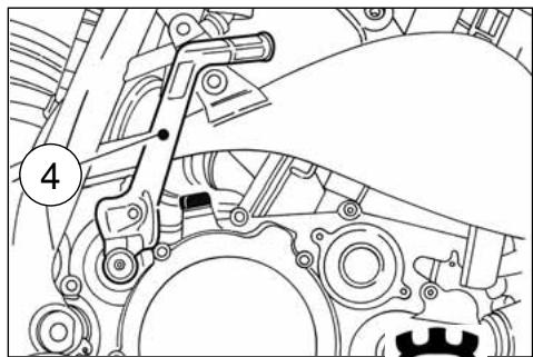
Leaving the throttle in closed position operate kick-start (4).
Take the knob lever in its initial position as soon as the engine is idling.
When starting with an already warmed up engine DO NOT USE the starter. You can start the engine with the gear inserted, after disconnecting of the clutch.
If the carburetor is flooded, shut off the fuel supply and the starter and operate the crank lever or the kick-start until the engine starts. If necessary, remove the spark plug and dry it.
IMPORTANT NOTE IN CASE OF COLD STARTS AT LOW TEMPERATURES
It is recommended to briefly warm-up the engine at idle until, after having disengaged the starter, there is a normal response from the engine when opening the throttle.
This will enable the lubricant to reach the correct working temperature thereby guaranteeing a correct functioning of all engine parts.
Avoid overheating the engine.
IMPORTANT
Never accelerate the engine after a cold start.
WARNING*: Exhaust contains poisonous carbon monoxide gas. Never run the engine in a closed garage or in a confined area.
WARNING*: This high performance motorcycle can some times «kick back» strongly when you are starting it.
Do not attempt to start this motorcycle unless you are wearing high top heavy sided riding boots. You could seriously hurt you leg if the kickstarter kicked back and your foot slipped.
natural_image
Technical line drawing of a mechanical assembly with no visible text or symbols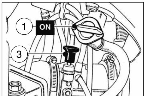
natural_image
Mechanical assembly diagram showing gear and shaft components (no text or labels)STOPPING THE MOTORCYCLE AND THE ENGINE
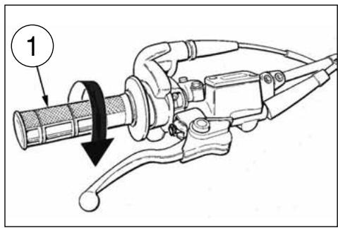
- Close the throttle (1) completely so that the engine will help slow down the motorcycle.
- For normal braking, gradually apply both front and rear brakes while down shifting (for maximum deceleration, apply the front and rear brakes firmly).
- When stopped, pull the clutch lever and shift gear lever (2) in neutral position.
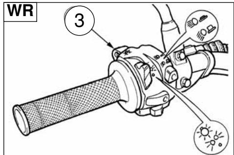
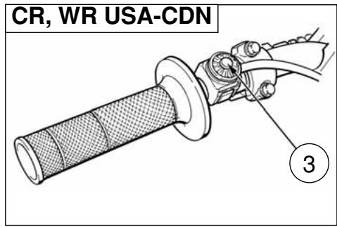
- Press the engine stop button (3).
- Close the fuel cock (4).
When the bike is off, place it on its side stand.
TRANSMISSION OIL LEVEL CHECKING
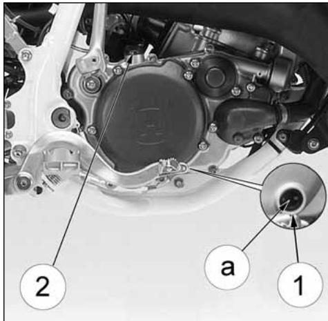
A. Transmission oil level
Keeping the motorbike level and in a vertical position, check the oil level through the inspection (1) window on the right crankcase. Check if level (a) is about midway of the inspection porthole.
Note*: Have this operation made with warmed-up engine.
WARNING*: Be careful not to touch hot engine oil
TRANSMISSION OIL CHANGE
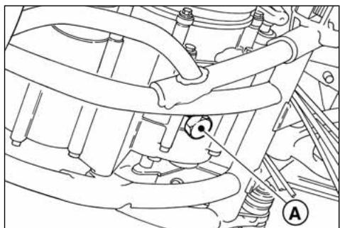
To completely replace the oil, unscrew the plug (A) under the oil sump and let oil come out, then screw the plug again with its gasket and pour fresh oil from the hole of the loading plug. Use only the prescribed quantity and type of oil (see on page 8)
Note:
Have this operation made with warmed-up engine.
A: Draining plug
COOLANT LEVEL CHECK
Check level (1) in right-hand radiator when engine is cold (place the motorcycle so that it is perpendicular to the ground). The coolant should be approximately 10 mm above cells.
The radiator cap is provided of two unlocking positions, the first being for the previous pressure discharge in the cooling system.
WARNING
Avoid removing radiator cap when engine is hot, as coolant may spout out and cause scalding.
NOTE
Difficulties may arise in eliminating coolant from varnished surfaces. If this occurs, wash off with water.
natural_image
Technical line drawing of a mechanical assembly with no visible text or symbols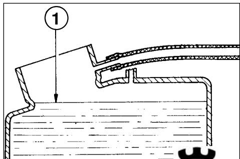
REPLACEMENT OF COOLING FLUID
The cooling liquid replacement must be performed with cold motor, as follows:
- remove the R.H. radiator plug;
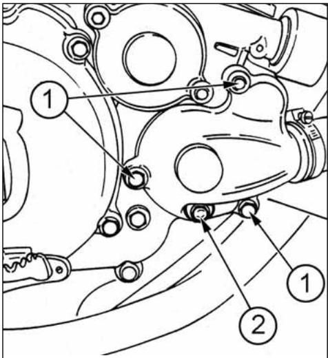
- remove the drain screw (2) on the pump cover or the pump cover by loosening the three screws (1);
- slope the motorbike on the right, to make the liquid come out easily;
- let the liquid drain completely;
- reassemble the drain screw or the pump cover;
- pour the necessary quantity of liquid in the radiator (page 8);
- warm up the motor in order to eliminate any possible air bubble;
- fit the motor in vertical position and check that the liquid in the radiators must be 10 mm/0.4 in. over the radiant mas (if not, top it up);
- screw the R.H. radiator plug.
WARNING\*: Coolant on tires will make them slippery and can cause an accident or injury.
Periodically check the connecting hoses (see "Periodical maintenance card"): this will avoid coolant leakages and consequent engine seizure: If hoses show cracks, swelling or hardenings due to sheats desiccation, their
replacement shall be advisable. Check the correct tightening of the clamps.
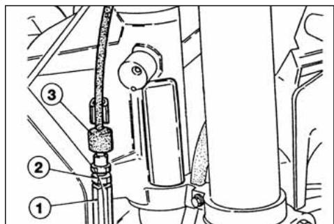
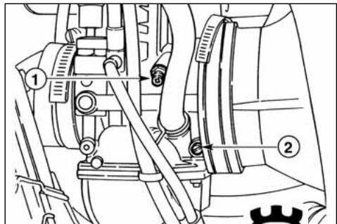
THROTTLE CABLE ADJUSTMENT
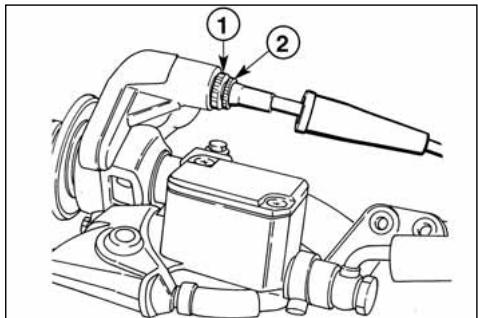
The throttle cable can be adjusted using the screw set on the throttle, or using the adjusting screw set on the
carburettor cover. To check for proper adjustment of throttle cable, proceed as follows:
- remove rubber cap;
- move transmission sheath to and fro to ensure a play of approx. 1 mm;
- should play be greater than 1 mm, loosen lock nut (1) and register (2); should play less than 1 mm, then tighten lock nut and register;
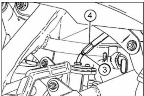
- if register (2) should not provide sufficient movement to allow for correct adjustment, then adjust register placed on carburetor.
There should be approx. 1 mm play on latter register; should this not be the case, then loosen lock nut (3), and loosen or tighten screw (4), to respectively increase or decrease the play.
WARNING*: Operation with damaged throttle cable could result in an unsafe riding condition.
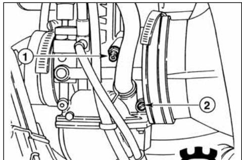
IDLING ADJUSTMENT
Idling should be adjusted only when the engine is hot and throttle is closed, as follows:
- turn idle adjusting screw (1) so as to increase rpm (turn clockwise to increase rpms, counterclockwise to decrease rpm);
- turn fuel mixture adjusting screw (2) clockwise or anticlockwise until engine runs smoothly;
- gradually loosen screw (1) to ensure that engine runs properly.
WARNING*: Exhaust gas contains poisonous carbon monoxide gas. Never run the engine in a closed area or in a confined area.
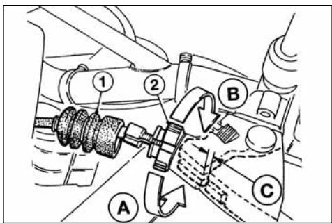
CLUTCH ADJUSTMENT
The clutch is adjusted by stretching the cable using the adjusting unit positioned on the handlebar.
As a rule it is sufficient to operate on the handlebar register to restore the clearance due to the flexible transmission stretch. The control lever must always have an empty stroke (C) (3 mm) before starting clutch disengagement. To adjust this clearance, act on register (2) after taking out rubber cap (1); turn the register in the direction indicated by arrow A to reduce the clearance (C); turn it in the direction indicated by arrow B to increase the clearance.
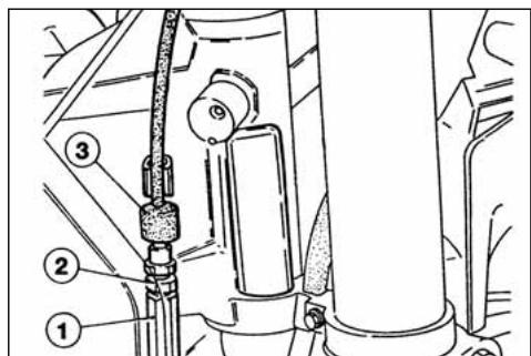
The adjustment can be also effected with tightener (1) set on the right of the frame. Take care to tighten properly the lock nut. If the clutch slips under load or drags in disengaged position after play has been adjusted, it must be taken apart for inspection. For this operation apply to a Dealer.
- Rubber cap
-
Adjusting screw
-
Adjusting screw
- Locknut
- Rubber cap
CONTROLLO CANDELA
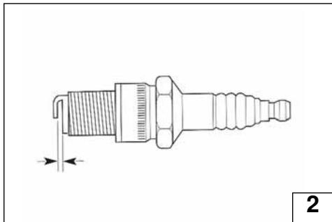
Use NGK BR9EG or CHAMPION QN84; spark plug (2); the gap is 0,6÷0,7 in.
A wider gap may cause difficulties in starting engine and in overloading coil.
A gap that is too narrow may cause difficulties when accelerating, when idling the engine or when performing at low speeds.
Clean the dirt away from the base of the spark plug before removing it from the cylinder after removing the cap (1).
It is very useful to examine the state of the spark plug just after it has been removed from the engine since the deposits on the plug and the colour of the insulator provide useful indications.
Correct heat rating:
The tip of the insulator should be dry and the colour should be light brown or grey.
High heat rating:
In this case, the insulator tip is dry and covered with dark deposits. Low heat rating:
In this case, the spark plug is overheated and insulator tip is vitreous, white or grey in colour.
CAUTION*: Select a spark plug with a colder or hotter heat range carefully and cautiously. A spark plug with too hot a heat range may lead to preignition and possible engine damage. A spark plug with too cold a heat range may foul as the result of too much carbon buildup.
Before refitting the plug, thoroughly clean the electrodes and the insulator using a brass-metal brush.
Apply a little graphite grease to the spark plug thread; fit and screw the spark plug by hand then tighten to the torque of 23,5÷25,5 Nm-17,3÷18,8 ft/lb.
Spark plugs which have cracked insulators or corroded electrodes should be replaced.
VOLTAGE REGULATOR (WR)
The voltage regulator (1) is located on the frame, under the fuel tank.
natural_image
Technical line drawing of a spark plug with threaded end and shaft (no text or symbols)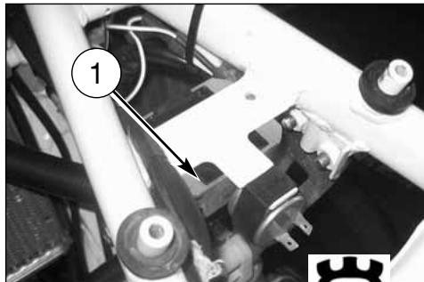
natural_image
Close-up of mechanical components with numbered annotation (1) and a gear icon, no readable text or symbols present.AIR FILTER CHECK
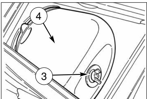
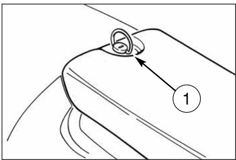
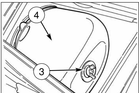
Turn rear pin (1) counterclockwise, remove the saddle from the front afstening screw.
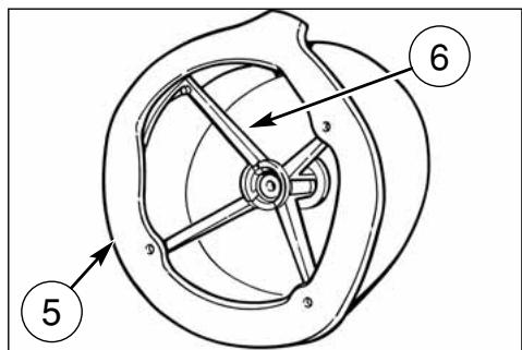
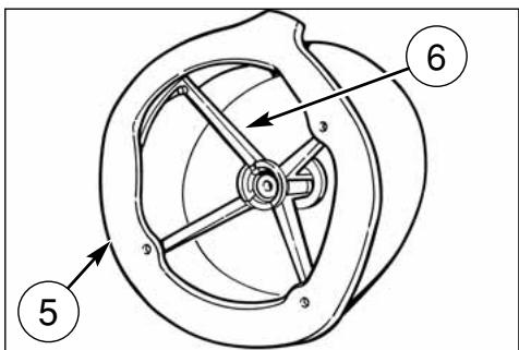
Remove screw (3) and the filter (4). Separate filter (5) from frame (6).
AIR FILTER AND CLEANING
Wash the filter with a specific detergent (CASTROL FOAM AIR FILTER CLEANER or similar) then dry it fully (wash filter with gasoline only in case of necessity).
Plunge the filter in special oil for filters (CASTROL FOAM AIR FILTER OIL or similar) then wring it to drain superfluous oil.
CAUTION*: Do not use gasoline or a low flash-point solvent to clean the element. A fire or explosion could result.
CAUTION*: Clean the element in a well ventilated area, and do not allow sparks or flames anywhere near the working area.
ASSEMBLY
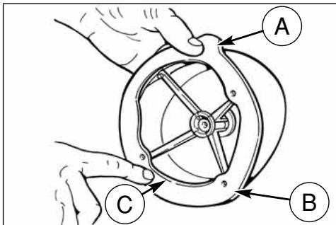
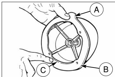
To ensure tight fit, slightly (C) grease filter edge on side facing filter housing.
While re-inserting the filter into its housing, make surs that piece (A) is turned upwards and edge (B) is on the left lower side of the filter case. Reassemble the parts previously removed (battery: connect the positive cable first).
CAUTION*: If the element assembly is not installed correctly, dirt and dust may enter and the engine resulting in rapid wear of the piston rings and cylinder.
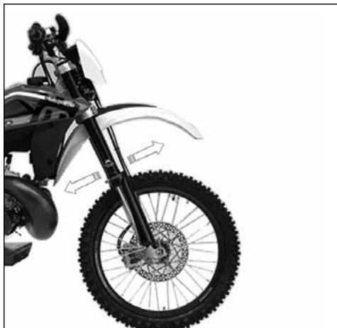
STEERING WHEEL BALL PLAY ADJUSTMENT
To ensure maximum safety, the steering wheel should always be regulated so that the handlebars steering the motorcycle rotate freely without play. To check steering wheel adjustment, place kick stand or other support under the engine so that the front wheel is raised from ground.
Place slight pressure on the tips of the handlebars to rotate steering wheel; the handlebars should also rotate without effort.
- loosen steering sleeve nut (1).
- Loosen four screws that fix steering head to fork rods (3). Turn the steering ring nut (2) clockwise of the steering sleeve proper tool, to adjust play properly.
- Tighten steering sleeve nut (1) to a torque setting of 57,9÷65,1 Lb/ft; (78,4÷88,3 Nm).
- Tighten four screws on the steering head (3) to a torque of 22,5÷26,5 Nm (16.6÷19.5 Lb/ft).
CAUTION*: Do not ride a motorcycle with damaged steering stem bearings. An unsafe handling condition can result.
natural_image
Side view of a black-and-white photo of a motorcycle's front wheel and side gear (no text or symbols visible)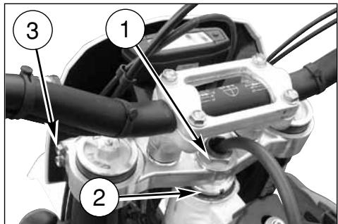
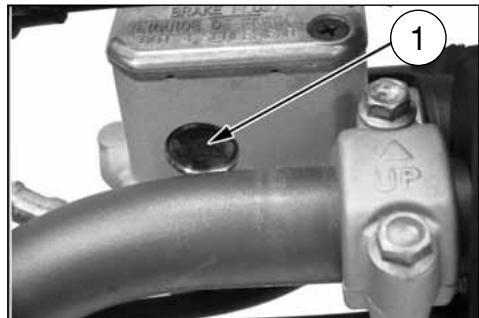
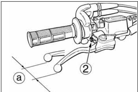
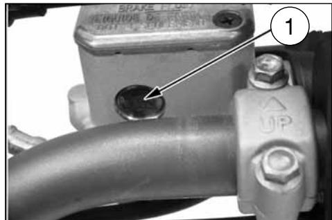
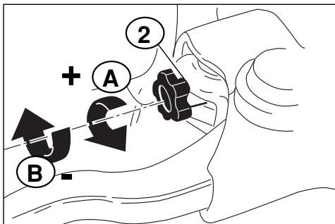
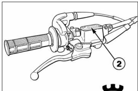
The adjuster (2), located on the control lever, allows adjusting of the free play (a).
Free play (a) must be at least 3 mm (0.1 in.).
The level of the fluid in pump reservoir must never be below the minimum value (1), which can be checked from the window on the rear side of the pump body.
A decrease of the fuel level will let air into the system, hence an extension of the level stroke.
WARNING*: If the brake lever feels mushy when it is applied, there may be air in the brake lines or the brake may be defective. Since it is dangerous to operate the motorcycle under such conditions, have the brake checked immediately by an authorized HUSQVARNA dealer.
CAUTION*: Do not spill brake fluid on to any painted surface or lenses.
CAUTION*: Do not mix two brands of fluid. Change the brake fluid in the brake line if you wish to switch to another fluid brand.
CAUTION*: Brake fluid may cause irritation. Avoid contact with skin or eyes. In case of contact, flush thoroughly with water and call a doctor if your eyes were exposed.
A: to encrease clearance
B: to decrease clearance
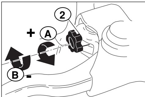
REAR BRAKE PEDAL POSITION ADJUSTMENT
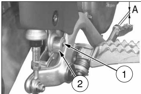
The position of the rear foot brake pedal as to the footrest may be adjusted according to the individual needs. For the adjusting proceed as follows:
- loosen the screw (1);
- turn the cam (2) in order to adjust the brake pedal idle stroke (A);
- the operation done, tighten the screw (1).
The adjusting operation carried out, adjust the idle stroke of the pedal as follows..
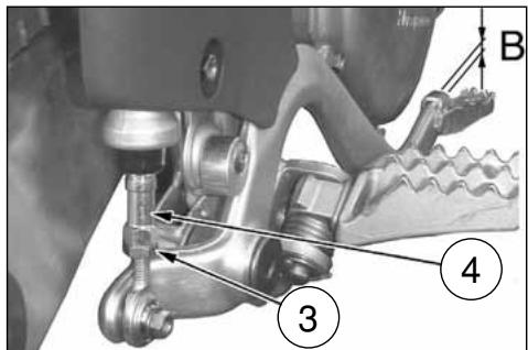
REAR BRAKE IDLE STROKE ADJUSTMENT
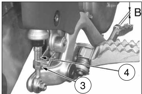
The rear brake foot pedal should have a (B) 5 mm (0.2 in.) idle stroke before starting the true braking action.
Should this not happen, operate as follows:
- loosen nut (3);
- operate the pump rod (4) to increase or decrease the idle stroke;
- tighten nut (3) at the end of the operation.
WARNING
When the idle stroke figures are not met, the brake pads will be subjected to a fast wear that may bring to the TOTAL BRAKE IN-EFFECTIVENESS.
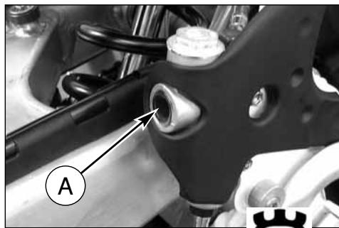
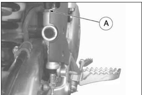
CHECKING THE FLUID LEVEL
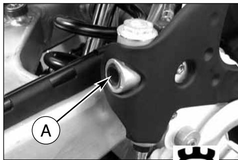
The level (A) must be set between the pump tank notches.
natural_image
Mechanical assembly diagram showing a bracket with labeled component A (no text or symbols beyond label)ADJUSTING THE SUSPENSIONS ACCORDING TO PARTICULAR TRACK CONDITIONS
The following information is a useful guide for setting up the suspensions according to the road conditions.
Always start from the standard calibration before making any change on the suspensions. Afterwards, increase or decrease the adjusting clicks one at a time.
HARD GROUND
Fork: softer compression adjustment.
Shock absorber: softer compression adjustment.
The softer adjustment for the two suspensions is also used both in compression and in extension when driving at top speed, in order to have better grip of the tires.
SANDY GROUND
Fork: have a harder compression adjustment, or replace the standard spring with a harder one, and make a softer compression adjustment and a harder extension adjustment at the same time.
Shock absorber: have a harder compression, and especially a harder extension adjustment. Work on the spring preload to lower the motorcycle rear side.
MUDDY GROUND
Fork: have a harder compression adjustment, or replace the standard spring with a harder one.
Shock absorber: have a harder compression and extension adjustments, or replace the standard spring with a harder one. Work on the spring preload to lift the motorcycle rear side.
We advise replacing the springs of both suspensions to compensate the weight increase due to the piling of the mud.
NOTE:
When the fork results as either too soft or too hard for any adjustment conditions, check the oil level inside the forkrod.
The level can either be too low or too high. Remember that too much oil inside the fork will involve a more frequent air drainage. When the suspensions do not react to the changes of calibration, check that the adjusting units are not blocked.
natural_image
Black-and-white photo of a motorcyclist riding a dirt bike across a dusty terrain under cloudy skies (no text or symbols visible)
natural_image
Black-and-white photo of a dirter in action on a dirt track, wearing helmet and racing gear, with 'ROTOM' banners visible in background (no readable text on rider or equipment)The standard calibrations and the adjustment procedures are shown below.
ADJUSTING THE COMPRESSION FORK
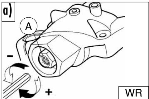
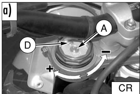
a) COMPRESSION (CR: UPPER REGISTER; WR: LOWER REGISTER) Standard calibration: -9 clicks (CR) Standard calibration: -10 clicks (WR)
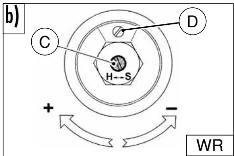
Remove plug (B) and turn register (A) clockwise until the position of fully closed is reached then, turn back by the mentioned clicks. To obtain a smoother braking action, turn the register anticlockwise. Reverse the operation in order to obtain a harder action.
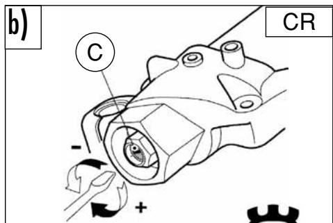
b) EXTENSION (CR: LOWER REGISTER; WR: UPPER REGISTER) Standard calibration: -13 clicks (CR) Standard calibration: -10 clicks (WR)
To reset standard calibration turn register (C) clockwise to reach the position of fully closed; then, turn back by the mentioned clicks. To obtain a smoother braking action, turn the register anticlockwise. Reverse the operation in order to obtain a harder action.
c) AIR VENT (to carry out after each competition, or monthly). Set the motorcycle on a central stand and release the fork fully and loosen the air vent valve (D). Once this operation is over, tighten the valve.
WARNING: Never force the adjusting screws beyond the maximum opening and closure positions.
OIL FORK LEVEL
For the regular fork operation, both legs must be provided with the necessary oil quantity.
WR: Remove the forkrods form the fork to check the oil level inside the forkrods. Work as follows:
- remove the power rod caps;
- remove springs from the stems letting the oil drop into the latter;
- bring forks to stroke end;
- check that the level is at distance "A" below the upper limit of rods.
OIL QUANTITY IN EACH FORK LEG
-CR: 352 cm ^4
-WR: 643 cm ^3
NOTE
Flexibility index for the serial springs:
K=8,8 N/mm (CR)
K=8,4 N/mm (WR)
NOTE
Always replace both the spring and the spacers to keep the preload value unchanged.
HANDLEBAR POSITION AND HEIGHT CHANGE
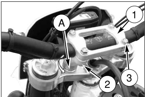
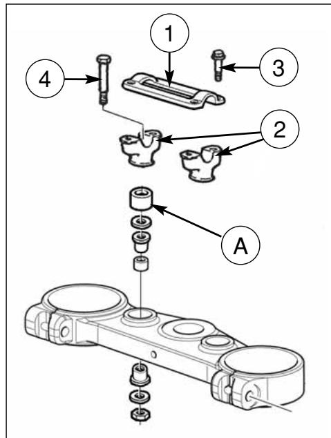
The handlebar position (a) and height (b) can be changed for better suiting Your driving requirements. To effect these operations, remove the upper clamp (1) and the lower one (2), after removing the fixing screws (3) and (4).
a) Handlebar position change
Turn the lower clamp (2) 180° to move forward or backward (10mm- 0.04in.) the handlebar position with respect to the original setup.
b) Handlebar height change
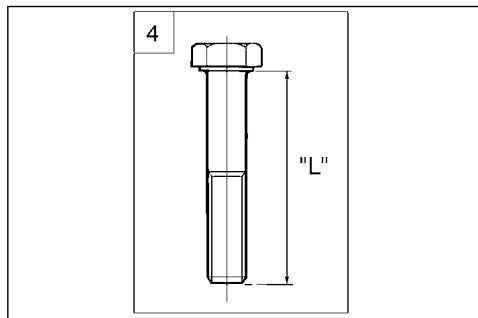
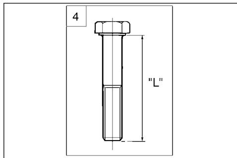
Remove the lower spacer (A) then replace the screw (4) with a new one of L=65 mm (2.56 in.) height.
Once these operations are completed, tighten the screws (3) to 2,75-3,05 kgm (27-30 Nm; 19.9-22 Lb/fts) and the screws (4) to 2,0-2,2 kgm (19,6-21,6 Nm; 14.5-15.9 Lb/fts
The rear shock absorber must be adjusted according to the rider weight and track conditions.
Proceed as follows:
- With motorcycle on the stand, measure distance (A).
- Take the normal riding position on the motorcycle with all your riding apparel.
- With somebody's help, take the new distance (A).
B: axis of the panel screw
C: axis of rear wheel pin
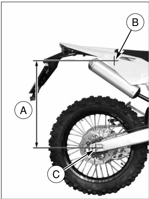
- The difference between these two measurements constitutes the "SAG" of the motorcycle's rear end.
Suggested SAG: 4 in. with cold shock absorber. 3.7 in. with warmed up shock absorber. - To get the right SAG according to your weight, adjust the shock absorber spring preload as described at side.
WARNING*: Never disassemble shock absorber, which contains highly compressed nitrogen. Contact your Dealer for such major service. Do not incinerate.
natural_image
Diagram of a mechanical component with a circular part labeled '1' and curved lines, no readable text or symbols present.ADJUSTING THE SHOCK ABSORBER SPRING PRELOAD
Proceed as follows:
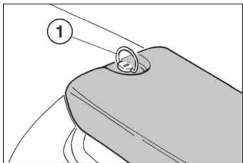
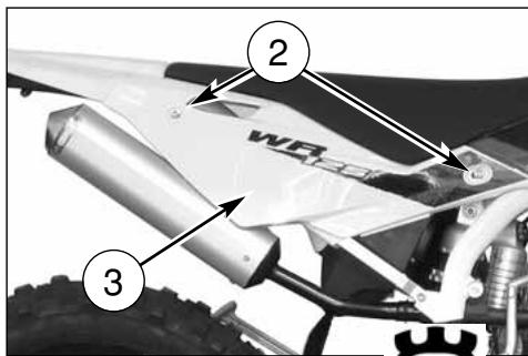
- First turn counterclockwise fastening rear pin (1) then remove saddle, screws (2) and R.H. side panel (3).
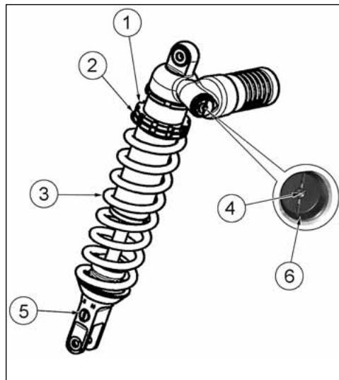
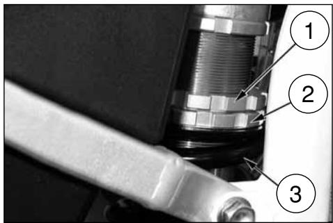
- Clean ringnut (1) and adjusting nut (2) of the spring (3).
- Either with a hook wrench or an aluminium punch, loosen the ringnut.
- Turn the adjusting nut as required.
- When the adjusting operation is over (according to your weight and riding style), tighten the ringnut. (Torque for both ringnuts: 5 Kgm; 49 Nm; 36.2 ft/lb).
- Reassemble R.H. side panel and saddle.
WARNING*:Be careful not to touch hot exhaust pipe while adjusting the shock absorber.
SHOCK ABSORBER DAMPING ADJUSTMENT
Adjustment of the compression stroke is independent from the rebound stroke.
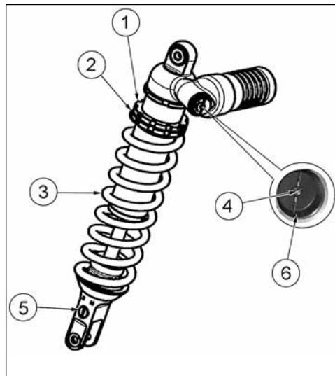
A) COMPRESSION - Standard calibration:
1) Low damping speed:
- 15 clicks (± 2 clicks)
(register 4)
2) High damping speed:
- 15 clicks (± 2 clicks)
(register 6)
To reset the standard calibration, turn upper registers (4) and (6) clockwise until reaching fully closed position.
Return then back for the mentioned clicks. In order to obtain a smooth braking action, turn the registers anticlockwise. Reverse the operation in order to obtain a harder braking action.
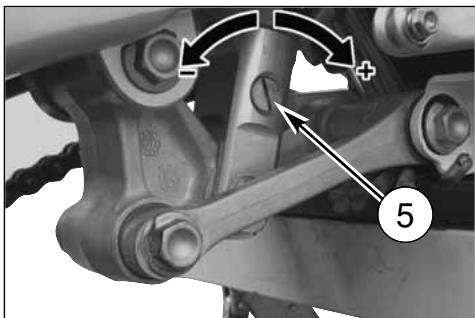
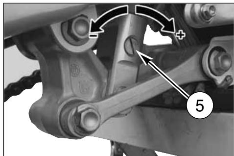
B) EXTENSION - Standard calibration:
- 18 clicks (± 2 clicks)
To reset the standard calibration, turn lower register (5) clockwise until reaching fully closed position. Return then back for the mentioned clicks. In order to obtain a smooth braking action, turn the register anticlockwise. Reverse the operation in order to obtain a harder braking action
natural_image
Mechanical assembly diagram showing linkage components with arrows indicating motion direction (no text or symbols)CHAIN ADJUSTMENT (Fig. A)
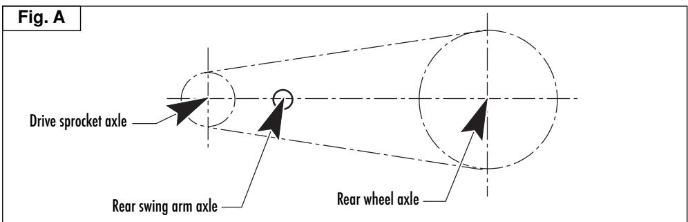
Chain should be checked, adjusted and lubricated as per the Maintenance Chart to ensure security and prevent excessive wear. If the chains becomes badly worn or is poorly adjusted (i.e., if it is too loose or too taught), it could escape from sprocket or break.
To adjust the rear chain it is necessary to lower the rear part of motorcycle so to line up the drive sprocket axle, the rear swing arm axle and the rear wheel axle as shown on drawing. Than let turn three times the rear wheel. Now the chain should not be tight.
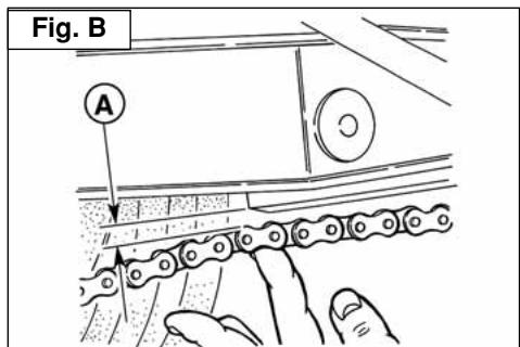
Fast adjustment (Fig. B.)
Push the chain towards the final part of runner and check that between the two elements a distance "A" from 0 to 2 mm is present. If this is not the case, go on as follows:
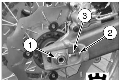
- Unloose the fastening nut of the wheel pin (1) on the right side;
- Unloose the lock nuts (2) on both chain adjusters and turn the screws (3) to obtain the correct tension value;
- Tighten the lock nuts.
After adjustment check that the wheel is lined up and tighten its axle.
CHECKING THE WEAR OF CHAIN, PINION AND SPROCKET
Proceed as follows:
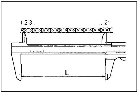
- fully stretch the chain with the adjusting screws.
- mark 20 chain links.
- measure the distance "A" between 1st pin center and 21 st pin center.
| STANDARD | WEAR LIMIT |
| 317,5 mm(12,5 in) | 323 mm(12,72 in) |
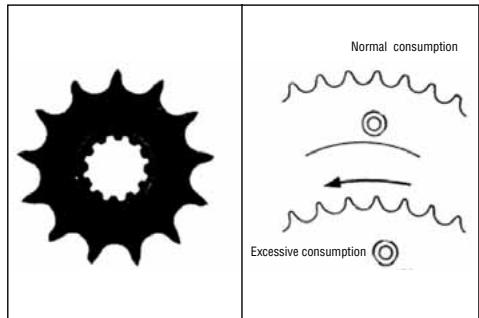
Check the pinion damages or wear and replace it should the wear degree be as the one shown in figure.
Remove the wheel and check the wear of the rear sproket teeth. The below figure shows the outline of teeth in normal and excessive wear. Should the sprocket be badly worn out, replace it by loosening the six fastening screws to the hub.
WARNING*: Misalignment of the wheel will result in abnormal wear and may result in an unsafe riding condition.
Note*: In muddy and wet conditions, mud sticks to the chain and sprockets resulting in an overtight chain. The pinion, the chain, and the rear sprocket wheel wear increases when running on muddy ground.
LUBRICATING THE CHAIN
Lubricate the chain following these instructions.
WARNING * : Never use grease to lubricate the chain. Grease helps to accumulate dust and mud, which act as abrasive and hepl to rapidly wear out the chain, the sprocket, and the crown.
Disassembling and cleaning
When particularly dirty, remove and clean the chain before lubrication.
Work as follows:
1 - Set a stand or a block under the engine and see that the rear wheel is lifted from the ground.
Remove: screws (1), transmission sprocket guard (2), clip (3), master link (4) and transmission chain (5);
To reassemble, reverse the above procedure.
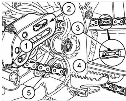
2 - Check that the chain is neither worn out nor damaged. If the rollers or the links are damaged, replace the chain by following the instructions given in the Periodical Maintenance Table.
3 - Check that neither the sprocket nor the crown are damaged.
4 - Wash and clean the chain as described hereunder.
Washing the chain without OR (\*)
Wash using either oil or diesel oil. When using gasoline or tricloroetilene, clean and lubricate the chain to prevent oxidation.
Washing the chain with OR ( · )
Wash using oil, diesel oil, or paraffin oil. Never use gasoline, tricloroetilene, or solvents, as the OR may suffer damages. Use instead special sprays for chains with OR.
Lubricating the chain without OR (\*)
First dry, then plunge the chain in a bisulphide molybdenum lubricant, or in high viscosity engine oil. Warm up the oil before use.
(*): CR (•): WR
Lubricating the chain with OR ( · )
Lubricate all metallic and rubber (OR) elements using a brush, and use engine oil with SAE 80-90 viscosity for the internal and external parts.
5 - If the chain has been cut, reassemble using a joint.
6 - Assemble the joint spring (a) by turning the closed side to the chain direction of rotation as shown in figure below.
NOTE*: Even if all the joints are reusable when in good conditions, for safety purposes we advise using new joints when reassembling the chain.
7 - Accurately adjust the chain as described on page 33.
WARNING: The chain oil has NEVER to get in contact with the tires or the rear brake disk.
Chain tension rollers, chain driving roller, chain guide, chain runner
Check the wear of the above mentioned elements and replace them when necessary.
WARNING*: Check the chain guide alignment, and remember that a bent element can cause a rapid wear of the chain. In this case, a chain fleeting from the sprocket may ensue.
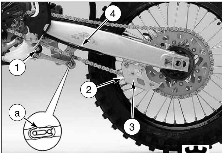
1- Chain tension roller
2- Chain driving roller
3- Chain guide
4- Chain slider
α- Joint spring
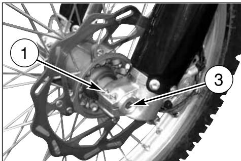
REMOVING THE FRONT WHEEL
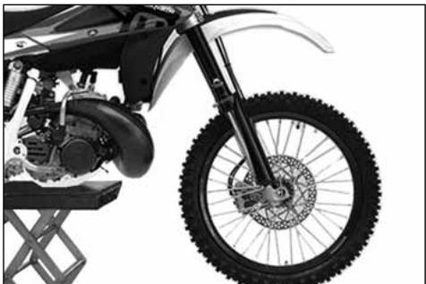
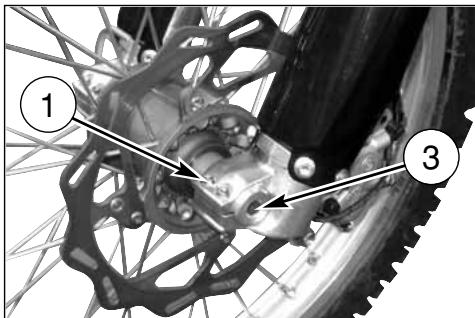
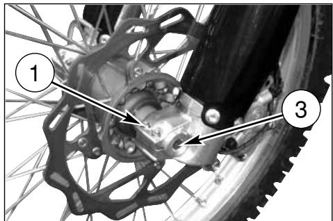
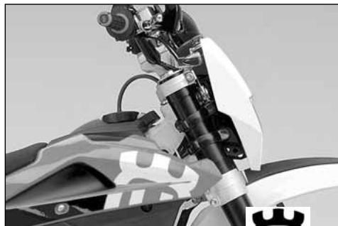
Set a stand or a block under the engine and see that the front wheel is lifted from the ground. Loosen the bolts (1) holding the wheel axle (2) to the front fork stanchions.
Hold the head of the wheel axle (2) in place, unscrew the bolt (3) on the opposite side; draw the wheel axle out.
NOTES
Do not operate the front brake lever when the wheel has been removed; this causes the caliper piston to move outwards. After removal, lay down the wheel with brake disc on top.
natural_image
Close-up of a black-and-white photo of a motor with visible wheels and engine components (no text or symbols)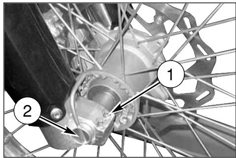
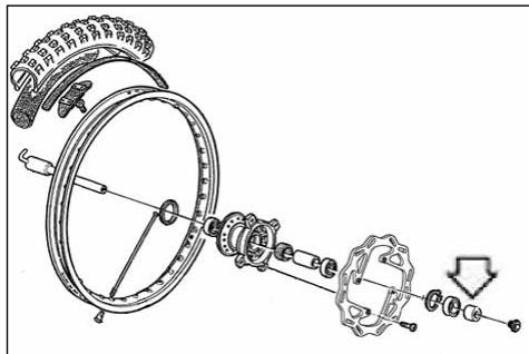
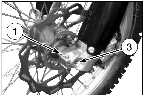
REASSEMBLING THE FRONT WHEEL
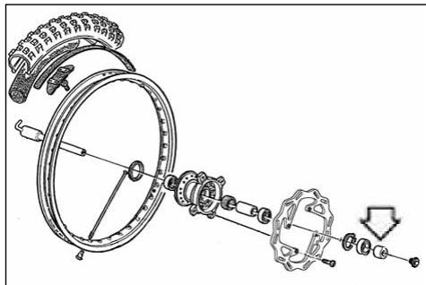
Fit the L.H. spacer on the wheel hub.
Fit the wheel between the front fork legs so that the brake disc is fitted into the caliper.
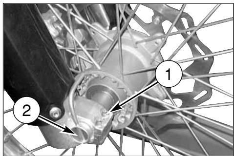
Fit the wheel axle (2) from the R.H. side, after greasing it and push it to the stop on the L.H. leg; during this operation, the wheel should be turned. Tighten the screw (3) on the fork L.H. side but DO NOT lock it. Now, pump for a while, pushing the handlebar downwards until you are sure that the fork legs are perfectly aligned.
Lock: the screws (1) on the R.H. leg (10,4 Nm/ 1,05 Kgm/ 7.7 ft-lb), the screw (3) on the L.H. side (51,45 Nm/ 5,25 Kgm/ 38 ft-lb), the screws (1) on the L.H. leg (10,4 Nm/ 1,05 Kgm/ 7.7 ft-lb).
Check that the brake disc slides between the caliper pads without any friction.
NOTE
After reassembly, pump the brake control lever until the pads are against the brake disc.
natural_image
Close-up of a motorcycle's front wheel and suspension system (no visible text or symbols)REMOVING THE REAR WHEEL
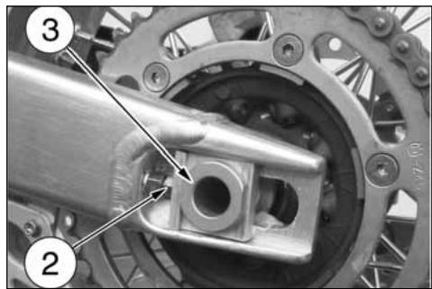
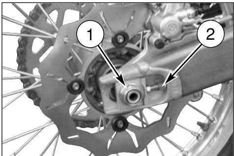
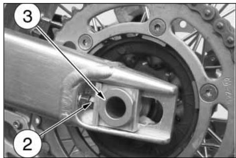
Unscrew the nut (1) of the wheel pin (3) and extract it. It is not necessary to unloose the chain adjusters (2); in this way, the chain tension will remain unchanged after the reassembly. Extract the complete rear wheel, by taking care of the spacers located at the hub sides.
To reassemble, reverse the above procedure remembering to insert the disc into the caliper.
NOTES
Do not operate the rear brake pedal when the wheel has been removed; this causes the caliper piston to move outwards. After removal, lay down the wheel with brake disc on top. After reassembly, pump the brake control pedal until the pads are against the brake disc.
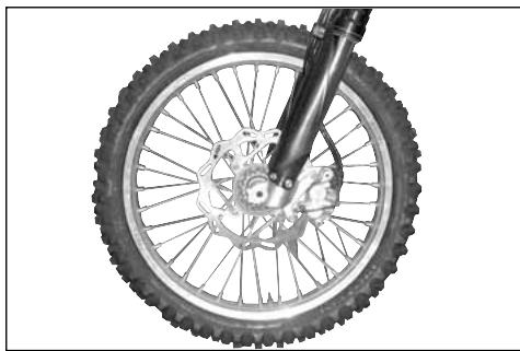
TIRES
Care should be taken to keep the tires properly inflated. See tire data for correct tire inflation pressure (page 8). Replace the tire if its wear exceeds what is shown on the table below.
MINIMUM HEIGHT OF THE TREAD
| FRONT | 3 mm (0.12 in) |
| REAR | 3 mm (0.12 in) |
natural_image
Top-down view of a bicycle wheel with visible tire, disc, and hub (no text or symbols)BRAKES
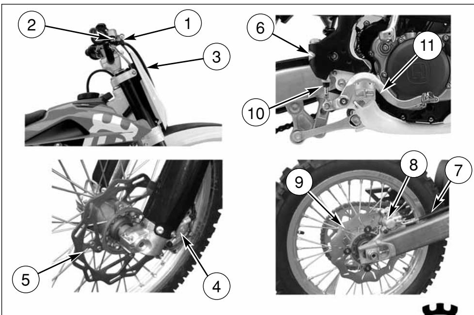
The mayor components are brake master cylinder with its lever (front) or pedal (rear), brakeline, caliper assembly and disc.
LEGEND
- Front brake control lever
- Front brake pump with oil reservoir
- Front brake hose
- Front brake caliper
-
Front brake disc
-
Rear brake oil tank
- Rear brake hose
- Rear brake caliper
- Rear brake disc
- Rear brake pump
- Rear brake control pedal
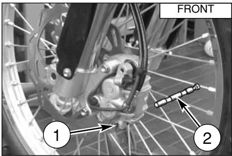
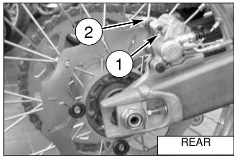
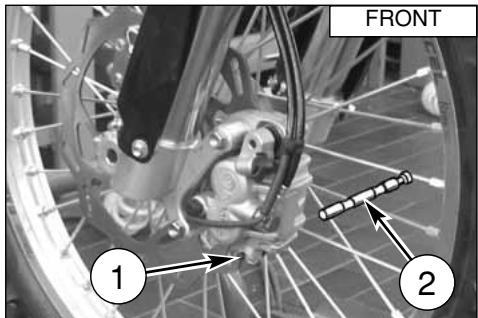
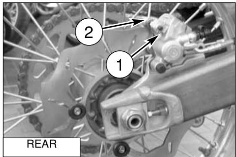
BRAKE PADS REMOVAL
- Remove springs (1).
- Remove pins (2).
- Remove pads.
CAUTION!
Don't operate the brake lever or pedal while removing the pads.
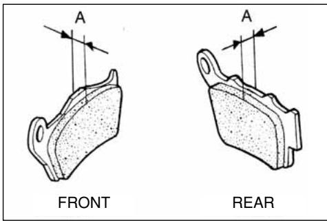
PADS WEAR
Inspect pads for wear.
Service limit "A" is: 3,8 mm (0.15 in.).
If service limit is exceeded, always replace the pads in pairs.
PADS CLEANING
Be careful that no disc brake fluid or any oil gets on brake pads or discs. Clean off any fluid or oil that inadvertently gets on the pads or disc with alcohol.
Replace the pads with new ones if they cannot be cleaned satisfactorily.
PADS INSTALLATION
- Install new brake pads.
- Reassemble the two pins (2) and the springs (1).
WARNING!
Do not attempt to ride the motorcycle until the brake lever or pedal are fully effective. Pump the brake lever or pedal until the pads are against the discs. The brake will not function on the first application of the lever or pedal.
BRAKE DISC WEAR
Measure the thickness of each disc at the point where it has worn the most. Replace the disc if it has worn past the service limit.
Disc Thickness
| DISC | STANDARD | SERVICE LIMIT |
| Front | 3 mm(0.12 in) | 2,5 mm(0.10 in) |
| Rear | 4 mm(0.16 in) | 3,5 mm(0.14 in) |
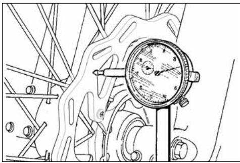
DISC WARPAGE
Measure disc warpage. Service limit for both discs is 0,15 mm (0.006 in.)
Replace the disc if warpage is more than service limit.
natural_image
Technical line drawing of a mechanical pressure gauge mounted on a stand, surrounded by scaffolding (no text or symbols)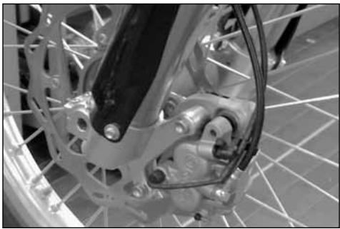
natural_image
Close-up of a bicycle wheel assembly with visible mechanical components and mounting brackets (no text or symbols)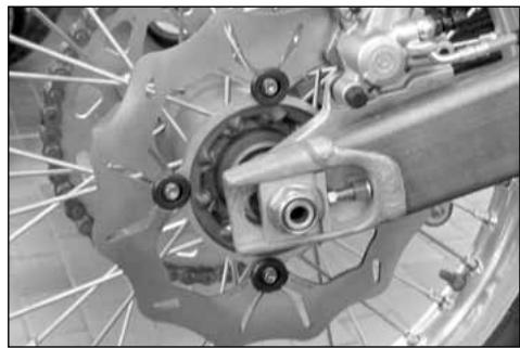
natural_image
Close-up of a bicycle brake system with visible components and suspension rings (no text or symbols)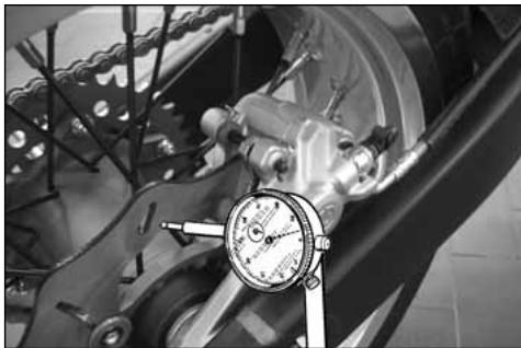
natural_image
Close-up of a mechanical assembly with a dial indicator and brake caliper (no visible text or symbols)DISC CLEANING
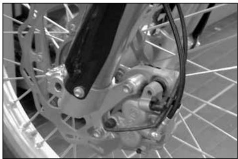
Poor braking can also be caused by oil on the disc. Oil or grease on the disc must be cleaned off with a high flash-point oil free solvent, such as acetone or lacquer thinner.
natural_image
Close-up of a bicycle wheel's head and dashboard assembly (no visible text or symbols)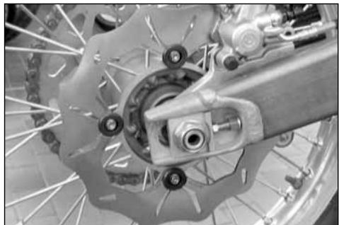
natural_image
Close-up of a bicycle brake system with visible components and suspension rings (no text or symbols)FLUID CHANGE
The brake fluid should be checked and changed in accordance with the Periodic Maintenance Chart or whenever it is contaminated with dirt or water. Don't change the fluid in the rain or when a strong wind is blowing.
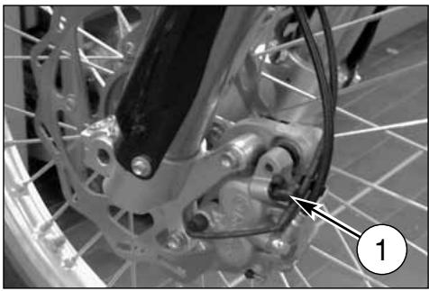
natural_image
Close-up of a bicycle wheel assembly with visible mechanical components and a numbered annotation (1) pointing to a specific part.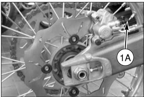
natural_image
Close-up of a bicycle wheel assembly with visible gears and brake calipers (no text or symbols)CAUTION!
* Use only brake fluid from a sealed container (DOT 4). Never use old brake fluid.
* Never allow contaminants (dirt, water, etc.) to enter the brake fluid reservoir.
* Don't leave the reservoir cap off any length of time to avoid moisture contamination of the fluid.
* Handle brake fluid with care because it can damage paint.
* Don't mix two types of fluid for use in the brake. This lowers the brake fluid boiling point and could cause the brake to be ineffective. It may also cause the rubber brake part to deteriorate.
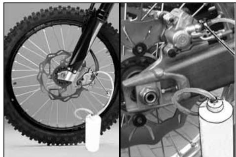
natural_image
Side-by-side comparison of a bicycle wheel and its internal mechanical components (no text or symbols visible)To replace the fluid, proceed as follows:
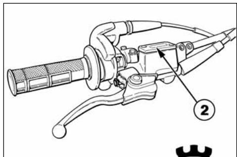
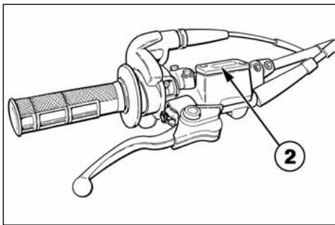
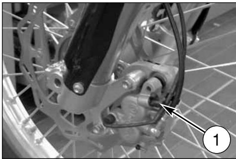
- Remove the rubber cap on the bleeding valve (1) or (1A).
- Attach a clear plastic hose to the bleeding valve on the brake caliper and turn the other end of the hose into a container.
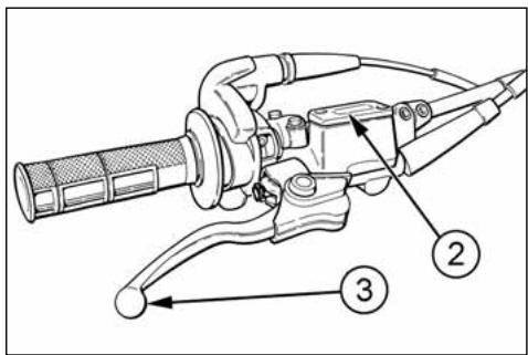
- Remove fluid reservoir cap (2) or (2A) and the rubber.
- Loosen bleeding valve on the brake caliper.
natural_image
Technical line drawing of a mechanical lever assembly with labeled component (no text or symbols present)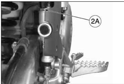
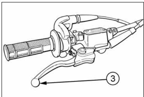
- Pump with brake lever (3) or brake pedal (3A) in order to push brake fluid out of line.
- Close the bleeding valve and fill the reservoir with fresh brake fluid.
- Open the bleeding valve, apply the brake using the brake lever or pedal, close the bleeding valve with the brake lever or pedal applied and then quickly release the lever or pedal.
- Repeat this operation until the brake line is filled and clear fluid starts coming out of the plastic hose: now close the bleeding valve.
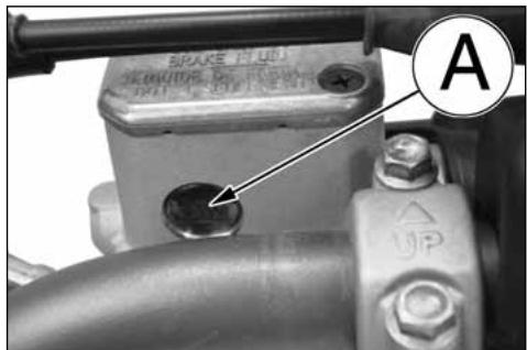
- Restore the brake fluid level (A) or (B) then reassemble the rubber and the fluid reservoir cap.
After the brake fluid replacement, it is necessary to operate the braking system bleeding (see pages 46 and 48).
natural_image
Technical line drawing of a mechanical tool with handle and lever (no text or symbols)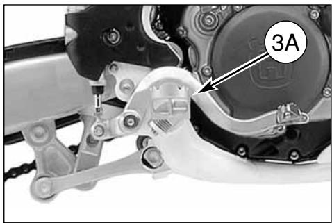
natural_image
Mechanical assembly diagram showing a motor and gear components with labeled part '3A' (no readable text or symbols beyond label)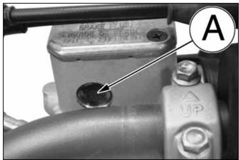
natural_image
Mechanical assembly diagram showing a valve and gear mechanism (no text or symbols)WARNING!
Brake fluid quickly ruins painted surfaces; any spilled fluid should be completely wiped up immediately.
* Brake fluid may cause irritation. Avoid contact with skin or eyes. In case of contact, flush thoroughly and call a doctor if your eyes were exposed.
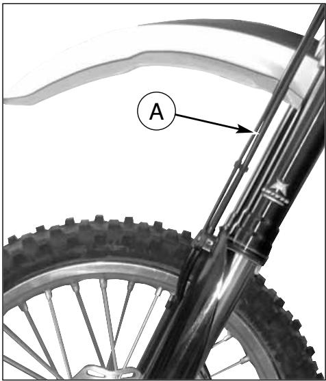
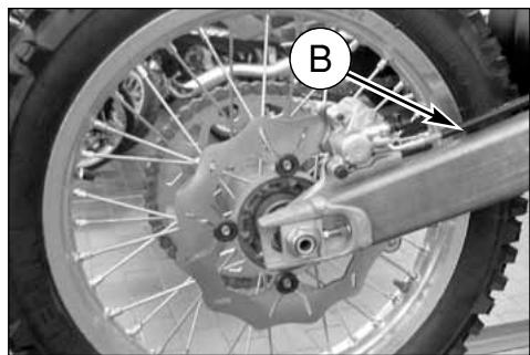
Periodically check the connecting hoses (see "Periodical maintenance card"): if the hoses (A) and (B) are worried or cracked, their replacement is advised.
natural_image
Close-up of a bicycle wheel with visible mechanical components and a labeled component 'B' (no text or symbols beyond label)The braking system must be bled after the fluid replacement or when, due to air in the circuit, the lever stroke is long and spongy.
Proceed as follows:
- Remove the rubber cap on the bleeding valve (1).
- Attach a clear plastic hose to the bleeding valve on the brake caliper and turn the other end of the hose into a container (make sure that the end of the hose is submerged in brake fluid during the entire bleeding operation).
natural_image
Close-up of a bicycle wheel assembly with visible mechanical components and a numbered annotation (1) pointing to a specific part.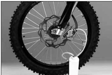
natural_image
Close-up of a bicycle wheel with visible tire, disc brake, and hub assembly (no text or symbols)- Remove fluid reservoir cap (2), the rubber and fill the reservoir with fresh brake fluid.
- Open the bleeding valve and pump with brake lever (3) several times until the fluid, clear and without bubbles, comes out of the hose: now close the bleeding valve.-
- Restore the brake fluid level (A) then reassemble the rubber and the fluid reservoir cap (2).
WARNING!
During the bleed operation the fluid level inside the reservoir must never be lower than the minimum level.
Tightening torque for bleed valve is 1,2 ÷ 1,6 kgm (12 ÷ 16 Nm; 8.8 ÷ 11.8 ft-lb).

As the braking fluid is a very corrosive substance, in the case it comes in contact with your eyes wash them abundantly with water.

During the bleeding of the braking circuit keep the handlebar turned leftwards. This is the way to lift the tank and to make easier the bleeding of braking system.

If the lever stroke gets stretchy and the braking action results as poor in the case of falls during competitions, er repair work in shops, repeat the ing operation described above.

As the bleeding operation does not fully eliminate the air inside the circuit, the small quantity of air remaining inside will be eliminated after time of use of the brake. In this cavever, the action of the lever will be and the stroke shorter.
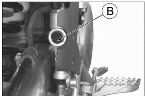
REAR BRAKING SYSTEM BLEEDING
The braking system must be bled after the fluid replacement or when, due to air in the circuit, the pedal stroke is long and spongy.
To bleed the system:
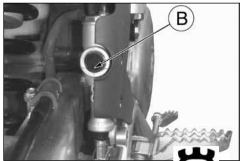
- Remove the reservoir cover (A) rubber boot (21 mm/0.83 in wrench) and top up with (DOT 4) brake fluid.
- Attach a clear plastic hose to the bleed valve (1) on the caliper and turn the other end of the hose into a container.
Depress the pedal (2) and keep it full down.
- Loosen the bleed union letting out fluid (at first, only air will come out), then, closing the union slightly.
- Release the pedal and wait for a few seconds before repeating the operation until only fluid come out of the tube.
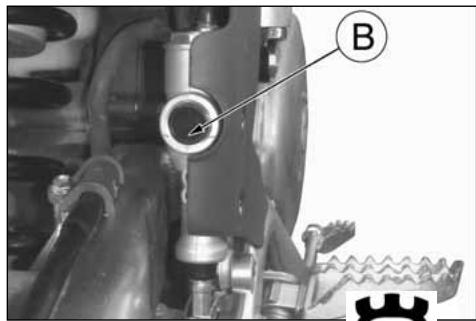
- Close the bleed union to the prescribed torque and check the fluid level (B) inside the reservoir before reassemble the cap (A). If the bleeding operation has been done correctly, the pedal will have no mushy feel. If not, repeat the operation.
NOTE
Should the motorcycle, due to a fall during a competition or shop repairs, show some elasticity of the brake lever stroke, with a subsequent braking efficiency decrease, you'll to repeat the circuit bleeding as above described.
natural_image
Mechanical assembly diagram showing a valve and gear mechanism (no text or symbols)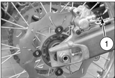
natural_image
Close-up of a bicycle brake system with visible components and a numbered label (1), no readable text or symbols present.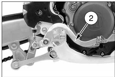
natural_image
Mechanical assembly diagram showing a motor and linkage mechanism (no text or symbols visible)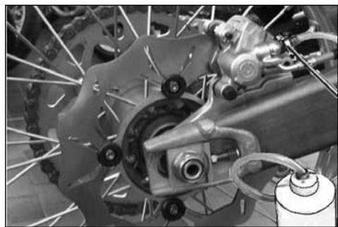
natural_image
Close-up of a bicycle brake system with visible components and suspension rings (no text or symbols)WARNING!
During the bleed operation the fluid level inside the reservoir must never be lower than the minimum level.
Tightening torque for bleed valve is 1,2 ÷ 1,6 kgm (12 ÷ 16 Nm; 8.8 ÷ 11.8 ft-lb).
natural_image
Mechanical assembly diagram showing a valve and gear mechanism (no text or symbols visible)EXHAUST MUFFLER
The muffler reduces the noise of the exhaust gases, but it is an integral part of the exhaust as well. As such, its conditions affect the motorcycle performance.
When the noise on the exhaust is too high, it means that the deadening material set on the holed tube inside the muffler is deteriorated.
WARNING: Check the deadening material after every competition and replace it if necessary.
REPLACING MUFFLER DEADENING MATERIAL
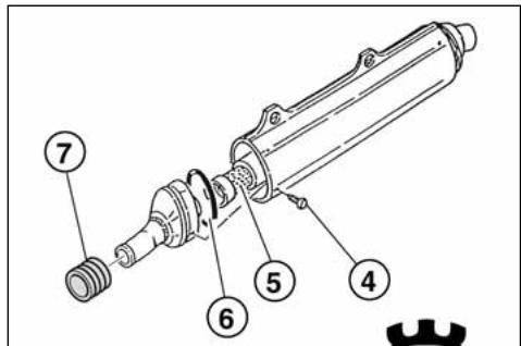
First turn counterclockwise fastening rear pin (A) then remove saddle, screws (1) and R.H. side panel (2). Remove the two exhaust silencer fastening screws (3). Extract the silencer from the union manifold to the
exhaust pipe. Remove the screws (4), the inner tube (5) and replace the old silencer packing. Check the
O-Ring (6) for wear and replace it, if necessary. Cheek the manifold (7) for wear and replace it, if necessary.
Note*: If silencer or exhaust are difficult to remove, help to slide them apart by tapping gently with a rubber or plastic hammer.
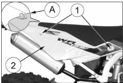
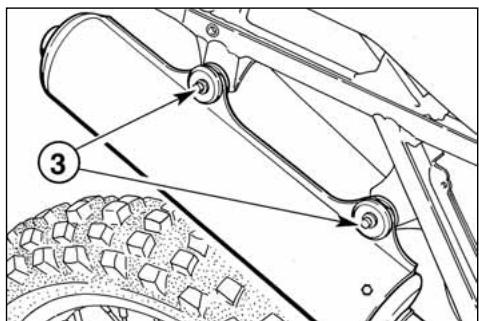
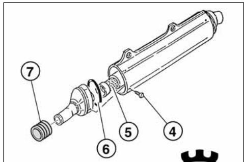
OVERHAULING THE WHEELS
The tables hereunder show the type of control the rim and wheel axle are to be submitted to.
Note*: if the rim is badly, it should be replaced.
DEFORMATION RIM
| STANDARD | MAX. LIMIT | |
| Side skid | less than 0,5 mm (0.02 in) | 2 mm (0,078 in) |
| Eccentricity | less than 0,8 mm (0.031 in) |
WHEEL SPOKES
Check to make sure that all the nipples are tight; tighten them if necessary.
Remember that an insufficient stretch jeopardizes the motorcycle stability.
For an instant check, use a metal point (for instance, a screw-driver) to beat the spokes with. A live sound accounts for an accurate tightening, while a dull sound means that a new tightening is necessary.
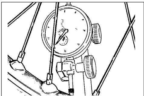
natural_image
Technical line drawing of a mechanical gauge or dial assembly with no visible text or symbolsWHEEL RIM AXLE BENDING
If the bending figure is over the allowable max. limit, straighten or replace the axle.
If the wheel axle cannot be straightened within the max. limit (0,2 mm/) stated, replace it.
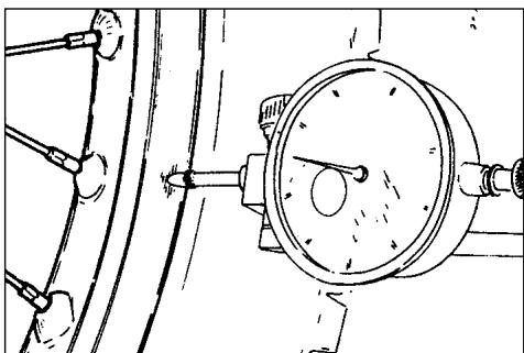
natural_image
Technical line drawing of a pressure gauge mounted on a mechanical component (no text or symbols)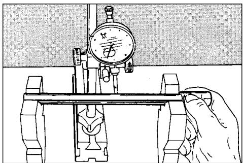
natural_image
Illustration of a hand operating a mechanical testing setup with a dial and clamped components (no text or symbols)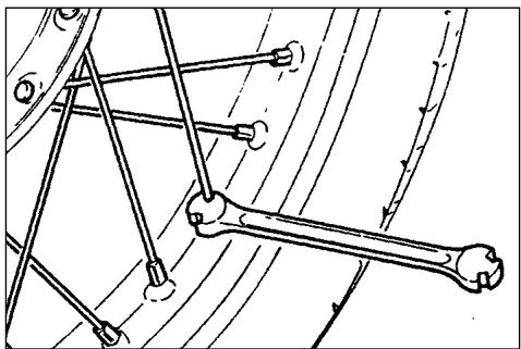
natural_image
Mechanical linkage diagram showing a bone and connecting rods (no text or labels)ELECTRICAL COMPONENTS LOCATION
The ignition system includes the following elements:
- Generator (1), in oil bath, on the inner side of L.H. crankcase cover;
- Electronic ignition coil (2) under the fuel tank (CR);
- Electronic power unit C.D.I. (3) fastened to the frame, in front of the engine (CR);
- Voltage regulator (4) fastened to the frame, under the fuel tank (WR);
- Spark plug (5) on the cylinder head;
- Electronic ignition coil /Electronic power unit C.D.I. (6; WR) under the fuel tank;
The electric system includes the following elements (WR):
- Flashing indicator device (7) under the fuel tank
- Headlamp (6) with two filaments bulb of 12V-35/35W and parking light bulb of 12V-5W;
- Back light (7) LED type;
- Turn signals bulb (8) of 12V-10W;
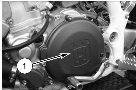
natural_image
Close-up of a mechanical assembly with a circular component and wiring, no visible text or symbols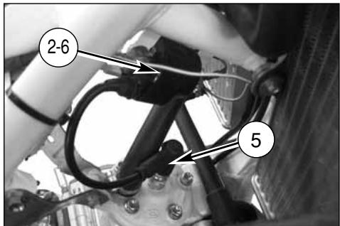
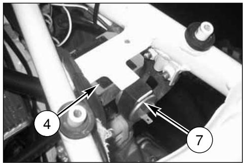
natural_image
Mechanical assembly diagram showing components labeled 4 and 7, with no readable text or symbols beyond labels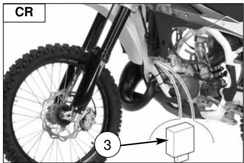
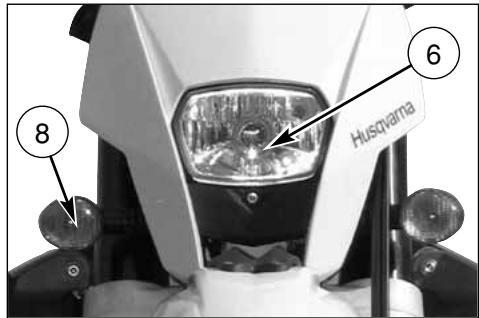
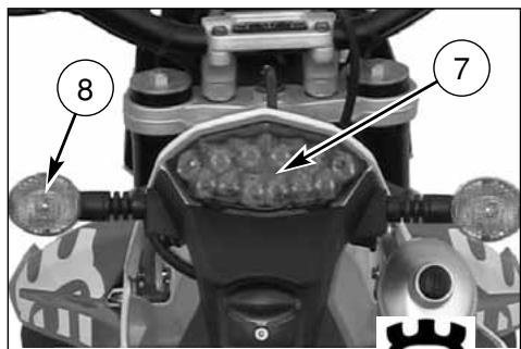
CABLE COLOUR CODING (CR)
| Bk-R | Black - Red |
| Bk-W | Black - White |
| Bk-Y | Black - yellow |
| Gr | Gray |
| R | Red |
| R-B | Red - White |
| W-BI | White - Blue |
KEY TO ELECTRIC DIAGRAM (CR)
- Electronic power unit
- Alternator
- Spark plug
- H.T. coil
- Engine stop button
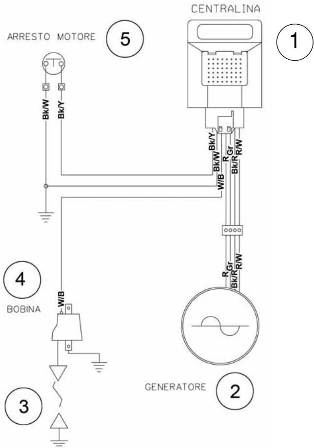
CABLE COLOUR CODING (WR)
| B | Blue |
| Bk | Black |
| Br | Brown |
| G | Green |
| Gr | Grey |
| O | Orange |
| Pk | Pink |
| R | Reda |
| Sb | Sky blue |
| V | Violet |
| W | White |
| Y | Yellow |
KEY TO ELECTRIC DIAGRAM (WR)
A. Front headlamp
B. R.H. front turn indicator
C. L.H. front turn indicator
D. L.H. commutator
E. Horn
F. Rear stop switch
G. Front stop switch
H. Voltage regulator
I. Alternator
L. Turn indicators flasher
M. Electronic ignition coil/Electronic power unit C.D.I.
N. Spark plug
O. R.H. rear turn indicator
P. L.H. rear turn indicator
Q. Tail light
R. Instrument
S. Side light
U. Plate illumination
V. Speed sensor
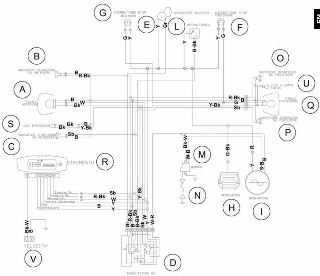
HEADLAMP BULBS REPLACEMENT (WR)
To gain access to the healamp bulbs, proceed as follows:
- remove the upper fastening screw of the the headlamp carrier to the instrument panuel support (A);
- push forward the headlamp carrier (B) and pull it towards the high (C) in order to uncouple from the two lower supports.
-
remove the headlamp carrier;
-
remove the two filaments bulb (7) connector (2) and the boot (3);
- remove the screw (6);
- release the bulb holding spring (4) and then the bulb itself.
To replace the parking light bulb (5) extract it from the inside cover.
After replacement, reverse operations for reassembly.
TAIL LIGHT (WR)
The back light is a LED light.
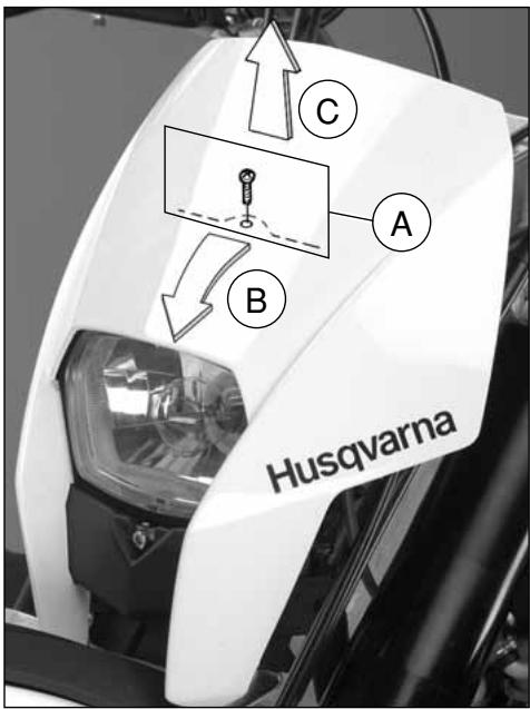
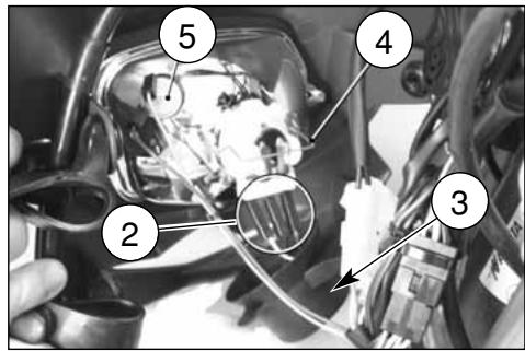
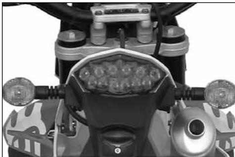
natural_image
Top-down view of a motorcycle's front wheel and dashboard (no visible text or symbols)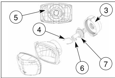
REPLACING THE NUMBER PLATE LAMP (WR)
Pull out the number plate lampholder (4) from the back of the vehicle. Pull out the lampholder and the bulb. Rotate the bulb (5) to remove from the lampholder.
Once the bulb has been replaced, reverse the above procedure.
ADJUSTMENT OF HEADLIGHT (WR)
When checking the proper orienting of headlight, inflate tires at right pressure, sat a person on the saddle and place the motorcycle perpendicular with its longitudinal axis 10 meter (33 ft) from a wall or screen. Then trace an horizontal line equal to the height of headlight center and a vertical one in line with its longitudinal axis.
Adjust the preadlamp aiming by turning screw (1) to lower or lift the high beam.
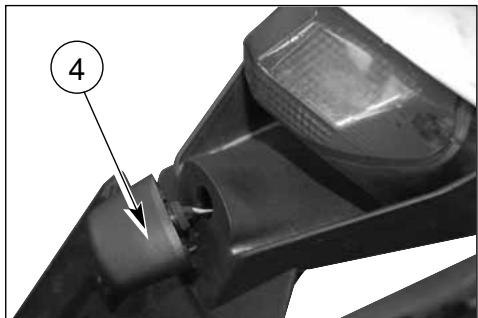
natural_image
Close-up of a mechanical component with a numbered annotation (4) pointing to a small feature, no readable text or symbols present.If possible, execute this operation in a shadowy place. When the low beam is on, the upper boundary limit between dark and lit zone should be 9/10 th of headlight center from groud.
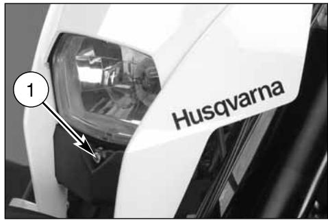
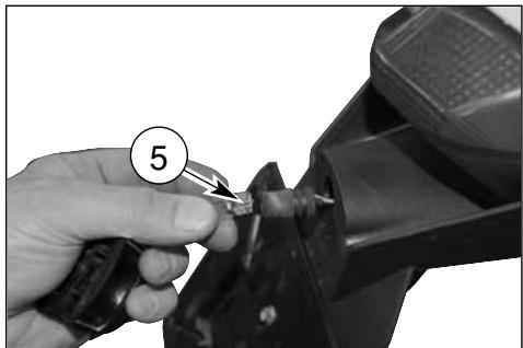
natural_image
Close-up of a hand using a tool to cut a mechanical component, no visible text or symbols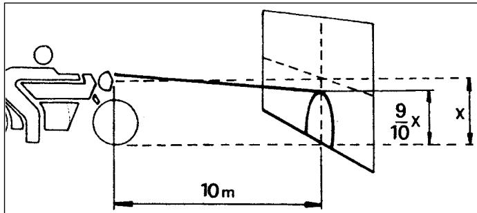
EQUIPMENT
| Pos. | Code Nr. | NAME | MODEL |
| 1 | 8000H1554 | MULTILANGUAGE QUICK MANUAL (1) | WR-CR |
| 2 | 8A0065437 | L.H. REARVIEW MIRROR (1) | WR |
| 8B0065437 | R.H. REARVIEW MIRROR (1) | WR | |
| 3 | 800097615 | HUSQVARNA KEY HOLDER (1) | WR |
| 4 | 8000H1581 | BLINKERS KIT (1) | WR |
| 5 | 80A0A6210 | HAND GUARDS KIT (1) | WR |
| 6 | 8000H2123 | “USB” MEMORY (1) | WR-CR |
| 7 | 8000H0120 | ENGINE GUARD (1) | WR-CR |
| 8 | 800074016 | SIDE STAND (1) | CR |
| 9 | 8000B1530 | HOOK KIT FOR RACE STARTING (1) | CR |
| 10 | 8000H0791 | KIT CARBURETOR JETS(1) | CR |
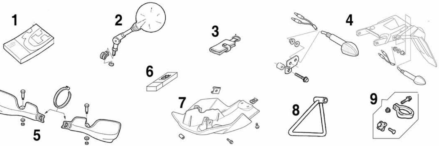
OPTIONAL PARTS LIST
| Pos. | N. Codice | NAME | MODELS |
| 1* | 8C0096837 | REAR SPROCKET Z=49 (1) | WR-CR |
| 8E0096837 | REAR SPROCKET Z=51 (1) | WR-CR | |
| 8F0096837 | REAR SPROCKET Z=52 (1) | WR-CR | |
| 2* | 800082469 | DRIVE SPROCKET Z=12 (1) | WR-CR |
| 8B0082469 | DRIVE SPROCKET Z=14 (1) | WR-CR | |
| 8C0082496 | DRIVE SPROCKET Z=15 (1) | WR-CR | |
| 3 | 8000A8986 | ENGINE GASKET KIT (1) | WR-CR |
| 4 | 800094852 | ENGINE SEALS KIT (1) | WR-CR |
| 5* | 8000H0119 | EXHAUST PIPE (1) | WR |
| 6* | 800092788 | SILENCER SLEEVE (1) | WR |
| 7* | 8000H0052 | CARBURETOR KIT (1) | WR |
| 8* | 8000H0791 | CARBURETOR JETS KIT (1) | WR-CR |
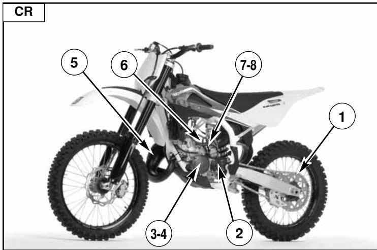
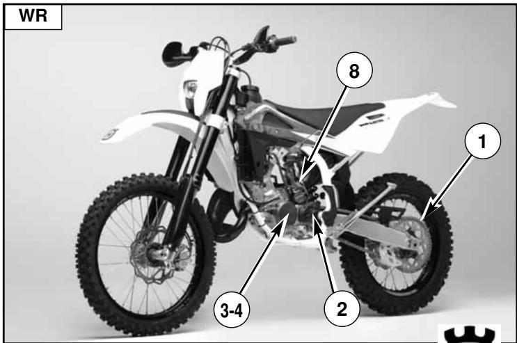
*: For racing only on WR
APPENDIX
AFTER-RACE CHECK POINTS
After racing, first clean the motorcycle and then inspect the entire motorcycle, with special attention to the items listed in «MAINTENANCE» table (Appendix A), such as the air cleaner, carburetor, brakes, etc.
Carry out general lubrication, and make adjustment as necessary.
STORAGE
When the motorcycle is to be stored for any length of time, is should be prepared for storage as follows:
- Clean the entire motorcycle thoroughly.
- Empty the fuel from the fuel tank, and empty the carburetor float bowl. (If left in for a long time, the fuel will deteriorate).
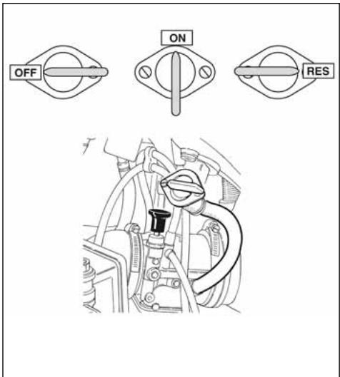
WARNING
Never litter the environment with fuel, and let the engine running in open air, never in closed rooms.
- Lubricate the drive chain and all the cables.
- Spray oil on all unpainted metal surfaces to prevent rusting. Avoid getting oil on rubber parts or in the brakes.
- Set the motorcycle on a box or stand so that both wheels are raised off the ground. (If this cannot be done, put boards under the front and rear wheels to keep dampness away from the tire rubber).
- Tie a plastic bag over the exhaust pipe to prevent moisture from entering.
- Put a cover over the motorcycle to keep dust and dirt from collecting on it.
To put the motorcycle back into the use after storage.
- Make sure the spark plug is tight.
- Fill the fuel tank.
- Run the engine for about 5 minutes to warm the oil then drain the oil.
- Put in fresh transmission oil (page 19).
- Check all the points listed under the inspection and Adjustment Section (Appendix A).
- Lubricate the points (listed in the Lubrication Section (Appendix A).
CLEANING
IMPORTANT RECOMMENDATION
Premised that, before the motorcycle washing, it is necessary to protect opportunely from the water the following parts:
a) Rear opening of the muffler;
b) Clutch and brake levers, hand grips, handlebar commutators;
c) Air cleaner intake;
d) Fork head, wheel bearings;
e) Rear suspension links.
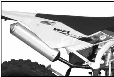
natural_image
Close-up of a white off-road vehicle's rear suspension system with visible tire tracks and mechanical components (no text or symbols)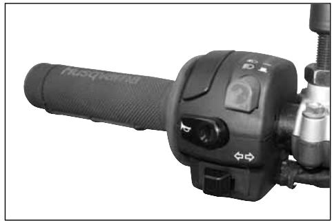
natural_image
Close-up of a black automotive hand crank with control buttons and lever (no visible text or symbols)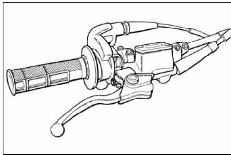
natural_image
Line drawing of a mechanical tool with handle and lever (no text or symbols)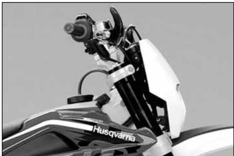
natural_image
Close-up of a motorcycle's front view showing the engine and cockpit (no visible text or symbols)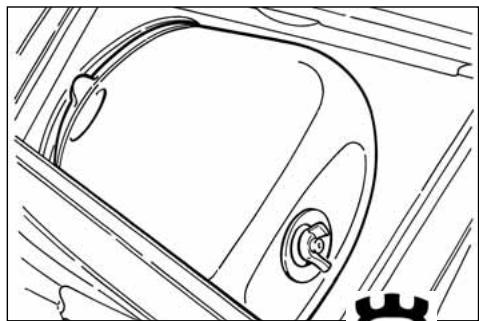
natural_image
Line drawing of a car's front wheel and side door (no text or symbols)it is necessary ABSOLUTELY TO AVOID THAT HIGH PRESSURE JETS OF WATER OR AIR come to contact with THE ELECTRICAL PARTS, especially the electronic control unit (1).
After washing:
- Lubricate the points listed in the Maintenance Table (Appendix A).
- Start the engine and run it for 5 minutes.
- Test the brakes before riding the motorcycle.
WARNING*: Never wax or lubricate the brake disc. Loss of braking and an accident could result. Clean the disc with an oilless solvent such as acetone. Observe the solvent warnings.
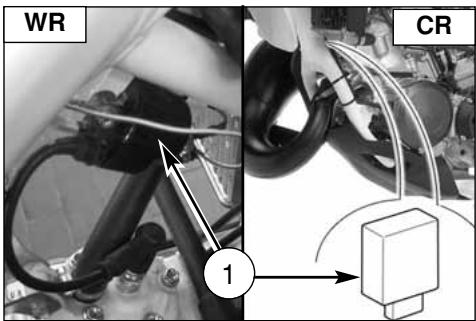
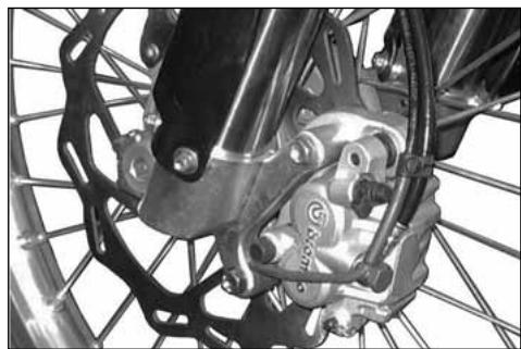
natural_image
Close-up of a bicycle's front wheel and brake system with visible springs and hub (no text or symbols)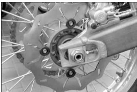
natural_image
Close-up of a bicycle brake system with visible components and wheel rim (no text or symbols)PRE -DELIVERY INSPECTION
| Description | Operation | Pre-delivery | Description | Operation | Pre-delivery |
| Engine oil | Check level | □ | Tyres | Check pressure | □ |
| Two-stroke mix oil level | Check level | □ * | Side stand | Check operation | □ |
| Coolant | Check / Restore level | □ | Side stand switch | Check operation | □ |
| Cooling system | Check for leakage | □ | Electrical equipment | Check operation | □ |
| Electric fans | Check operation | □ * * | Instrument panel | Check operation | □ |
| Spark plugs | Check / Replace | □ | Lights / Visual signals | Check operation | □ |
| Throttle body / Carburettor | Check and adjust | □ | Horn | Check operation | □ |
| Brakes / Clutch fluid | Check level | □ | Headlight | Check operation | □ |
| Brakes / Clutch | Check operation | □ | Ignition switch | Check operation | □ |
| Brakes / Clutch | Check lines for leakage | □ | Locks | Check operation | □ |
| Throttle control | Check operation | □ | Screws and nuts | Check / Tighten | □ |
| Throttle control | Check / Adjust play | □ | Hose clamps | Check / Tighten | □ |
| Choke control | Check operation | □ | General lubrication | □ | |
| Flexible controls and transm. | Check / Adjust | □ | General test | □ | |
| Drive chain | Check / Adjust | □ |
※ : only for motorcycles with 2 stroke engine
**: only for some models
NOTES FOR USA/CDN MODEL
DISCLAIMER OF WARRANTY
IN ACCEPTING DELIVERY OF THIS MOTORCYCLE THE BUYER OR TRANSFEREE ACKNOWLEDGES THAT HE HAS THOROUGHLY INSPECTED THE MOTORCYCLE, AND FURTHER AGREES TO ACCEPT THE MOTORCYCLE AS IS WITH ALL DEFECTS OR FAULTS, CONCEALED OR OBVIOUS. HE FURTHER AGREES THAT NO WARRANTIES ATTACH, EXPRESS OR IMPLIED, INCLUDING ANY WARRANTY OF MERCHANTABILITY OR FITNESS FOR ANY PARTICULAR PURPOSE. THE BUYER OR TRANSFEREE INDEMNIFIES AND HOLDS HARMLESS HUSQVARNA MOTORCYCLES S.R.L., ITS AGENTS AND EMPLOYEES. FOR ANY FAILURE OF PERFORMANCE, COST OF SERVICE, OR REPAIR. TC-TXC: THE BUYER FURTHER ACKNOWLEDGES THAT THIS MOTORCYCLE IS NOT INTENDED FOR USE ON PUBLIC STREETS, ROADS, HIGHWAYS, OR TRAILS UNDER PUBLIC JURISDICTION AND THAT USE ON SUCH MAY VIOLATE STATE AND FEDERAL LAW.
Noise emission warranty
HUSQVARNA MOTORCYCLES S.R.L.. warrants that this exhaust system, at the time of sale, meets all applicable U.S. EPA Federal noise standards. This warranty extends to the first person who buys this exhaust system for purposes other than resale, and to all subsequent buyers.
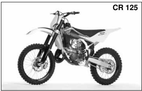
natural_image
Black and white photo of a CR 125 motorcycle with visible dynamics and wheels (no text or symbols on the bike body)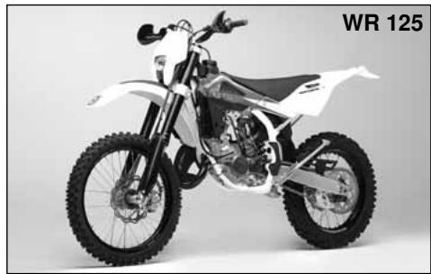
natural_image
Side view of a white and black off-road motorcycle with visible tracks and wheels (no text or symbols)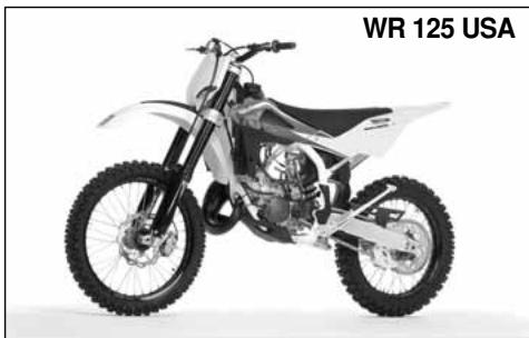
natural_image
Black and white photo of a white and silver off-road motorcycle with visible dynamics and wheels (no text or symbols)SPARK ARRESTER
The WR models are equipped with a U.S. Forest Service approved spark arrester for maximum efficiency and performance.
"SPARK ARRESTER" MAINTENANCE AND CLEANOUT INSTRUCTIONS
Proceed as follows:
A: First turn counterclockwise fastening rear pin (A) then remove saddle, screws (1) and R.H. side panel (2).
B: Remove the two screws (3) fastening the muffler to the rear frame. Extract the silencer from the union manifold to the exhaust pipe.
Note*: If silencer or exhaust are difficult to remove, help to slide them apart by tapping gently with a rubber or plastic hammer.
C: remove the four screws (4) and the endcap (5) from silencer's body;
D: examine SPARK ARRESTER conditions and remove, if necessary, carbon particles from the SPARK ARRESTER screen;
E: if necessary, inflate air on the SPARK ARRESTER screen, in the opposite direction in respect of the exhausted gas flow;
F: assemble the front endcap on the silencer's body, mounting the screws in the correct position, providing a tight connection between endcap and silencer's body, using, if necessary, a silicone paste;
G: re-assemble the silencer on motorbike.
Due to the SPARK ARRESTER position on the silencer, if you need only to check the SPARK ARRESTER conditions you can:
A: disassemble the silencer from motorbike;
B: check SPARK ARRESTER conditions simply looking into the silencer from front endcap opening;
C: if the check is positive, you can proceed in re-assembling the silencer on the motorbike;
D: if the check is negative, proceed with the maintenance and cleanout procedure.
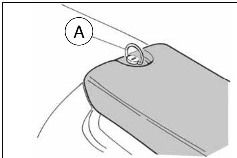
natural_image
Diagram of a mechanical component with labeled section A, showing motion lines and a circular marker (no text or symbols beyond label)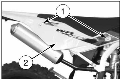
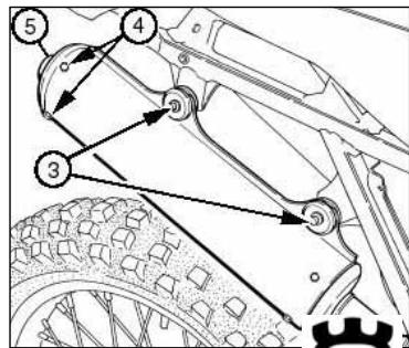
ALPHABETIC INDEX
Page
A
Adjusting the carburetor 21
Adjusting the clutch 22
Adjusting the driven transmission 33
Adjusting the fork 29
Adjusting the front brake control lever 26
Adjusting the headlamp....56
Adjusting the idle 21
Adjusting the rear brake idle stroke 27
Adjusting shock absorber hydraulic brake 32
Adjusting shock absorber preload spring....31
Adjusting the rear brake pedal position 27
Adjusting the steering bearing play 25
Adjusting the suspensions according
to the track special conditions 28
Adjusting the throttle cable 21
B
Brakes....39
Brake disc cleaning 43
Brake disc warpage 42
Brake disc wear....42
Brake pad assembly 41
Brake pad wear 40
Brake pad disassembly 40
C
Carburettor 7
Carburetor starter 10
Chain lubrication....34
Checks after every competition 58
Checks during running in....16
Check of air filter 24
Check of chain, pinion, crown wear 34
Check of cooling fluid level 19
Check of front brake fluid level 26
Check of rear brake fluid level 27
Check of transmission oil level 19
Cleaning the air filter 24
Clutch 7
Clutch control 14
Coolant replacement 20
Cooling fluid 8
Control position....6
D
Digital instrument 11
Driven transmission chain 7
E
Electric diagram 52,53
Electric elements 51
Engine lubrication 8
Engine start 17
Engine stop 18
F
Filling the braking system 44
Fluid change 44
Fork oil level 29
Fuel....10
Fuel cock 10
Front brake control 13
Front braking system bleeding 46,47
Front fork 7
G
Gearbox control....15
Gearbox outlet pinion 7
General cleaning....59
H
Handlebar commutator 14
Handlebar position change 30
Headlamp bulbs replacement 54
|
Ignition 7
Important notice ....3
L
Lamp light plate replacement ....55
Long inactivity 58
M
Motorcycle stop 18
Muffler on the exhaust 49
0
Overhauling the wheels....50
P
Pad cleaning 41
Parts replacement ....3
Pilot lights....11
Preliminary checks 16
R
Rear brake control....14
Rear braking system bleeding 48
Rear damper 7
Rear pinion 7
Rear taillight bulb replacement 55
Removing the front wheel 36
Removing the rear wheel 38
Running in 16
S
Steering lock 13
Side stand 9
Spark arrester 63
Spark plug 7
Spark plug check....23
T
Throttle control 13
Tires....8,39
Transmission oil change....19
V
Vehicle identification number 5
Voltage regulator....23
W
Wheel pin bending 50
Wheel spokes 50
Wheels 8,36
FRANÇAIS
H
Husqvarna
PRESENTATION
natural_image
Side profile of a white and black off-road motorcycle with visible tracks and wheels (no text or symbols)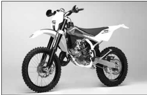
natural_image
Side profile of a white and black off-road motorcycle with visible tracks and wheels (no text or symbols)MOTOCROSS
natural_image
Black-and-white photo of a motorcyclist mid-jump, wearing helmet and gear (no visible text or symbols)ENDURO
natural_image
Black-and-white photo of a dirter mid-jump on a motorcycle in a mountainous outdoor field (no visible text or symbols)IMPORTANT
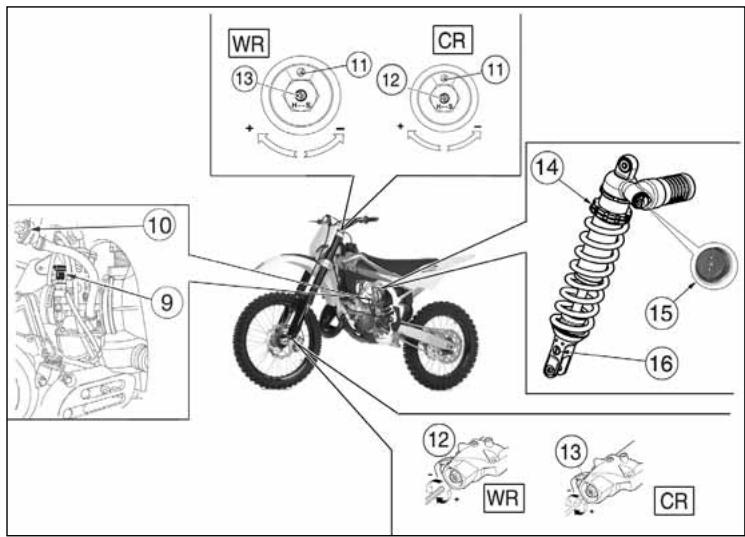
DONNEES TECHNIQUES
MOTEUR
Gicleur principal (CR) .....460
Gicleur principal (WR) .....380
Gicleur ralenti (CR) 35
Soupape gaz (CR) 4,0
Soupape gaz (WR) 5,0
Epingle conique ....6BFY43
DIMENSIONS, POIDS, CAPACITE
CARBURANT
natural_image
Close-up of a mechanical component with labeled parts (no readable text or symbols)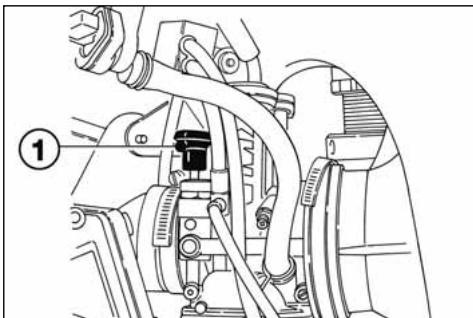
natural_image
Mechanical assembly diagram showing hoses and components (no text or labels)INSTRUMENT DIGITAL, VOYANTS (WR)
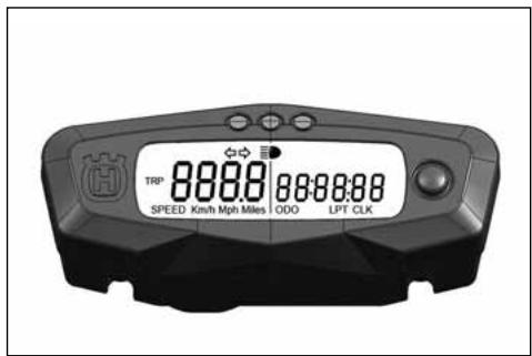
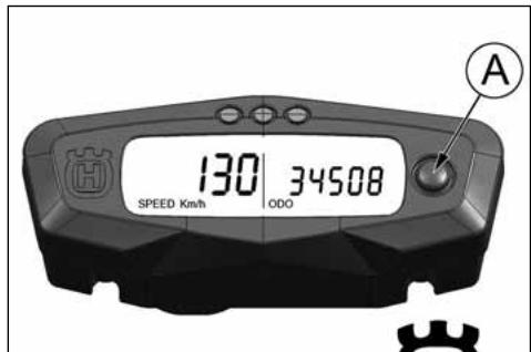
2- SPEED / CLOCK (figure 2)
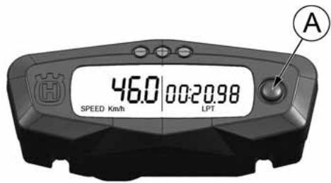
POIGNEE DES GAZ
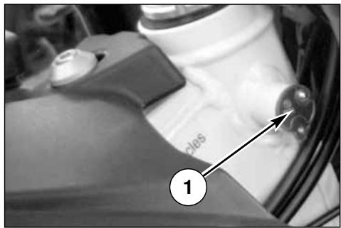
COMMUTATEUR GAUCHE SUR LE GUIDON (WR)
BOUTON D'ARRET MOTEUR (CR)
natural_image
Technical line drawing of a mechanical clamp or tool with a meshed cylindrical component and labeled part (1), no text or symbols present.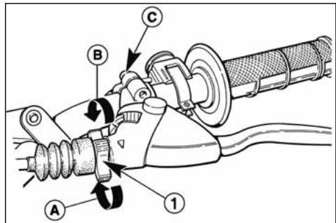
ATTENTION
natural_image
Mechanical assembly diagram showing a motor and linkage mechanism (no text or symbols visible)COMMANDE DU CHANGEMENT DE VITESSES
natural_image
Mechanical assembly diagram showing gear and components without any text or symbolsMODE D'EMPLOI DE LA MOTO
CONTROLES PRELIMINAIRES
ATTENTION!
natural_image
Technical line drawing of a mechanical assembly with no visible text or symbols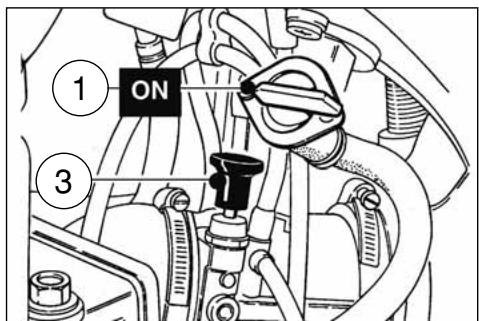
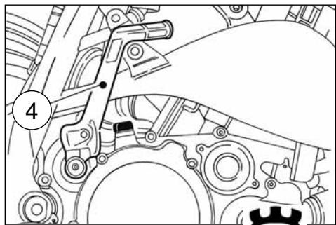
natural_image
Mechanical assembly diagram showing gear and shaft components (no text or labels)ARRET DU MOTOCYCLE ET DU MOTEUR
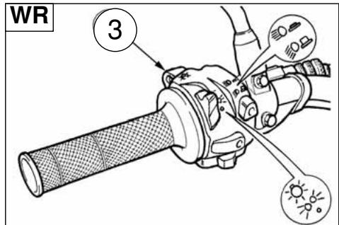
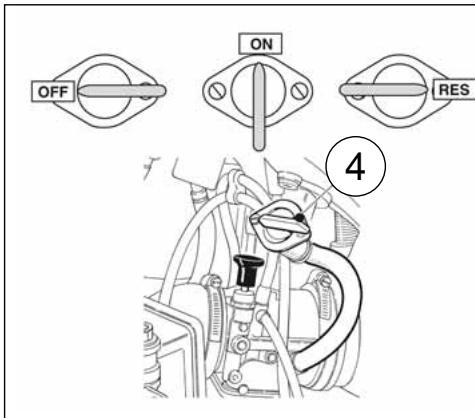
CONTROLE DU NIVEAU D'HUILE DU BOITE DE VITESSE
natural_image
Technical line drawing of a mechanical assembly with no visible text or symbols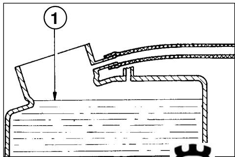
SUBSTITUTION DU LIQUIDE DE REFROIDISSEMENT

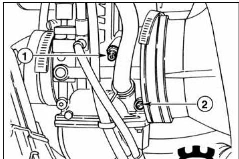
REGLAGE DE L'EMBRAYAGE
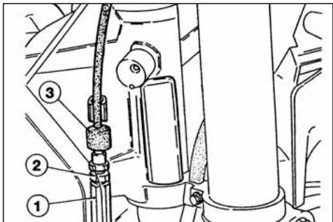
CONTROLE DE LA BOUGIE D'ALLUMAGE
natural_image
Technical line drawing of a spark plug with threaded end and shaft (no text or symbols)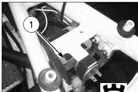
natural_image
Close-up of mechanical components with numbered annotation (1) and a gear icon, no readable text or symbols present.CONTROLE FILTRE A AIR
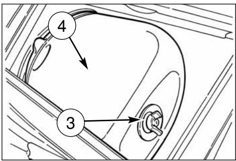
NETTOYAGE FILTRE A AIR
natural_image
Side view of a black-and-white photo of a motorcycle's front wheel and side-mounted disc, showing tire alignment (no text or symbols)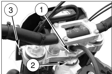
REGLAGE DU LEVIER DU FREIN AVANT ET CONTRÔLE DU NIVEAU FLUIDE FREIN AVANT
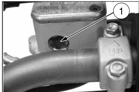
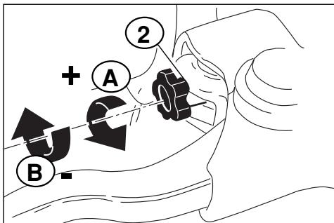
REGLAGE POSITION PEDALE FREIN ARRIERE
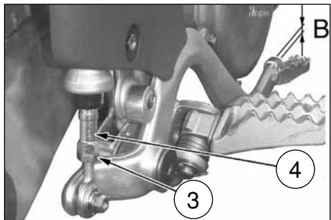
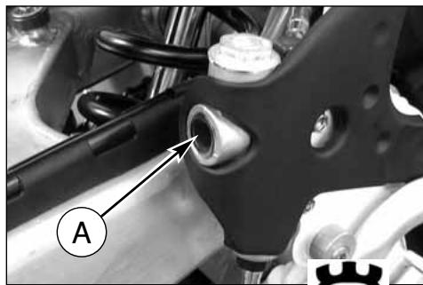
natural_image
Mechanical assembly diagram showing a bracket with labeled component A (no text or symbols beyond label)REGLAGE DES SUSPENSION PAR RAPPORT AUX CONDITIONS DE LA PISTE
natural_image
Black-and-white photo of a motorcyclist riding a dirt bike across a dusty terrain under cloudy skies (no text or symbols visible)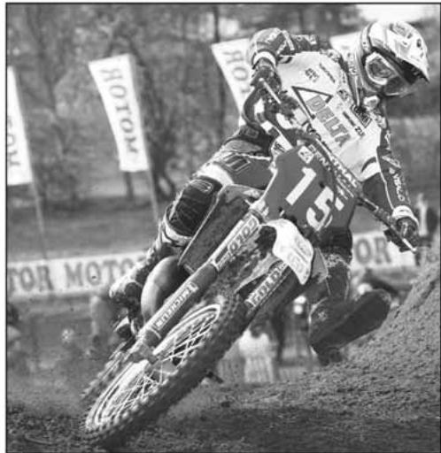
natural_image
Black-and-white photo of a dirter in action on a dirt track, wearing helmet and racing gear, with 'ROTOM' banners visible in background (no readable text on rider or equipment)Tarage standard: -9 clicks (CR)
Tarage standard: -10 clicks (WR)
Tarage standard: -13 clicks (CR)
Tarage standard: -10 clicks (WR)
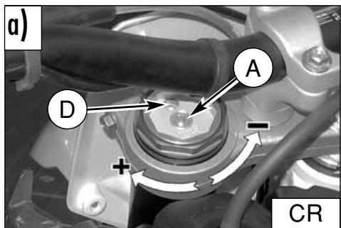
NIVEAU D'HUILE DE LA FOURCHE
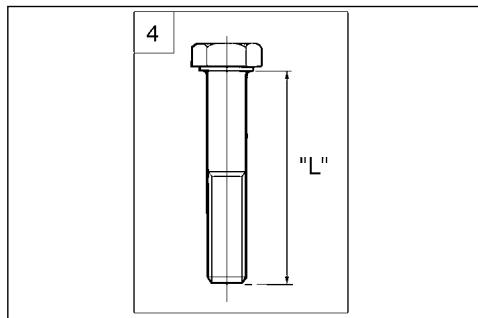
natural_image
Diagram of a mechanical component with a circular ring and labeled part 1 (no text or symbols beyond label)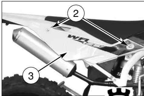
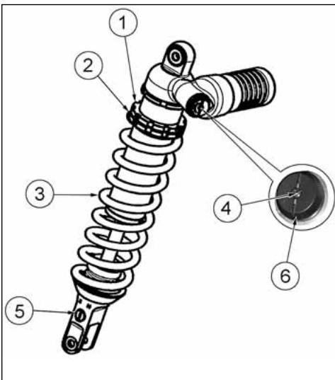
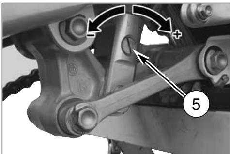
natural_image
Mechanical assembly diagram showing linkage components with arrows indicating motion (no text or symbols)CONTROLE USURE CHAINE, PIGNON ET COURONNE
Agir comme suit:
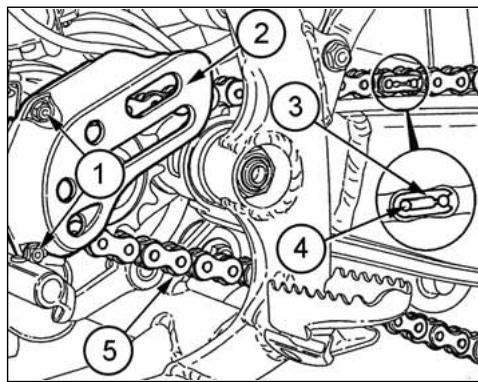
natural_image
Close-up of a black-and-white photo of a motor with visible wheel, suspension, and gear mechanism (no text or symbols)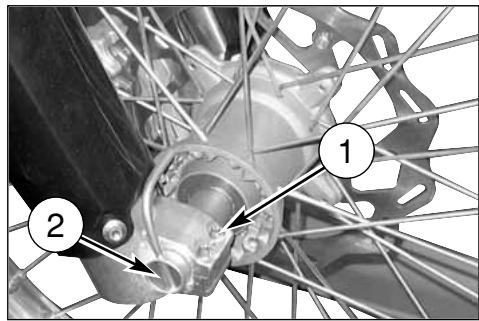
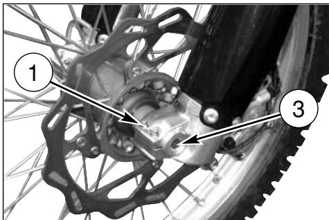
RÉMONTAGE DE LA ROUE AVANT
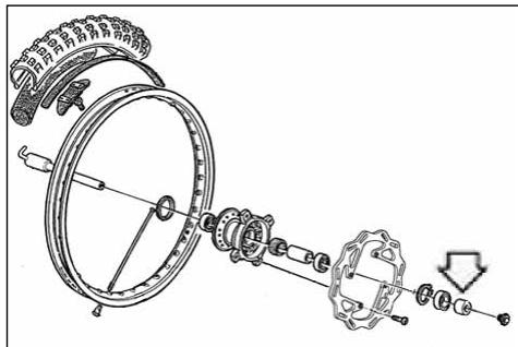
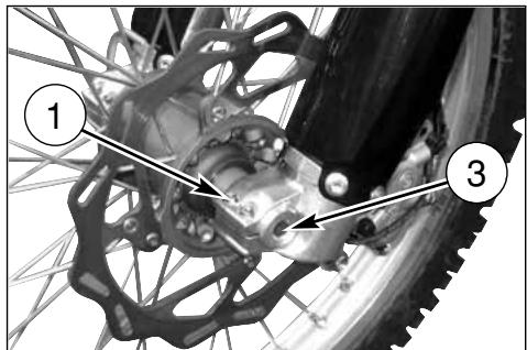
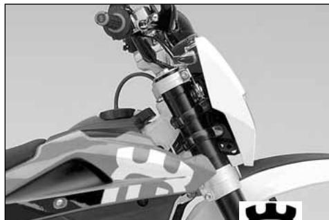
natural_image
Close-up of a motorcycle's front wheel and suspension system (no visible text or symbols)DÉMONTAGE DE LA ROUE ARRIÈRE

PNEUS
natural_image
Top-down view of a bicycle wheel with visible tire, disc, and hub (no text or symbols)FREIN
natural_image
Technical line drawing of a mechanical pressure gauge mounted on a structural frame (no text or symbols)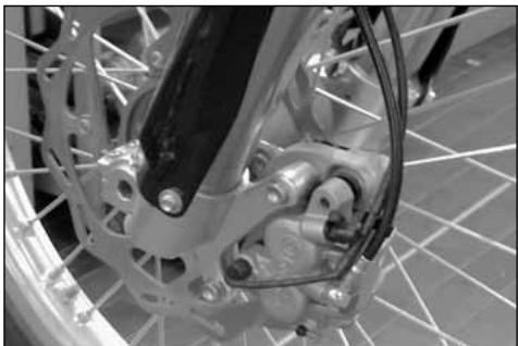
natural_image
Close-up of a bicycle's front wheel and brake system (no visible text or symbols)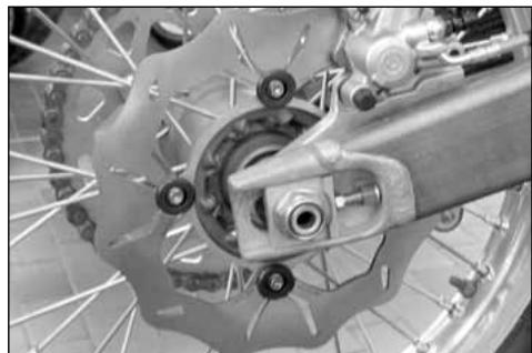
natural_image
Close-up of a bicycle wheel assembly with visible brake calipers and suspension components (no text or symbols)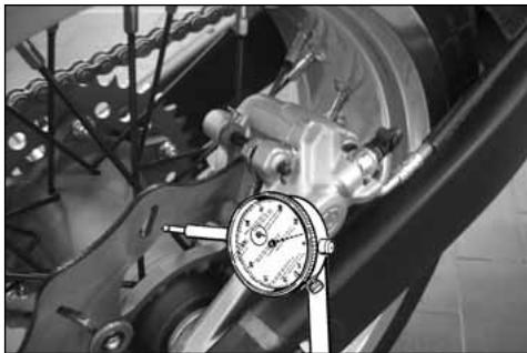
natural_image
Close-up of a mechanical assembly with a dial indicator and brake caliper (no visible text or symbols)NETTOYAGE DU DISQUE
natural_image
Close-up of a bicycle wheel's head and dashboard assembly (no visible text or symbols)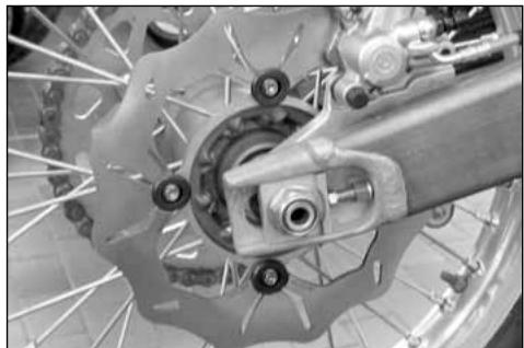
natural_image
Close-up of a bicycle brake system with visible components and wheel rim (no text or symbols)REPLACEMENT DU FLUIDE
natural_image
Close-up of a bicycle wheel assembly with visible mechanical components and a numbered annotation (1) pointing to a specific part.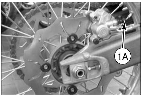
natural_image
Close-up of a bicycle wheel assembly with visible gears and brake calipers (no text or symbols)ATTENTION!
natural_image
Two-panel image showing a bicycle wheel and its internal mechanical components (no text or symbols visible)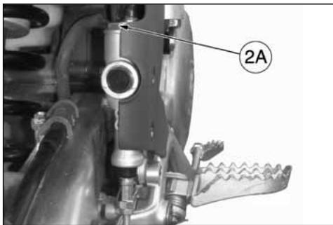
natural_image
Technical line drawing of a mechanical tool with handle and lever (no text or symbols)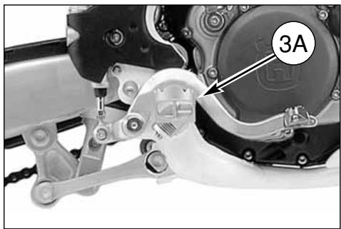
natural_image
Mechanical assembly diagram showing a motor and gear components with labeled part '3A' (no readable text or symbols beyond label)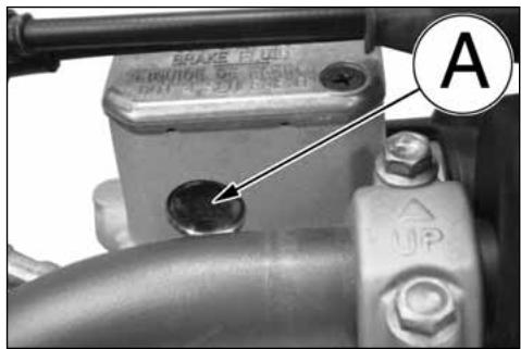
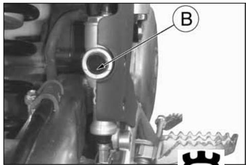
natural_image
Mechanical assembly diagram showing a valve and gear mechanism (no text or symbols)ATTENTION!
natural_image
Close-up of a bicycle wheel with visible tire, brake caliper, and mechanical components (no text or symbols)CURAGE INSTALLATION DE FREINAGE AVANT
natural_image
Close-up of a bicycle wheel assembly with visible mechanical components and a numbered annotation (1) pointing to a specific part.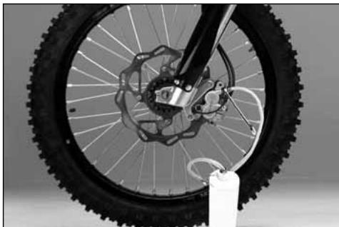
natural_image
Close-up of a bicycle wheel with visible tire, disc brake, and hub assembly (no text or symbols)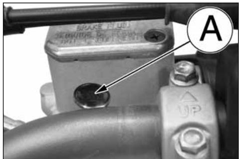
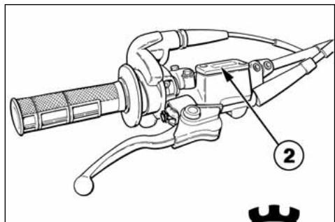
CURAGE DU SYSTEME DE FREINAGE ARRIERE
natural_image
Mechanical component diagram showing a valve assembly with labeled point A (no text or symbols beyond label)
natural_image
Mechanical assembly diagram showing a motor and gear mechanism with labeled component (no readable text or symbols)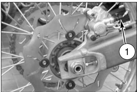
natural_image
Close-up of a bicycle brake system with visible components and a numbered label (1), no readable text or symbols present.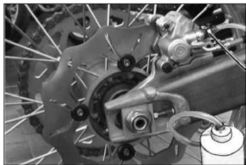
natural_image
Close-up of a bicycle brake system with visible components and suspension rings (no text or symbols)ATTENTION!
natural_image
Mechanical assembly diagram showing a valve or pump component with labeled part B (no text or symbols beyond label)SILENCIEUX D'ECHAPPEMENT
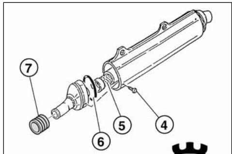
REVISION DES ROUES
natural_image
Technical line drawing of a mechanical gauge or dial assembly with no visible text or symbolsCOURBURE PIVOT ROUE
natural_image
Technical line drawing of a pressure gauge mounted on a mechanical component (no text or symbols)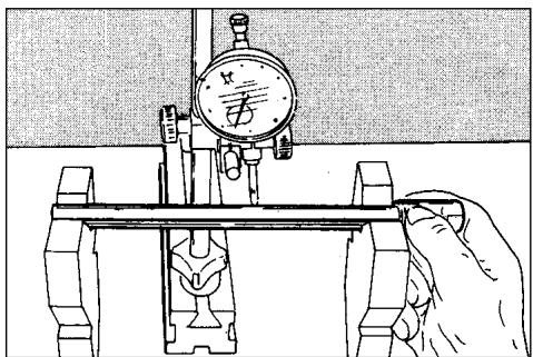
natural_image
Illustration of a hand operating a mechanical testing setup with a dial and clamped components (no text or symbols)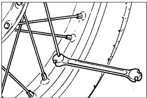
natural_image
Mechanical linkage diagram showing a bone and connecting rods (no text or labels)POSITION COMPOSANTS ÉLECTRIQUES
natural_image
Close-up of a mechanical assembly with a circular component and wiring, no visible text or symbols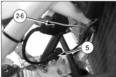
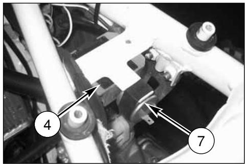
natural_image
Mechanical assembly diagram showing components labeled 4 and 7, with no readable text or symbols beyond labels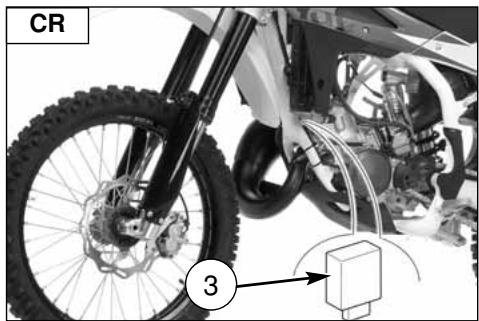
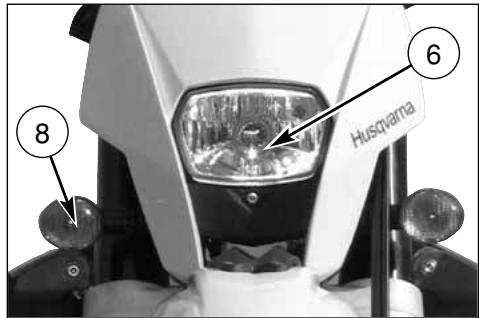
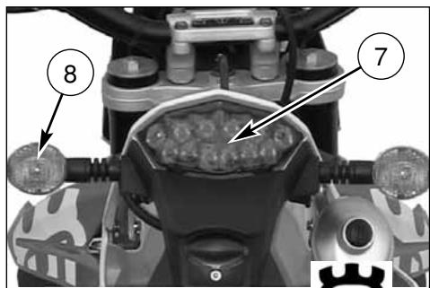
LEGENDE COULEUR CÂBLES (CR)
| Bk-R | Noir - Rouge |
| Bk-W | Noir - Blanc |
| Bk-Y | Noir - Jaune |
| Gr | Gris |
| R | Rouge |
| R-B | Rouge - Blanc |
| W-BI | Blanc - Bleu |
LÉGENDE DU SCHÉMA ÉLECTRIQUE (CR)
U. Eclairage plaque immatriculation
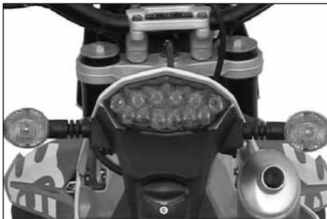
natural_image
Top-down view of a motorcycle's front wheel and dashboard (no visible text or symbols)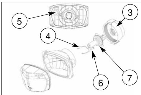
REMPLACEMENT DE L'AMPOULE D'ECLAIRAGE DE LA PLAQUE D'IMMATRICULATION (WR)
natural_image
Close-up of a mechanical component with a numbered annotation (4) pointing to a small feature, no readable text or symbols present.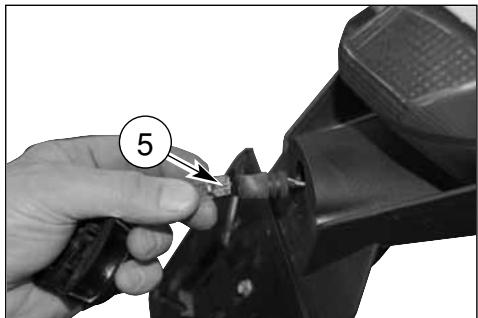
natural_image
Close-up of a hand using a tool to cut a mechanical component, no visible text or symbolsREGLAGE DU PHARE AVANT (WR)
APPENDICE
CONTROLES APRES CHAQUE COMPETITION
natural_image
Close-up of a white and black off-road vehicle's lower body showing tire, suspension, and mechanical components (no visible text or symbols)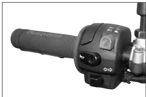
natural_image
Close-up of a black automotive hand crank handle with control knob and adjustment knobs (no visible text or symbols)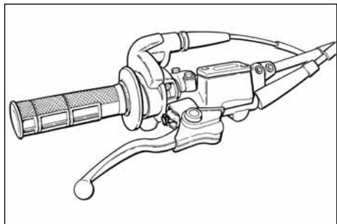
natural_image
Line drawing of a manual brake lever mechanism (no text or symbols)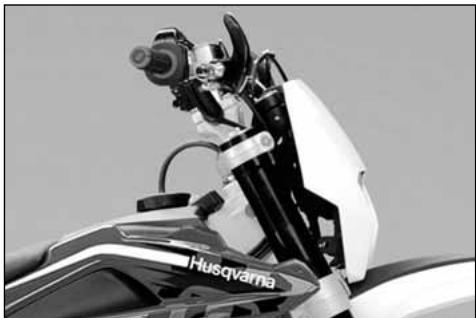
natural_image
Close-up of a motorcycle's front view showing the engine and cockpit (no visible text or symbols)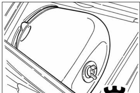
natural_image
Line drawing of a car's front wheel and side door (no text or symbols)natural_image
Close-up of a bicycle's front wheel and brake system with visible springs and hub (no text or symbols)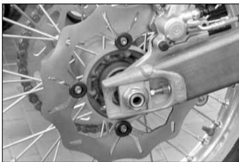
natural_image
Close-up of a bicycle brake system with visible components and wheel rim (no text or symbols)natural_image
Side profile of a white and black off-road motorcycle with visible tracks and wheels (no text or symbols)MOTOCROSS
natural_image
Black-and-white photo of a motorcyclist mid-jump, wearing helmet and gear (no visible text or symbols)ENDURO
natural_image
Side profile of a white and black off-road motorcycle with visible dynamics and wheelbase (no text or symbols)
natural_image
Black-and-white photo of a motorcyclist mid-jump on a dirt track, with mountainous background (no visible text or symbols)WICHTIG
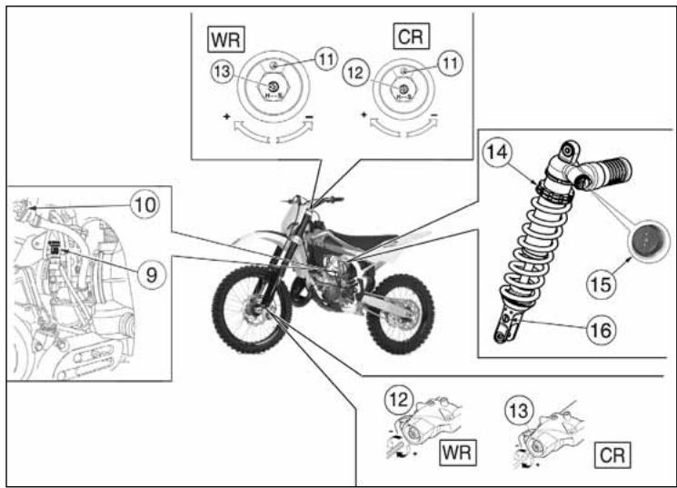
ECHNISCHE DATEN
MOTOR
Anlassen ......kick starter
VENTILSTEUERUNG
Dunlop D756; 80/100x21"
(hinter) (%) 1,0 Kg/cm2
TREIBSTOFF
natural_image
Close-up of a mechanical component with labeled parts (no readable text or symbols)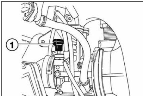
natural_image
Mechanical assembly diagram showing hoses and components (no text or labels)DIGITALINSTRUMENT, KONTROLLLAMPEN (WR)
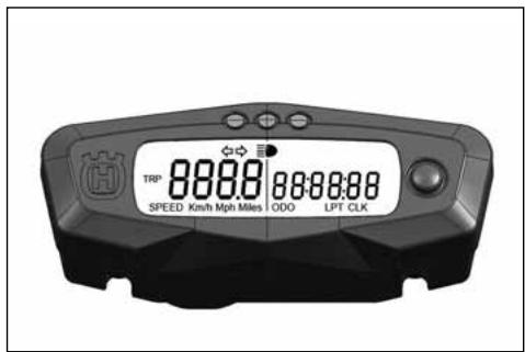
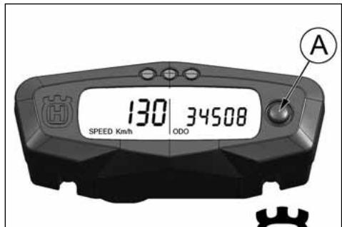
2- SPEED / CLOCK (bild 2)
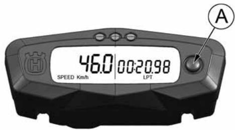
GASANLASSER
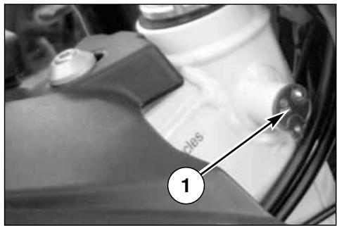
HUMSCHALTER AUF DEM LENKER-LINKE (WR)
DRUCKKNOPF MOTORAN-HALTEN (CR)
natural_image
Technical line drawing of a mechanical component with labeled part (1), no readable text or symbols present.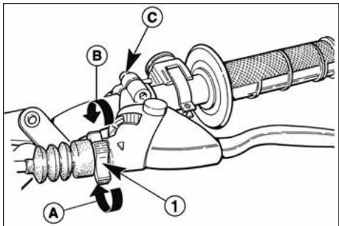
MAN BEACHTE
natural_image
Mechanical assembly diagram showing a motor and linkage mechanism (no text or symbols visible)natural_image
Mechanical assembly diagram showing gear and linkage components (no text or labels)DASS MOTORRAD
VORKONTROLLEN
ACHTUNG!
natural_image
Technical line drawing of a mechanical assembly with no visible text or symbols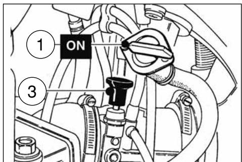
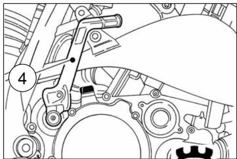
natural_image
Mechanical assembly diagram showing gear and shaft components (no text or labels)MOTORANHALT UND MOTORSTILLSTAND
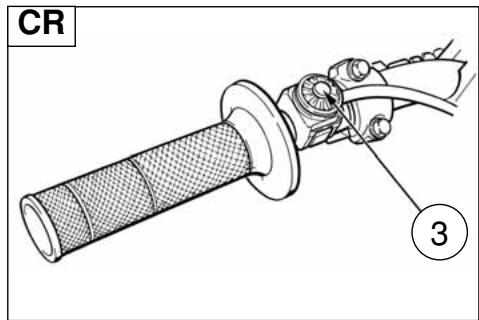
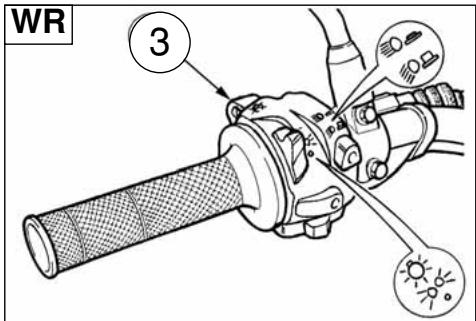
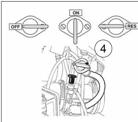
KONTROLLE OLPEGEL WECHSELGETRIEBE
natural_image
Technical line drawing of a mechanical assembly with no visible text or symbols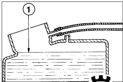
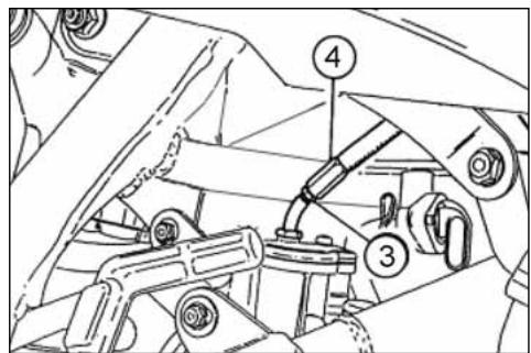
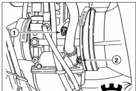
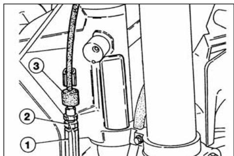
ZÜNDKERZENKONTROLLE
natural_image
Technical line drawing of a spark plug with threaded shaft and threaded end (no text or symbols)2
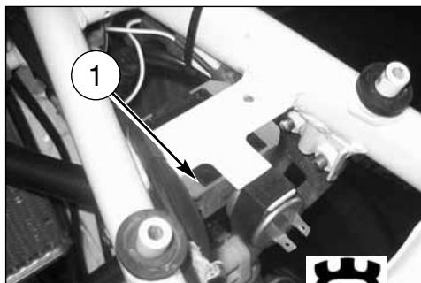
natural_image
Mechanical assembly with numbered component (1) and mechanical parts, no visible text or symbolsKONTROLLE LUFTFILTER
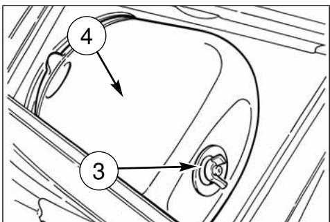
natural_image
Side view of a black-and-white photo of a motorcycle's front wheel and side-mounted disc, showing tire alignment (no text or symbols)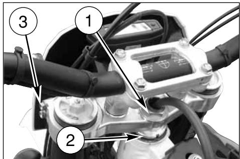
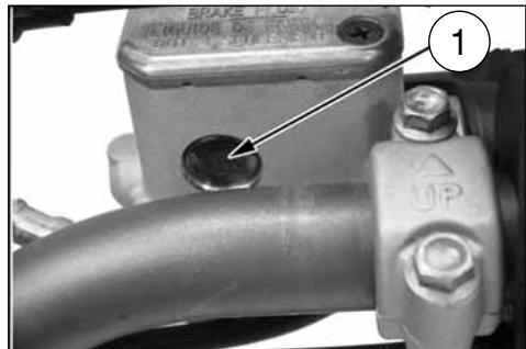
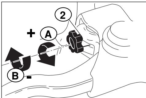
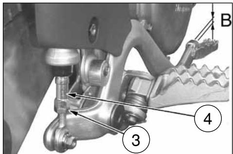
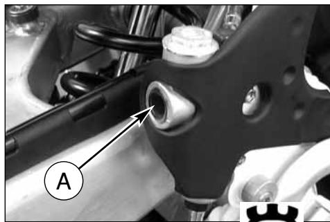
natural_image
Mechanical assembly diagram showing a bracket with labeled component A (no readable text or symbols)natural_image
Black-and-white photo of a motorcyclist riding a dirt bike across a dusty terrain under cloudy skies (no text or symbols visible)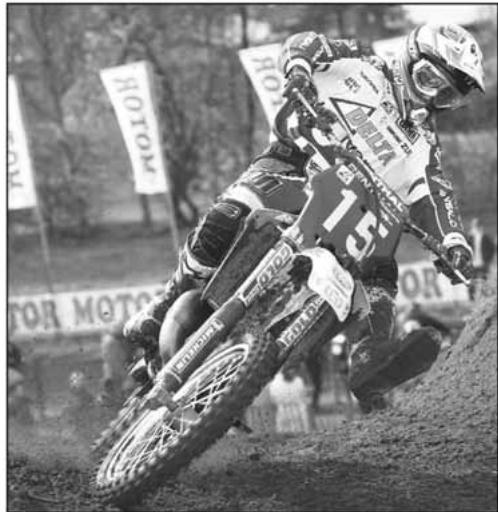
natural_image
Black-and-white photo of a dirter in action on a dirt track, wearing helmet and racing gear, with 'ROTOM' banners visible in background (no readable text on rider or equipment)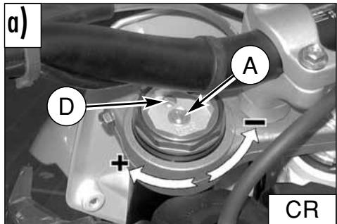
OELSTAND GABEL
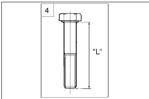
natural_image
Diagram of a mechanical component with a circular part labeled '1' and curved lines, no readable text or symbols present.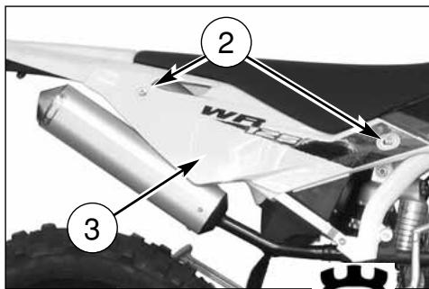
EINSTELLUNG HYDRAULIKBREMSE STOSSDAEMPFER
natural_image
Mechanical assembly diagram showing linkage components with arrows indicating motion (no text or symbols)natural_image
Close-up of a black-and-white photo of a motor with visible wheel, suspension, and gear mechanism (no text or symbols)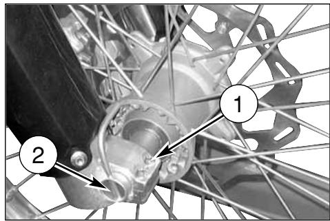
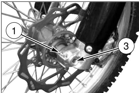
ZUSAMMENBAU DES VORDERRADS
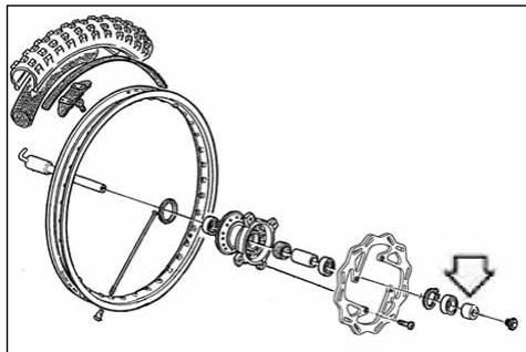
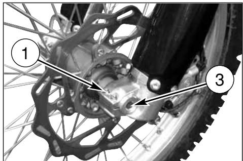
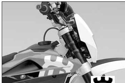
natural_image
Close-up of a motorcycle's front wheel and suspension system (no visible text or symbols)ABNEHMEN DES HINTERRADS
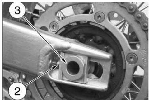
REIFEN
natural_image
Top-down view of a bicycle wheel with visible tire, disc, and hub (no text or symbols)BREMSEN
natural_image
Technical line drawing of a pressure gauge mounted on a stand, surrounded by scaffolding (no text or symbols)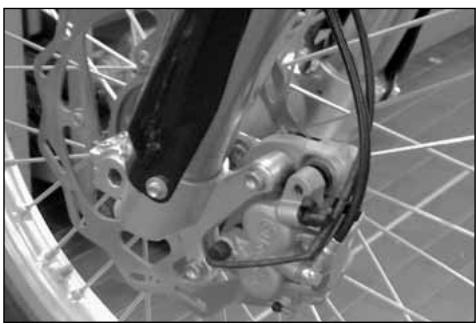
natural_image
Close-up of a bicycle's front wheel and dashboard assembly (no visible text or symbols)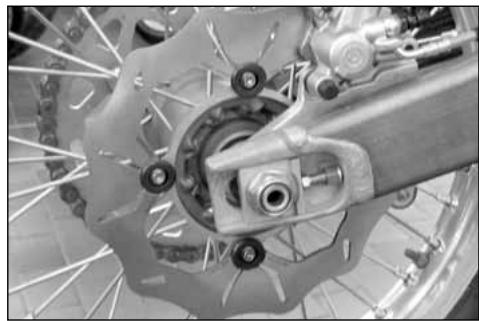
natural_image
Close-up of a bicycle brake system with visible components and suspension rings (no text or symbols)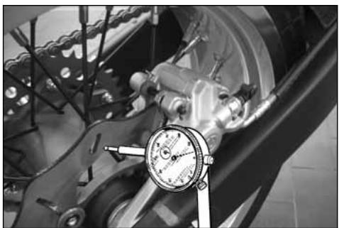
natural_image
Close-up of a mechanical device with a dial indicator (no visible text or symbols)SCHEIBENREINIGUNG
natural_image
Close-up of a bicycle wheel's head and dashboard assembly (no visible text or symbols)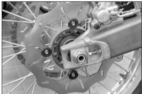
natural_image
Close-up of a bicycle brake system with visible components and wheel rim (no text or symbols)FLUESSIGKEITSWECHSEL
natural_image
Close-up of a bicycle wheel assembly with visible mechanical components and a numbered annotation (1) pointing to a specific part.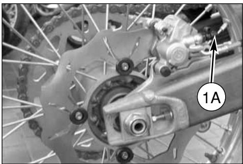
natural_image
Close-up of a bicycle wheel assembly with visible components and a numbered label (1A) pointing to a specific part.ACHTUNG!
natural_image
Side-by-side comparison of bicycle wheel and mechanical components, showing gear assembly and battery connection (no text or symbols visible)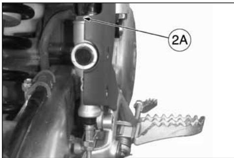
natural_image
Technical line drawing of a mechanical tool with handle and lever (no text or symbols)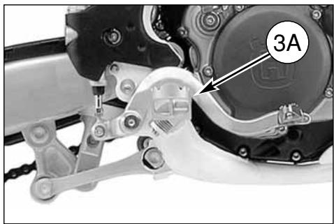
natural_image
Mechanical assembly diagram showing a motor and gear components with labeled part '3A' (no readable text or symbols beyond label)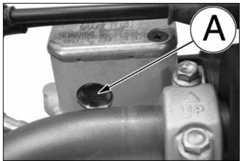
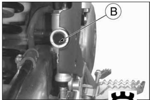
natural_image
Mechanical assembly diagram showing a valve and gear mechanism (no text or symbols)ACHTUNG!
natural_image
Close-up of a bicycle wheel with visible tire, brake caliper, and mechanical components (no text or symbols)natural_image
Close-up of a bicycle wheel assembly with visible mechanical components and a numbered annotation (1) pointing to a specific part.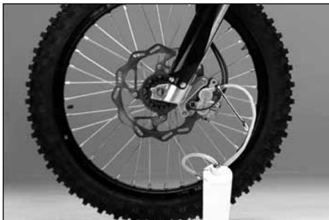
natural_image
Close-up of a bicycle wheel with visible tire, disc brake, and hub assembly (no text or symbols)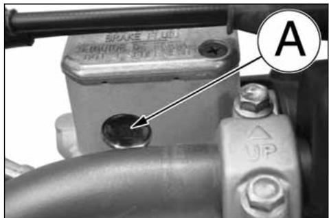

natural_image
Mechanical assembly diagram showing a valve and gear mechanism (no text or symbols)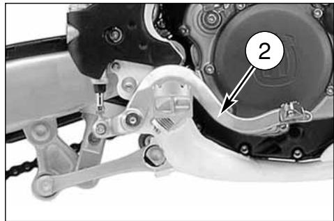
natural_image
Mechanical assembly diagram showing a motor and gear mechanism with labeled component (no readable text or symbols)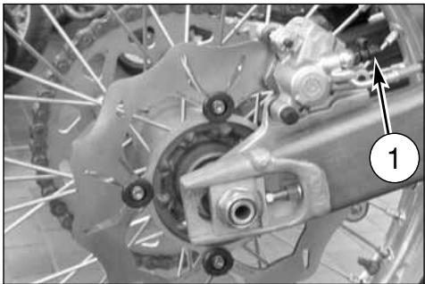
natural_image
Close-up of a bicycle brake system with visible components and a numbered label (1), no readable text or symbols present.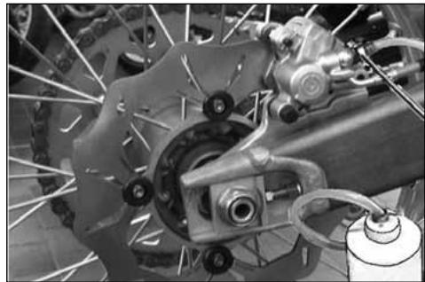
natural_image
Close-up of a bicycle brake system with visible components and suspension links (no text or symbols)ACHTUNG!
natural_image
Mechanical assembly diagram showing a valve and gear components (no text or symbols visible)AUSPUFFDÄMPFER
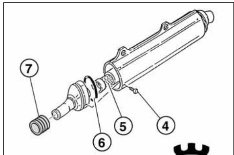
REVISION DES RADS
natural_image
Technical line drawing of a mechanical device with dual gauges and adjustment knobs (no text or symbols)BIEGEN DER RADACHSE
natural_image
Technical line drawing of a pressure gauge mounted on a mechanical component (no text or symbols)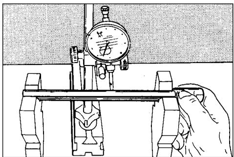
natural_image
Illustration of a hand operating a mechanical testing setup with a dial and clamped components (no text or symbols)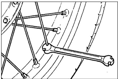
natural_image
Mechanical linkage diagram showing a bone and connecting rods (no text or labels)LAGE DER ELEKTRISCHE KOMPONENTEN
natural_image
Close-up of a mechanical assembly with a circular component and wiring, no visible text or symbols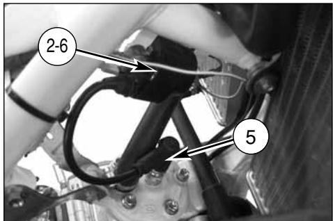
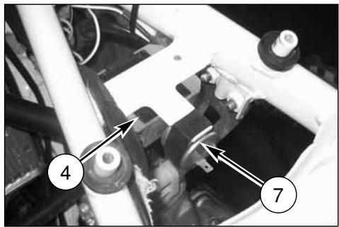
natural_image
Mechanical assembly diagram showing components labeled 4 and 7, with no readable text or symbols beyond labels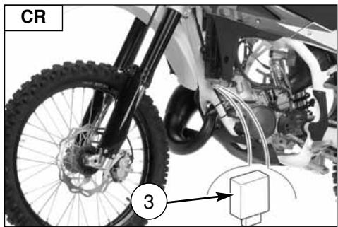
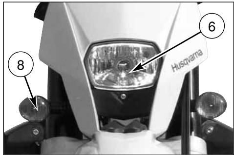
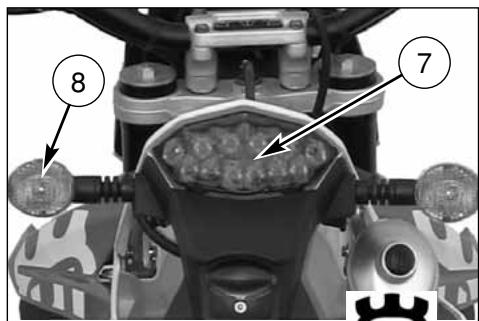
KABELFARBEN (CR)
| Bk-R | Schwarz - Rot |
| Bk-W | Schwarz - Weiss |
| Bk-Y | Schwarz - Gelb |
| Gr | Grau |
| R | Rot |
| R-B | Rot - Weiss |
| W-BI | Weiss - Blau |
KABELFARBEN (WR)
| B | Blau |
| Bk | Schwarz |
| Br | Braun |
| G | Grün |
| Gr | Grau |
| O | Orange |
| Pk | Rosa |
| R | Rot |
| Sb | Hellblau |
| V | Violett |
| W | Weiss |
| Y | Gelb |
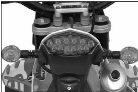
natural_image
Top-down view of a motorcycle's front wheel and dashboard (no visible text or symbols)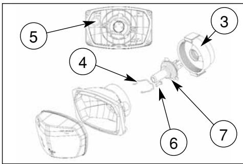
natural_image
Close-up of a mechanical component with a numbered annotation (4) pointing to a small feature, no readable text or symbols present.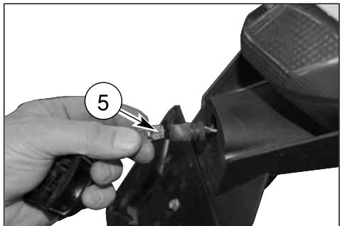
natural_image
Close-up of a hand using a tool to cut a mechanical component, no visible text or symbolsnatural_image
Close-up of a white off-road vehicle's rear suspension system with visible tire tracks and mechanical components (no text or symbols)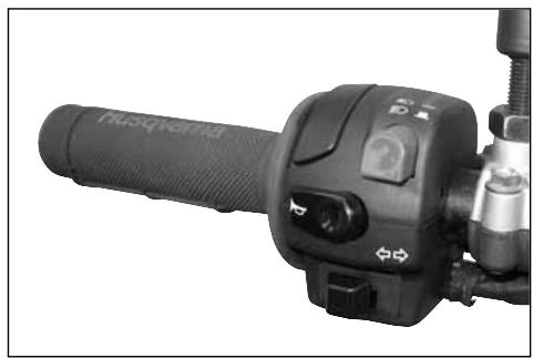
natural_image
Close-up of a black automotive hand crank with control buttons and lever (no visible text or symbols)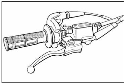
natural_image
Line drawing of a mechanical tool with handle and lever (no text or symbols)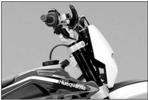
natural_image
Close-up of a motorcycle's front view showing the Husqvarna brand emblem (no text or symbols on the body itself)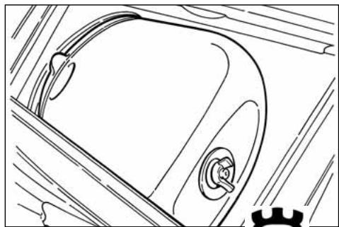
natural_image
Line drawing of a car's front wheel and side door (no text or symbols)natural_image
Close-up of a bicycle's front wheel and brake system with visible springs and hub (no text or symbols)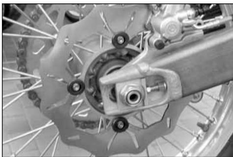
natural_image
Close-up of a bicycle brake system with visible components and wheel rim (no text or symbols)natural_image
Side profile of a white and black off-road motorcycle with visible tracks and wheels (no text or symbols)MOTOCROSS
natural_image
Black-and-white photo of a motorcyclist mid-jump, wearing helmet and gear (no visible text or symbols)ENDURO
natural_image
Side profile of a white and black off-road motorcycle with visible tracks and wheels (no text or symbols)
natural_image
Black-and-white photo of a motorcyclist mid-jump on a dirt track, with mountainous background (no visible text or symbols)IMPORTANTE
INDICE ALFABETICO....62
MANTENIMIENTO PERIODICO/REGULACIONES ......APENDICE A
Notas
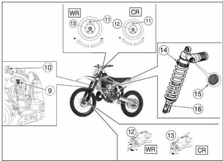
FICHA TECNICA
MOTOR
Válvula del gas (CR)....4,0
Válvula del gas(WR)....5,0
CARBURANTE
natural_image
Close-up of a mechanical component with labeled parts (no readable text or symbols)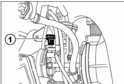
natural_image
Mechanical assembly diagram showing hoses and components (no text or labels)INSTRUMENTO DIGITAL, TESTIGOS (WR)
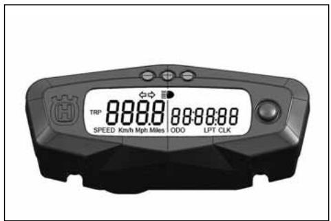
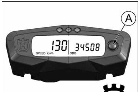
2- SPEED /CLOCK (figura 2)
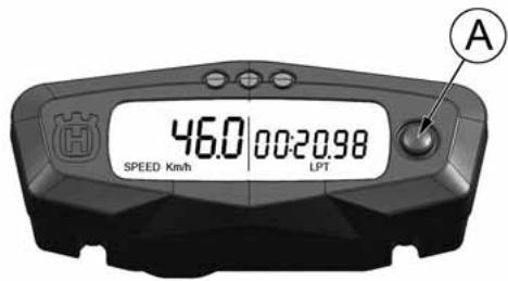
MANDO DEL GAS
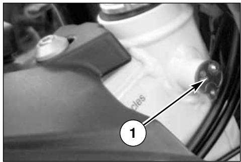
PULSADOR PARADA MOTOR (CR)
natural_image
Technical line drawing of a mechanical clamp or grip assembly (no text or symbols)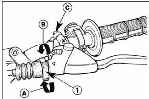
ADVERTENCIA
natural_image
Mechanical assembly diagram showing a motor and gear mechanism with labeled component 1 (no text or symbols beyond label)MANDO DE CAMBIO
natural_image
Mechanical assembly diagram showing gear and components without any text or symbolsINSTRUCCIONES PARA EL USO DE LA MOTOCICLETA
CONTROLES PRELIMINARES
ATENCION!
natural_image
Technical line drawing of a mechanical assembly with no visible text or symbols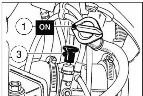
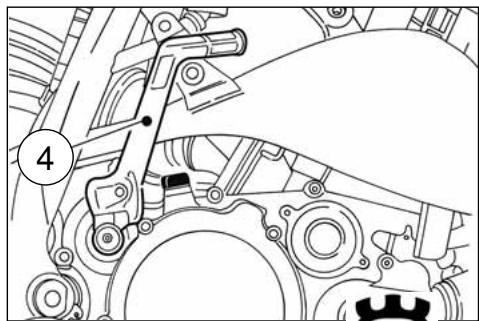
natural_image
Mechanical assembly diagram showing gear and shaft components (no text or labels)PARADA DEL MOTOCICLO Y DEL MOTOR
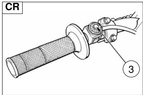
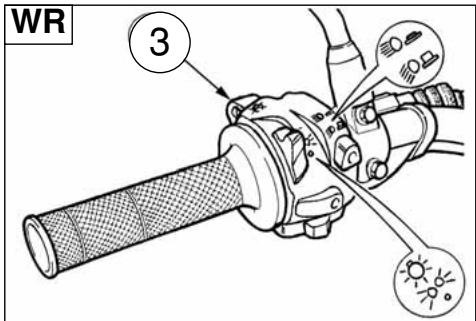
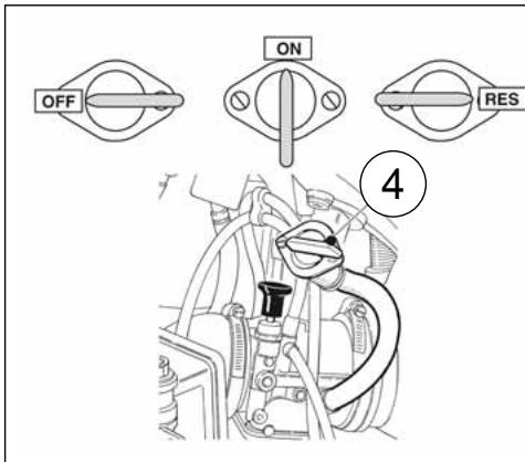
CONTROL NIVEL ACEITE DEL CAMBIO
natural_image
Technical line drawing of a mechanical assembly with no visible text or symbols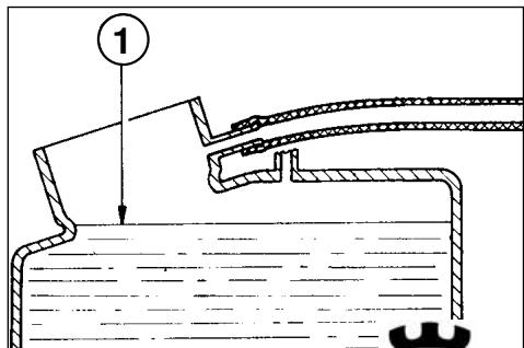
SUBSTITUCION LIQUIDO DE ENFRIAMIENTO
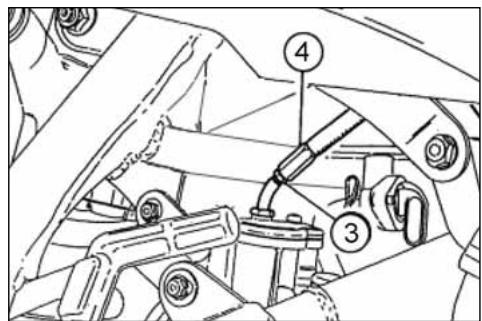
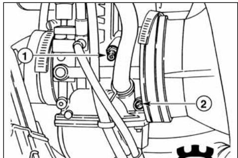
AJUSTE EMBRAGUE
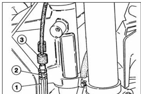
CONTROLLO CANDELA
natural_image
Technical line drawing of a spark plug with threaded end and shaft (no text or symbols)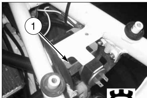
natural_image
Mechanical assembly with numbered component (1) and mechanical parts, no visible text or symbolsCONTROL FILTRO AIRE
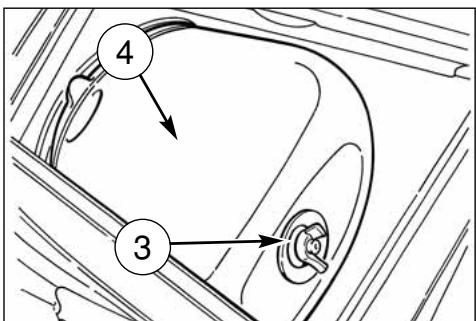
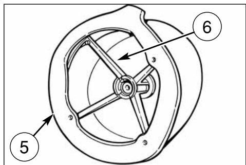
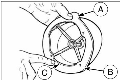
natural_image
Side view of a black-and-white photo of a motorcycle's front wheel and side-mounted disc, showing tire alignment (no text or symbols)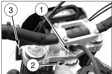
AJUSTE PALANCA DE MANDO FRENO DELANTE- RO Y CONTROL NIVEL FLUIDO
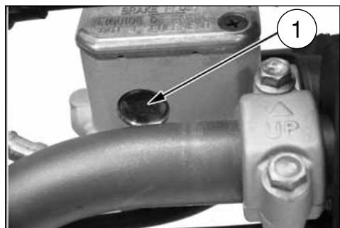
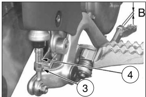
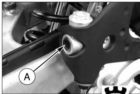
natural_image
Mechanical assembly diagram showing a bracket with labeled component A (no text or symbols beyond label)REGULACION DE LAS SUSPENSIONES SOBRE LA BASE DE PARTICULARES CONDICIONES DE LA PISTA
natural_image
Black-and-white photo of a motorcyclist riding a dirt bike across a dusty terrain under cloudy skies (no text or symbols visible)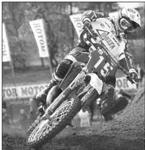
natural_image
Black-and-white photo of a motorcyclist mid-jump, wearing helmet and racing gear, with 'NOTOM' banners in background (no readable text on bike or terrain)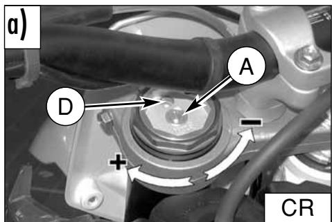
NIVEL DEL ACEITE DE LA HORQUILLA
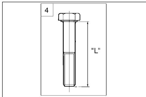
natural_image
Diagram of a mechanical component with a circular part labeled '1' and curved lines, no readable text or symbols present.REGULACION PRECARGA RESORTE AMORTIGUADOR
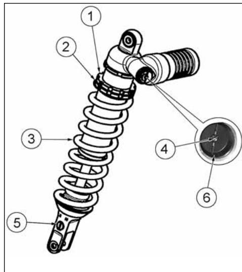
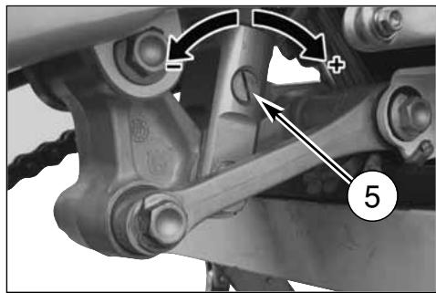
natural_image
Mechanical assembly diagram showing linkage components with arrows and a numbered label (5), no readable text or symbols present.REGULACION CADENA (Fig. A)
natural_image
Close-up of a black-and-white photo of a motor with visible wheel, suspension, and gear mechanism (no text or symbols)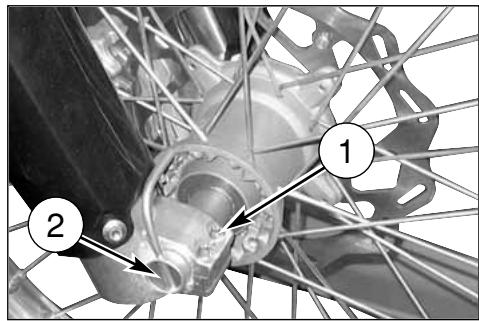
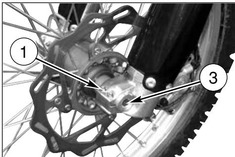
REENSAMBLAJE RUEDA DELANTERA
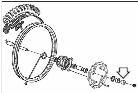
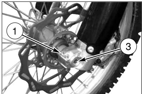
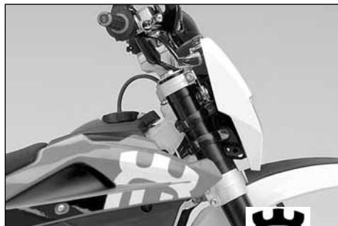
natural_image
Close-up of a motorcycle's front wheel and suspension system (no visible text or symbols)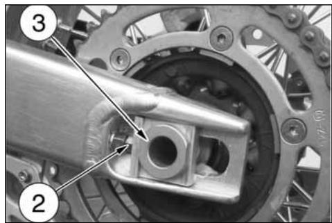
NEUMÁTICOS
natural_image
Top-down view of a bicycle wheel with visible tire, disc, and hub (no text or symbols)FRENOS
natural_image
Technical line drawing of a mechanical gauge or dial mounted on a structural frame (no text or symbols visible)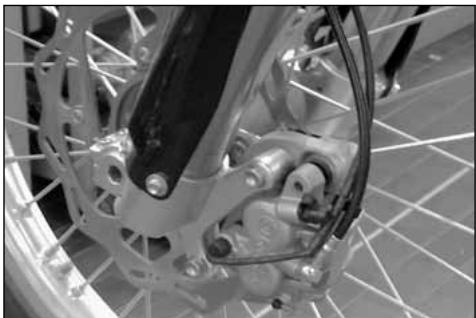
natural_image
Close-up of a bicycle's front wheel and brake system (no visible text or symbols)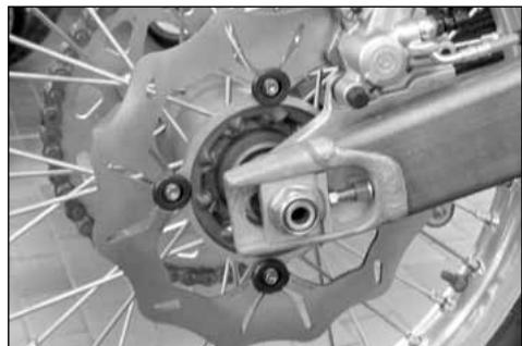
natural_image
Close-up of a bicycle wheel assembly with visible brake calipers and suspension components (no text or symbols)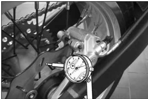
natural_image
Close-up of a mechanical assembly with a dial indicator (no visible text or symbols)LIMPIEZA DEL DISCO
natural_image
Close-up of a bicycle wheel's head and dashboard assembly (no visible text or symbols)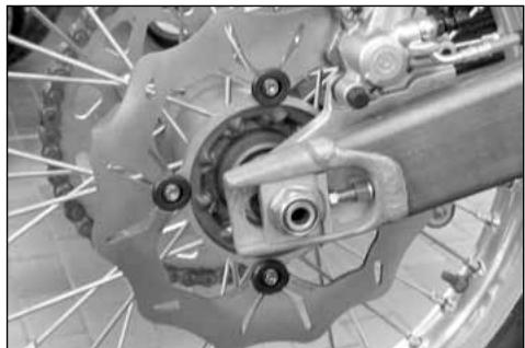
natural_image
Close-up of a bicycle brake system with visible components and wheel rim (no text or symbols)SUBSTITUCION DEL FLUIDO
natural_image
Close-up of a bicycle wheel assembly with visible mechanical components and a numbered annotation (1) pointing to a specific part.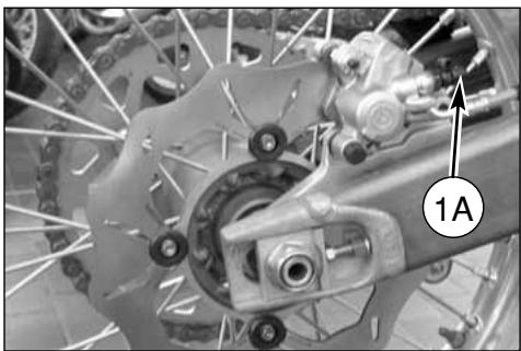
natural_image
Close-up of a bicycle wheel assembly with visible gears and brake calipers (no text or symbols)ATENCION!
natural_image
Side-by-side comparison of a bicycle wheel and its internal mechanical components (no text or symbols visible)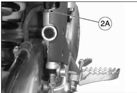
natural_image
Technical line drawing of a mechanical tool with handle and lever (no text or symbols)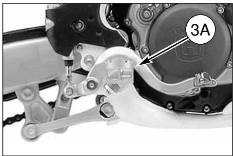
natural_image
Mechanical assembly diagram showing a motor and gear components with labeled part '3A' (no readable text or symbols beyond label)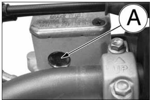
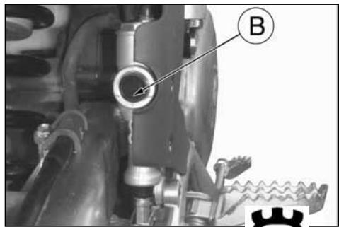
natural_image
Mechanical assembly diagram showing a valve and gear mechanism (no text or symbols)ATENCION!
natural_image
Close-up of a bicycle wheel with visible tire, brake caliper, and mechanical components (no text or symbols)natural_image
Close-up of a bicycle wheel assembly with visible mechanical components and a numbered annotation (1) pointing to a specific part.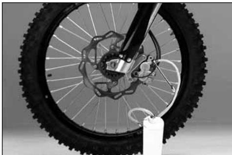
natural_image
Close-up of a bicycle wheel with visible tire, disc brake, and hub assembly (no text or symbols)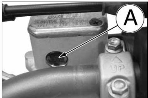
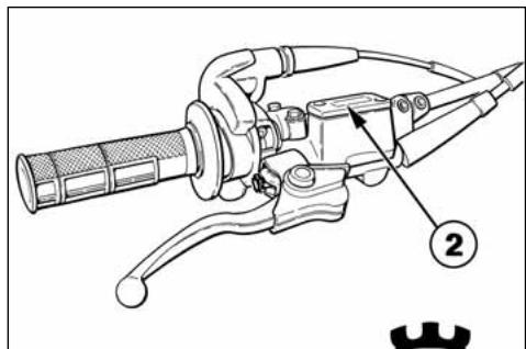
PURGA INSTALACION FRENANTE TRASERA
natural_image
Mechanical component diagram showing a valve assembly with labeled point A (no text or symbols beyond label)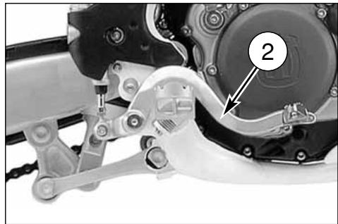
natural_image
Mechanical assembly diagram showing a motor and gear mechanism with labeled component (no readable text or symbols)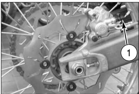
natural_image
Close-up of a bicycle brake system with visible components and a numbered label (1), no readable text or symbols present.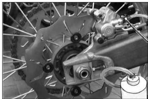
natural_image
Close-up of a bicycle brake system with visible components and suspension rings (no text or symbols)ATENCION!
natural_image
Mechanical assembly diagram showing a valve or fitting with labeled component B (no text or symbols beyond label)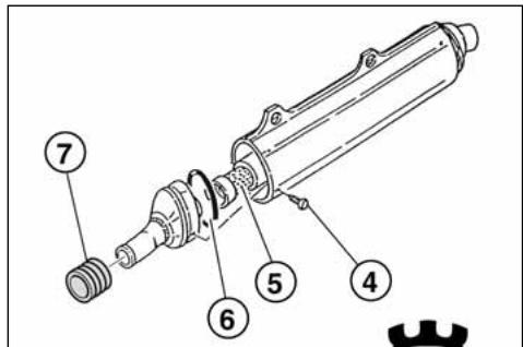
REVISIÓN RUEDAS
natural_image
Technical line drawing of a mechanical device with dual gauges and adjustment knobs (no text or symbols)FLEXIÓN PERNO RUEDA
natural_image
Technical line drawing of a pressure gauge mounted on a mechanical component (no text or symbols)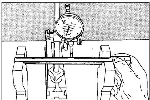
natural_image
Illustration of a hand operating a mechanical testing setup with a dial and clamped components (no text or symbols)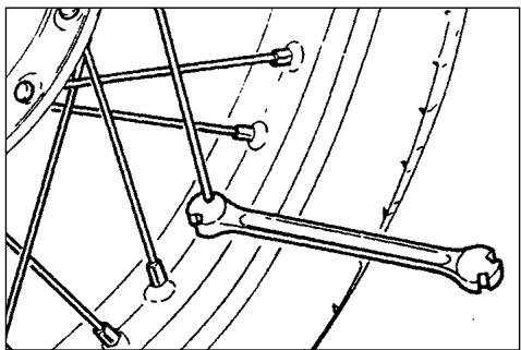
natural_image
Mechanical linkage diagram showing a bone and connecting rods (no text or labels)natural_image
Close-up of a mechanical assembly with a circular component and wiring, no visible text or symbols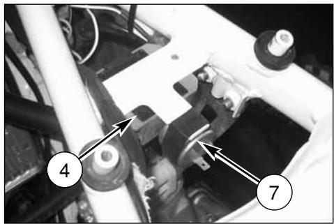
natural_image
Mechanical assembly diagram showing components labeled 4 and 7, with no readable text or symbols beyond labels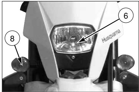
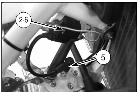
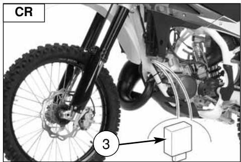
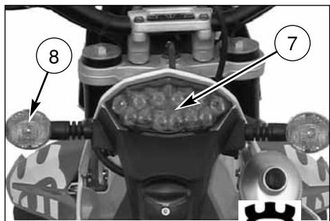
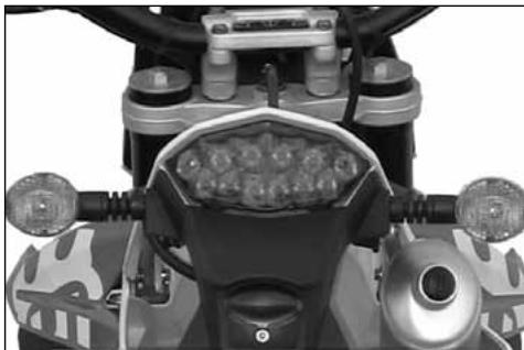
natural_image
Top-down view of a motorcycle's front wheel and dashboard (no visible text or symbols)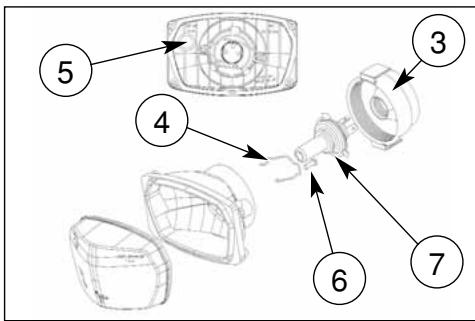
natural_image
Close-up of a mechanical component with a numbered annotation (4) pointing to a small feature, no readable text or symbols present.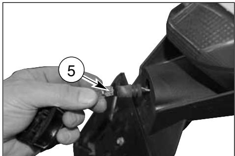
natural_image
Close-up of a hand using a tool to cut a mechanical component, no visible text or symbolsnatural_image
Close-up of a white off-road vehicle's rear suspension system with visible tire tracks and mechanical components (no text or symbols)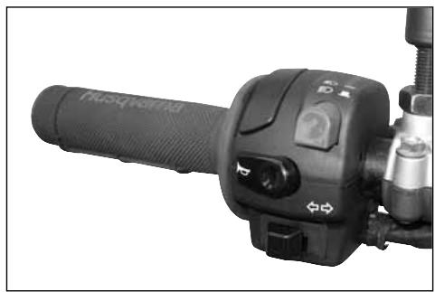
natural_image
Close-up of a black automotive hand crank with control buttons and lever (no visible text or symbols)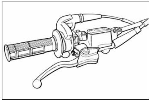
natural_image
Line drawing of a mechanical tool with handle and lever (no text or symbols)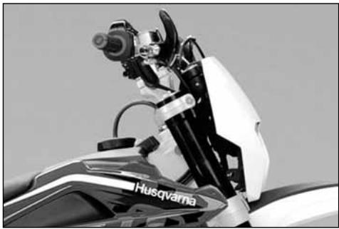
natural_image
Close-up of a motorcycle's front view showing the Husqvarna brand emblem (no text or symbols on the body itself)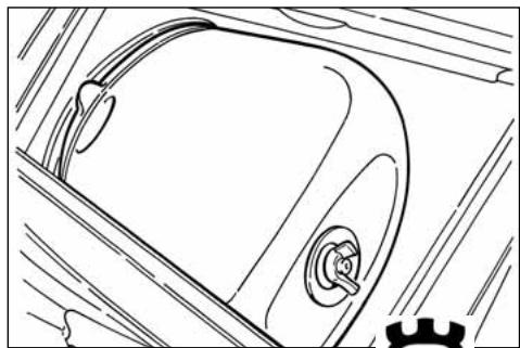
natural_image
Line drawing of a car's front wheel and side door (no text or symbols)natural_image
Close-up of a bicycle's front wheel and brake system with visible springs and hub (no text or symbols)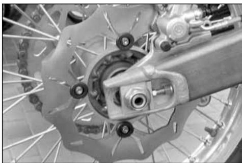
natural_image
Close-up of a bicycle brake system with visible components and wheel rim (no text or symbols)
- IMPORTANTE
- DATI TECNICI
- MOTORE
- CARBURANTE
- STRUMENTO DIGITALE, SPIE (WR)
- 2- SPEED / CLOCK (figura 2)
- COMANDO GAS
- COMMUTATORE SINISTRO SUL MANUBRIO (WR)
- PULSANTE ARRESTO MOTORE (CR)
- AVVERTENZA
- COMANDO CAMBIO
- ISTRUZIONI PER L'USO DEL MOTOCICLO
- CONTROLLI PRELIMINARI
- ATTENZIONE!
- ARRESTO DEL MOTOCICLO E DEL MOTORE
- CONTROLLO CANDELA
- CONTROLLO FILTRO ARIA
- REGOLAZIONE LEVA COMANDO E CONTROLLO LIVELLO FLUIDO FRENO ANTERIORE
- LIVELLO OLIO FORCELLA
- REGISTRAZIONE AMMORTIZZATORE
- REGISTRAZIONE CATENA (Fig. A)
- CONTROLLO USURA CATENA, PIGNONE, CORONA
- RIMONTAGGIO RUOTA ANTERIORE
- SMONTAGGIO RUOTA POSTERIORE
- PNEUMATICI
- FRENI
- PULIZIA DISCO
- SOSTITUZIONE FLUIDO
- AVVERTENZA!
- SPURGO IMPIANTO FRENANTE ANTERIORE
- SPURGO IMPIANTO FRENANTE POSTERIORE
- SILENZIATORE DI SCARICO
- REVISIONE RUOTE
- PIEGATURA PERNO RUOTA
- SOSTITUZIONE LAMPADA LUCE TARGA (WR)
- REGISTRAZIONE FANALE ANTERIORE (WR)
- IMPORTANT NOTICES
- IMPORTANT
- Important Notice
- Parts Replacement
- PRECAUTIONS FOR CHILDREN WARNING
- TABLE OF CONTENTS Page
- Note
- IDENTIFICATION DATA
- CONTROL LOCATION
- TECHNICAL DATA
- ENGINE
- TIMING SYSTEM
- LUBRICATION
- IGNITION
- FUEL SYSTEM
- PRIMARY DRIVE
- CLUTCH
- TRANSMISSION
- SECONDARY DRIVE
- FINAL RATIOS
- FRAME
- FRONT SUSPENSION
- REAR SUSPENSION
- FRONT BRAKE
- REAR BRAKE
- TYRES
- Cold tire pressure
- DIMENSION, WEIGHT, CAPACITY
- CONTROLS
- FUEL COCK
- WARNING\*: Be careful not to touch the hot engine while operating the fuel valve.
- SIDESTAND
- CARBURETOR CHOKE
- DIGITAL INSTRUMENT, WARNING LIGHTS (WR)
- NOTES
- 2- SPEED / CLOCK (figure 2)
- 3- SPEED / TRIP 1 (figure 3)
- 4- SPEED / CHRONO (STP) (figure 4)
- THROTTLE CONTROL
- CAUTION
- FRONT BRAKE CONTROL
- STEERING LOCK (WR)
- HANDLEBAR COMMUTATOR (WR)
- ENGINE STOP BUTTON (CR, WR USA-CDN)
- CLUTCH CONTROL
- REAR BRAKE CONTROL
- GEAR SHIFT CONTROL
- KICKSTART PEDAL
- RIDING
- Check all fluids
- WARNING\*: Don't remove radiator cap when hot!
- Check all controls
- Check brakes
- Check suspensions
- Check wheels
- Check chain rollers and sprockets
- Check air filter and intake system
- Check exhaust system
- Check torque
- Check steering action
- Check the electric system (WR).
- WARNING\*: Failure to perform these checks every day before you ride may result in serous damage or a severe accident.
- RUNNING IN
- CHECKS WHILE RUNNING IN
- ENGINE START
- IMPORTANT NOTE IN CASE OF COLD STARTS AT LOW TEMPERATURES
- STOPPING THE MOTORCYCLE AND THE ENGINE
- TRANSMISSION OIL LEVEL CHECKING
- Transmission oil level
- TRANSMISSION OIL CHANGE
- Note:
- COOLANT LEVEL CHECK
- WARNING
- REPLACEMENT OF COOLING FLUID
- WARNING\*: Coolant on tires will make them slippery and can cause an accident or injury.
- THROTTLE CABLE ADJUSTMENT
- IDLING ADJUSTMENT
- CLUTCH ADJUSTMENT
- VOLTAGE REGULATOR (WR)
- AIR FILTER CHECK
- AIR FILTER AND CLEANING
- ASSEMBLY
- STEERING WHEEL BALL PLAY ADJUSTMENT
- REAR BRAKE PEDAL POSITION ADJUSTMENT
- REAR BRAKE IDLE STROKE ADJUSTMENT
- CHECKING THE FLUID LEVEL
- ADJUSTING THE SUSPENSIONS ACCORDING TO PARTICULAR TRACK CONDITIONS
- HARD GROUND
- SANDY GROUND
- MUDDY GROUND
- ADJUSTING THE COMPRESSION FORK
- OIL FORK LEVEL
- HANDLEBAR POSITION AND HEIGHT CHANGE
- ADJUSTING THE SHOCK ABSORBER SPRING PRELOAD
- SHOCK ABSORBER DAMPING ADJUSTMENT
- CHAIN ADJUSTMENT (Fig. A)
- Fast adjustment (Fig. B.)
- CHECKING THE WEAR OF CHAIN, PINION AND SPROCKET
- LUBRICATING THE CHAIN
- Disassembling and cleaning
- Washing the chain without OR (\*)
- Washing the chain with OR ( · )
- Lubricating the chain without OR (\*)
- Lubricating the chain with OR ( · )
- Chain tension rollers, chain driving roller, chain guide, chain runner
- REMOVING THE FRONT WHEEL
- REASSEMBLING THE FRONT WHEEL
- REMOVING THE REAR WHEEL
- TIRES
- MINIMUM HEIGHT OF THE TREAD
- BRAKES
- LEGEND
- BRAKE PADS REMOVAL
- CAUTION!
- PADS WEAR
- PADS CLEANING
- PADS INSTALLATION
- WARNING!
- BRAKE DISC WEAR
- DISC WARPAGE
- DISC CLEANING
- FLUID CHANGE
- To replace the fluid, proceed as follows:
- REAR BRAKING SYSTEM BLEEDING
- EXHAUST MUFFLER
- REPLACING MUFFLER DEADENING MATERIAL
- OVERHAULING THE WHEELS
- WHEEL SPOKES
- WHEEL RIM AXLE BENDING
- ELECTRICAL COMPONENTS LOCATION
- KEY TO ELECTRIC DIAGRAM (CR)
- KEY TO ELECTRIC DIAGRAM (WR)
- HEADLAMP BULBS REPLACEMENT (WR)
- TAIL LIGHT (WR)
- REPLACING THE NUMBER PLATE LAMP (WR)
- ADJUSTMENT OF HEADLIGHT (WR)
- EQUIPMENT
- APPENDIX
- AFTER-RACE CHECK POINTS
- STORAGE
- Never litter the environment with fuel, and let the engine running in open air, never in closed rooms.
- CLEANING
- IMPORTANT RECOMMENDATION
- NOTES FOR USA/CDN MODEL
- DISCLAIMER OF WARRANTY
- Noise emission warranty
- SPARK ARRESTER
- "SPARK ARRESTER" MAINTENANCE AND CLEANOUT INSTRUCTIONS
- ALPHABETIC INDEX
- A
- B
- C
- D
- E
- F
- G
- H
- |
- L
- M
- 0
- P
- R
- S
- T
- V
- W
- FRANÇAIS
- Husqvarna
- PRESENTATION
- DONNEES TECHNIQUES
- MOTEUR
- DIMENSIONS, POIDS, CAPACITE
- CARBURANT
- INSTRUMENT DIGITAL, VOYANTS (WR)
- POIGNEE DES GAZ
- COMMUTATEUR GAUCHE SUR LE GUIDON (WR)
- BOUTON D'ARRET MOTEUR (CR)
- ATTENTION
- COMMANDE DU CHANGEMENT DE VITESSES
- MODE D'EMPLOI DE LA MOTO
- CONTROLES PRELIMINAIRES
- ATTENTION!
- ARRET DU MOTOCYCLE ET DU MOTEUR
- CONTROLE DU NIVEAU D'HUILE DU BOITE DE VITESSE
- SUBSTITUTION DU LIQUIDE DE REFROIDISSEMENT
- REGLAGE DE L'EMBRAYAGE
- CONTROLE DE LA BOUGIE D'ALLUMAGE
- CONTROLE FILTRE A AIR
- NETTOYAGE FILTRE A AIR
- REGLAGE DU LEVIER DU FREIN AVANT ET CONTRÔLE DU NIVEAU FLUIDE FREIN AVANT
- REGLAGE POSITION PEDALE FREIN ARRIERE
- REGLAGE DES SUSPENSION PAR RAPPORT AUX CONDITIONS DE LA PISTE
- NIVEAU D'HUILE DE LA FOURCHE
- CONTROLE USURE CHAINE, PIGNON ET COURONNE
- RÉMONTAGE DE LA ROUE AVANT
- DÉMONTAGE DE LA ROUE ARRIÈRE
- PNEUS
- FREIN
- NETTOYAGE DU DISQUE
- REPLACEMENT DU FLUIDE
- CURAGE INSTALLATION DE FREINAGE AVANT
- CURAGE DU SYSTEME DE FREINAGE ARRIERE
- SILENCIEUX D'ECHAPPEMENT
- REVISION DES ROUES
- COURBURE PIVOT ROUE
- POSITION COMPOSANTS ÉLECTRIQUES
- LÉGENDE DU SCHÉMA ÉLECTRIQUE (CR)
- REMPLACEMENT DE L'AMPOULE D'ECLAIRAGE DE LA PLAQUE D'IMMATRICULATION (WR)
- REGLAGE DU PHARE AVANT (WR)
- APPENDICE
- CONTROLES APRES CHAQUE COMPETITION
- WICHTIG
- ECHNISCHE DATEN
- MOTOR
- VENTILSTEUERUNG
- TREIBSTOFF
- DIGITALINSTRUMENT, KONTROLLLAMPEN (WR)
- 2- SPEED / CLOCK (bild 2)
- GASANLASSER
- HUMSCHALTER AUF DEM LENKER-LINKE (WR)
- DRUCKKNOPF MOTORAN-HALTEN (CR)
- MAN BEACHTE
- DASS MOTORRAD
- VORKONTROLLEN
- MOTORANHALT UND MOTORSTILLSTAND
- KONTROLLE OLPEGEL WECHSELGETRIEBE
- ZÜNDKERZENKONTROLLE
- KONTROLLE LUFTFILTER
- OELSTAND GABEL
- EINSTELLUNG HYDRAULIKBREMSE STOSSDAEMPFER
- ZUSAMMENBAU DES VORDERRADS
- ABNEHMEN DES HINTERRADS
- REIFEN
- BREMSEN
- SCHEIBENREINIGUNG
- FLUESSIGKEITSWECHSEL
- ACHTUNG!
- AUSPUFFDÄMPFER
- REVISION DES RADS
- BIEGEN DER RADACHSE
- LAGE DER ELEKTRISCHE KOMPONENTEN
- Notas
- FICHA TECNICA
- INSTRUMENTO DIGITAL, TESTIGOS (WR)
- 2- SPEED /CLOCK (figura 2)
- MANDO DEL GAS
- PULSADOR PARADA MOTOR (CR)
- ADVERTENCIA
- MANDO DE CAMBIO
- INSTRUCCIONES PARA EL USO DE LA MOTOCICLETA
- CONTROLES PRELIMINARES
- PARADA DEL MOTOCICLO Y DEL MOTOR
- CONTROL NIVEL ACEITE DEL CAMBIO
- SUBSTITUCION LIQUIDO DE ENFRIAMIENTO
- AJUSTE EMBRAGUE
- CONTROL FILTRO AIRE
- AJUSTE PALANCA DE MANDO FRENO DELANTE- RO Y CONTROL NIVEL FLUIDO
- REGULACION DE LAS SUSPENSIONES SOBRE LA BASE DE PARTICULARES CONDICIONES DE LA PISTA
- NIVEL DEL ACEITE DE LA HORQUILLA
- REGULACION PRECARGA RESORTE AMORTIGUADOR
- REGULACION CADENA (Fig. A)
- REENSAMBLAJE RUEDA DELANTERA
- NEUMÁTICOS
- FRENOS
- LIMPIEZA DEL DISCO
- SUBSTITUCION DEL FLUIDO
- ATENCION!
- PURGA INSTALACION FRENANTE TRASERA
- REVISIÓN RUEDAS
- FLEXIÓN PERNO RUEDA
Brand : HUSQVARNA
Model : CR 125
Category : Motorcycle