417-060 - Air conditioner Anslut - Free user manual and instructions
Find the device manual for free 417-060 Anslut in PDF.


| Product Type | Portable Air Conditioner |
| Brand | Anslut |
| Model | 417-060 |
| Dimensions (WxHxD) | 350 x 750 x 380 mm |
| Weight | 24.5 kg |
| Power Supply | 230 VAC |
| Cooling Power | 2100 W |
| Cooling Capacity | 6380 BTU/h |
| EER | 2.7 |
| Energy Class | A |
| Dehumidifying Capacity | 19 l/24 hours |
| Airflow | 370 m³/h |
| Noise Level | 65 dB |
| Refrigerant | R410A (360 g) |
| Temperature Range (Cooling) | 17–35 °C |
| Cord Length | 1.8 m |
| Operating Modes | Auto, Cool, Dry, Fan (Heat on some models) |
| Remote Control | Yes (with LCD display) |
| Timer | 24-hour programmable ON/OFF |
| Sleep/Economy Mode | Yes |
| Air Filter | Washable (clean every 2 weeks) |
| Auto Restart | Yes (after power failure) |
| Safety Features | Overheat protection, 3-minute restart delay |
| Window Installation Kit | Included (for sash windows) |
| Warranty | Refer to manufacturer |
Frequently Asked Questions - 417-060 Anslut
User questions about 417-060 Anslut
0 question about this device. Answer the ones you know or ask your own.
Ask a new question about this device
Download the instructions for your Air conditioner in PDF format for free! Find your manual 417-060 - Anslut and take your electronic device back in hand. On this page are published all the documents necessary for the use of your device. 417-060 by Anslut.
USER MANUAL 417-060 Anslut
natural_image
White portable air conditioner with ventilation slots and a remote control unit (no visible text or symbols)SE Bruksanvisning för luftkonditionering
NO Bruksanvisning for klimaanlegg
PL Instrukcja obsługi klimatyzatora
EN User Instructions for Air Conditioner
SE - Bruksanvisning i original
NO - Bruksanvisning i original
EN - Operating instructions in original
Date of production: 2014-07-10
© Jula AB
SVENSKA....7
SÄKERHETSANVISNINGAR....7
Energispartips....8
TEKNISKA DATA....8
BESKRIVNING 9
DELAR....9
DRIFTFÖRHÅLLAnDEN....9
TILLBEHÖR 10
VERKTYG FÖR MONTERING AV FÖNSTERINSATS 10
ANVÄNDNING....11
MANÖVERPANEL OCH DISPLAY.... 11
FELKODER....12
ENERGISPARLÄGE 12
ANVÄNDNING 13
Övrigt 14
FJÄRRKONTROLLEN 15
MONTERING....27
PLACERING 27
MONTERING AV FÖNSTERINSATS 27
MONTERING I SKJUTFÖNSTER SOM ÖPPNAS VERTIKALT (TILLVAL) 28
MONTERING I SKJUTFÖNSTER SOM ÖPPNAS HORIZONTELLT (TILLVAL) 29
MONTERING AV UTLOPPSSLANG....30
MONTERING AV DRÄNERING. 31
UNDERHÅLL OCH SKÖTSEL ....32
Luftfilter 32
Hölje....32
STR∅MSPAREMODUS....39
BRUK....40
Annet 41
FJERNKONTROLLEN 42
MONTERING 54
PLASSERING 54
MONTERING AV VINDUSINNSATS 54
MONTERING I SKYVEVINDU SOM ÅPNES VERTIKALT (TILLEGGSUTSTYR)....55
MONTERING I SKYVEVINDU SOM ÅPNES HORIZONTALT (TILLEGGSUTSTYR)....56
MONTERING AV UTL∅PSSLANGE....57
MONTERING AV DRENERING....58
VEDLIKEHOLD OG RENGJ∅RING 59
Luftfilter 59
Deksel....59
MONTAŻ W OKNIE PRZESUWANYM OTWIERANYM PIONOWO (OPCJA DODATKOWA) .....82
MONTAŻ W OKNIE PRZESUWANYM OTWIERANYM POZIOMO (OPCJA DODATKOWA)....83
MONTAŻ WEŻA ODPROWADZAJĄCEGO....84
MONTAŻ DRENAŻU....85
KONSERWACJA I PIELEGNACJA 86
SAFETY INSTRUCTIONS 88
Energy saving tips....89
TECHNICAL DATA 89
DESCRIPTION 90
PARTS 90
OPERATING CONDITIONS 90
ACCESSORIES 91
TOOLS FOR MOUNTING WINDOW INSERT 91
USE 92
CONTROL PANEL AND DISPLAY 92
ERROR CODES....93
ENERGY SAVER MODE....93
USE....94
Miscellaneous....95
REMOTE CONTROL 96
INSTALLATION....108
POSITIONING 108
FITTING THE WINDOW INSERT 108
INSTALLATION IN SASH WINDOW THAT OPENS VERTICALLY (OPTION) .....109
INSTALLATION IN SASH WINDOW THAT OPENS HORIZONTALLY (OPTION) 110
INSTALLATION OF OUTLET HOSE....111
INSTALLATION OF DRAIN....112
CARE AND MAINTENANCE....113
Air filter....113
Casing....113
If the appliance is not going to be used for some time. 113
SÄKERHETSANVISNINGAR
natural_image
Line drawing of a portable electronic device with a grid-patterned arm and control panel (no text or symbols)ENERGISpARTIpS

Fig. 2 Fig. 1
Framsida (fig 1)
Grader Celsius (°C): RG51B14/(C)E, RG51B16/(C)E, RG51B18/(C)E, RG51B31/(C)E, RG51B19/(C)E-M, RG51B20/(C)E, RG51 B25/(C)E, RG51 B27/(C)E, RG51 B30/(C)E.
Grader Fahrenheit (°F): RG51B/(C)EU, RG51B1/(C)EU, RG51B17/(C)EU, RG51B26/(C)EU, RG51B30/(C)EU, RG51B32/(C)EU, RG51B31/(C)EU.
FUNKTIONER
Modell RG51B14/(C)E, RG51B16/(C)E, RG51B18/(C)E, RG51B19/(C)E-M, RG51B20/(C)E, RG51B31/(C)E, RG51B30/(C)E.
OBS!
- Modell RG51B16/(C)E, RG51B18/(C)E saknar funktionen SWING.
- Modell RG51B18/(C)E, RG51B19/(C)E-M, RG51B20/(C)E saknar knappen LED DISPLAY.
- Modell RG51B19/(C)E-M saknar funktionen MED FAN.
- Modell RG51B31/(C)E har knapp ECONO-MY i stället för knapp SLEEP.
- Modell RG51B30/(C)E saknar funktionerna MED FAN och SWING.
1. TEMp DOWN
natural_image
Diagram of a portable air conditioner unit with cooling fins and ventilation slots (no text or labels)eller
natural_image
Line drawing of a portable air conditioner unit with cooling fins and a shelf (no text or symbols)Fig. 6

natural_image
Diagram of a portable air conditioner unit with airflow direction arrows (no text or symbols)
natural_image
Diagram of a portable air conditioner unit with airflow arrows (no text or symbols)Fig. 7
pLACERING
natural_image
Two cylindrical pipe fittings with curved arrows indicating rotation or movement (no text or symbols)Fig. 16 Fig. 17

natural_image
Line drawing of a portable air conditioner unit with side-mounted cylindrical housing (no text or symbols)Fig. 18

Fig. 19
natural_image
Diagram showing a vehicle and a curved road with diagonal lines, no text or symbols presentFig. 20
natural_image
Line drawing of a device with a grid array and handle (no text or symbols)STR∅MSpARETIpS

Fig. 2 Fig. 1
Forside (fig. 1)
- Betjeningspanel
- Betjeningsspak for luftretter (manuell innstilling)
- Bærehåndtak (på begge sidene)
- Mottaker for fjernkontrollsignal
- Panel
Bakside (fig. 2)
Fig. 4
Fjernkontrollen har to batterier (R03) under et deksel på baksiden.
Grader celsius (°C): RG51B14/(C)E, RG51B16/(C)E, RG51B18/(C)E, RG51B31/(C)E, RG51B19/(C)E-M, RG51B20/(C)E, RG51 B25/(C)E, RG51 B27/(C)E, RG51 B30/(C)E.
Grader fahrenheit (°F): RG51B/(C)EU, RG51B1/(C)EU, RG51B17/(C)EU, RG51B26/(C)EU, RG51B30/(C)EU, RG51B32/(C)EU, RG51B31/(C)EU.
FUNKSJONER
Modell RG51B14/(C)E, RG51B16/(C)E, RG51B18/(C)E, RG51B19/(C)E-M, RG51B20/(C)E, RG51B31/(C)E, RG51B30/(C)E.
OBS!
EKSEMPEL PÅ TIDSURINNSTILLING
6.0 h
TIMER ON

natural_image
Diagram of a portable air conditioner unit with cooling fan and ventilation slots (no text or labels)eller
Vindusinnsats Min. 67,5 cm Maks. 123 cm

natural_image
Line drawing of a portable air conditioner unit with cooling fins and a hanging rack (no text or symbols)Fig. 6

Vindusinnsats Min. 67,5 cm Maks. 123 cm

natural_image
Diagram of a portable air conditioner unit with airflow direction arrows (no text or symbols)
Vindusinnsats Min. 67,5 cm Maks. 123 cm
natural_image
Line drawing of a portable air conditioner unit with airflow direction arrows (no text or symbols)Fig. 7
pLASSERING
natural_image
Technical line drawing of two identical mechanical components with a central hole, labeled 'eller' (no text or symbols on the components themselves)Fig. 14
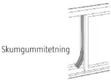
Fig. 15
natural_image
Two cylindrical pipe fittings with curved arrows indicating rotation or movement (no text or symbols)Fig. 16 Fig. 17

natural_image
Line drawing of a portable air conditioner unit with side-mounted cylindrical housing (no text or symbols)Fig. 18

natural_image
Diagram showing a vehicle and a curved road with diagonal lines crossing (no text or symbols)Fig. 20
natural_image
Simple line drawing of a trash bin with no text or symbolsVerne om miljøet!
natural_image
Line drawing of a portable air conditioner unit with a grid-patterned arm (no text or symbols)
Rys. 2Rys. 1
przód (rys. 1)
Model RG51B14/(C)E, RG51B16/(C)E, RG51B18/(C)E, RG51B19/(C)E-M, RG51B20/(C)E, RG51B31/(C)E, RG51B30/(C)E.
UWAGA!
natural_image
Diagram of a device with a cooling tower and directional arrows indicating airflow or movement (no text or symbols present)lub
natural_image
Line drawing of a portable air conditioner unit with cooling fins and a hanging rack (no text or symbols)Rys. 6
natural_image
Diagram of a portable air conditioner unit with airflow direction arrows (no text or symbols)
natural_image
Diagram of an air conditioner unit with airflow arrows indicating direction (no text or symbols)Rys. 7
LOKALIZACJA
natural_image
Line drawing of a portable air conditioner unit with a side-view internal structure (no text or symbols)Rys. 18
natural_image
Diagram showing a vehicle and a curved road with diagonal lines, no text or symbols presentRys. 20
Read the User Instructions carefully before use.
Save these instructions for future reference.
Always follow basic safety precautions to reduce the risk of personal injury and/or material damage.
IMpORTANT:
- The appliance is not intended to be used by persons (children or adults) with any form of functional disorders, or by persons who do not have sufficient experience or knowledge on how to use it, unless they have received instructions concerning the use of the appliance from someone who is responsible for their safety.
- Keep children under supervision to make sure they do not play with the appliance. Do not allow children to use, clean or maintain the appliance without supervision.
- A damaged power cord must be replaced by an authorised service centre, or qualified person, to ensure safe use.
- The appliance should be installed in accordance with the instructions and local regulations.
- Do not use the appliance in damp or wet areas.
- Do not place the appliance closer than 1 m to any flammable material.
- Maintenance and any repairs should be carried out by qualified personnel.
- The installation should be carried out by qualified personnel.
- Recycle products that have reached the end of their useful life according to local regulations.
- Do not expose the appliance to moisture, condensation, or splashing water etc. Do not place or store the appliance where it could fall, or be pulled, into a bath or washbasin etc. Unplug the power cord immediately if the appliance comes into contact with water.
- Transport the appliance upright. Place the appliance on a level, stable surface when in use.
- Switch off the appliance and unplug the power cord when it is not in use.
- Repairs should be carried out by qualified personnel. A damaged power cord must be replaced by an authorised service centre, or other qualified personnel, to ensure safe use.
- Leave at least 30 cm of free space around the appliance to ensure adequate ventilation.
- Switch off the appliance immediately and unplug the power cord if it tips over or falls down when in use.
WARNING:
- Do not use the appliance in damp or wet areas.
- Do not handle the appliance, power cord or the plug with wet hands.
- Do not press the control panel buttons with any objects, use your fingers.
- Do not remove the casing on the appliance. Do not use the appliance if it is damaged or not working properly, or if the power cord or plug are damaged.
- Never pull out and plug in the power cord to stop and start the appliance.
• Always use the power switch on the control panel. - Do not block the openings on the appliance.
- Do not expose the appliance to strong or harmful chemicals.. Do not use the appliance in explosive environments, e.g. in the vicinity of flammable liquids, gases or dust, or in environments that contain toxic or harmful substances.
- Do not leave children unsupervised in the vicinity of the appliance when it is switched on.
-
The appliance must only be used as it is intended to be used and in accordance with these instructions.
-
Do not use the product in explosive environments, e.g. in the vicinity of flammable liquids, gas or dust.
- Do not use an extension cord or plug adapter, or the equivalent. Never modify the plug in any way. The plug must be plugged into a correctly installed earthed mains socket. If the plug does not fit the mains socket, contact an authorised electrician to install an earthed mains socket.
- Check that the mains voltage corresponds to the rated voltage on the type plate.
- The mains socket should be easily accessible.
NOTE: The data on the type plate has been measured on installation without an extended outlet duct and without accessories A and B. See diagram below.

natural_image
Line drawing of a portable electronic device with a grid-patterned arm extending from its side (no text or symbols)ENERGY SAVING TIPs
- Use the appliance in a room of the recommended size.
- Place the appliance where the air flow cannot be blocked by furniture or curtains, etc.
- Close the curtains when the sun is very hot.
- Keep the filters clean.
- Keep doors and windows closed to keep the air in the room.
TECHNICAL DATA
| Voltage 230 VAC | |
| Dehumidifying capacity 19 l/24 hours | |
| EER | 2.7 |
| Output 1000 W | |
| Cooling power 2100 W | |
| Cooling capacity 6380 BTU/hour | |
| Energy class A | |
| Cord length 1.8 m | |
| Refrigerant R410A (360 g) | |
| Noise level 65 dB | |
| Air flow 370 m | ^3 /hour |
| Temperature range 17 to 35°C | |
| Dimensions | W350xH750xD380 mm |
| Weight | 24.5 kg |
DESCRIPTION
pARTS

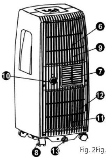
Fig. 2 Fig. 1
Front (fig 1)
- Control panel
- Control lever for air deflector (manual adjustment)
- Handle (on both sides)
- Receiver for remote control signal
- Panel
Back (fig 2)
- Top air filter (inside grille)
- Air outlet
- Wheel
- Air inlet
- Drain opening
- Air inlet
- Bottom air filter (inside grille)
- Drain opening for bottom tray
Operating Conditions
The permitted operating temperatures for the appliance are shown in the table below.
| MODE ROOM TEMpERATURE | |
| COOL 17–35°C | |
| DRY 13–35°C | |
| HEAT (heat pump) 5–30°C | |
| HEAT (electric heater) ≤ 30°C |
ACCESSORIES
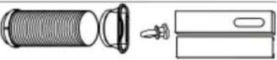 or or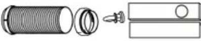 | Outlet hose (included), adapter B (flat or round nozzle depending on model), window insert and screw (*) | 1 set |
| [ZW4] | Adapter B (round nozzle) (*) 1 set | |
 | Wall outlet adapter A (*) 1 | |
 | Expansion plug and wood screw (*) | 4 |
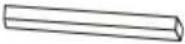 | Foam rubber seal (*) 3 | |
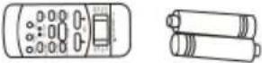 | Remote control med battery (only for models with remote control) | 1 set |
| [CW5S] | Drain hose 1 |
NOTE: Options (*) are not included on all models.
Check that all parts are included and are undamaged. Installation and use of accessories is described in the installation instructions.
NOTE: The diagrams in these instructions are only intended as illustrations. The appliance may deviate from the diagrams in these instructions.
TOOLS FOR MOUNTING WINDOW INSERT
- Medium Phillips screwdriver
- Tape measure or ruler
- Knife or scissors
- Saw (if window insert needs to be adjusted to width of window)
USE
CONTROL pANEL AND DISpLAY
Read these instructions carefully and familiarise yourself with the controls and how they are used. The appliance can be operated with the remote control or from the control panel.

Used to select operating mode. Press repeatedly to switch between AUTO, COOL, DRY and FAN modes. The status light indicates the set mode.
2. SLEEp
Used to activate SLEEP mode.
3. + and -
Used to increase/reduce the set point temperature in steps of 1^ C from 17 to 30^ C, or in steps of 1^ F from 62 to 88^ F, or to set the TIMER from 0 to 24 h.
NOTE: The temperature can be shown in °F or °C. To change units, press the + and - buttons at the same time for 3 seconds.
4. power switch
Starts/stops the appliance.
5. TIMER
Used together with the ‡ and ^ buttons to set start time AUTO ON and stop time AUTO OFF.
6. FAN
Press repeatedly to switch between LOW, HIGH and AUTO modes. The status light indicates the set mode, with the exception of AUTO. In AUTO mode all the status lights are off.
7. DISPLAY
Shows the set temperature in °C or °F (no unit shown for °F) and timer settings.
The room temperature is shown in DRY and FAN mode.
ERROR CODES
ERROR CODE MEANING ACTION
| E1- | Error from room temperature sensor. | ⇒ | Unplug and plug in the power cord.Contact your dealer if the fault remains. |
| E2- | Error from evaporator temperature sensor. | ⇒ | Unplug and plug in the power cord.Contact your dealer if the fault remains. |
| E4- Display communication error.INFORMATION CODE MEANING ACTION | ⇒ | Unplug and plug in the power cord.Contact your dealer if the fault remains. | |
| P1- The bottom tray is full. | ⇒ | Connect the drain hose and drain off the water. Contact your dealer if the fault remains. | |
NOTE: If there are several errors, the error codes are shown in the priority order E4–E2–E1–P1
ENERGY SAVER MODE
When the ambient temperature is lower (cooling) than the set point temperature for a set time the appliance automatically switches to energy saving mode. The status light goes on and the compressor and/or fan motor stops. When the ambient temperature is higher (cooling) than the set point temperature for a set time the appliance automatically switches to energy saving mode. The status light goes off and the compressor and/or fan motor starts.
USE
Cooling mode
- Press the MODE button repeatedly until the COOL status light goes on.
- Set the required temperature with the ▲ and ▼buttons. The temperature can be set from 17 to 30°C or from 62 to 88°F.
- Press the FAN SPEED button to set the fan speed.
DRY mode
- Press the MODE button repeatedly until the DRY status light goes on.
- In this mode it is not possible to adjust the set point temperature or fan speed.
- Keep doors and windows closed for best dehumidification function.
- Do not lead the hose through the window.
AUTO mode
- In AUTO mode the appliance runs in cooling or heating mode, depending on the room temperature the set point temperature.
- The appliance automatically maintains the room temperature close to the set temperature.
- In AUTO mode it is not possible to set the fan speed.
NOTE: In AUTO mode both the status light for AUTO mode and the status light for the actual mode go on.
FAN mode
- Press the MODE button repeatedly until the FAN status light goes on.
- Press the FAN SPEED button to set the fan speed. It is not possible to set the temperature.
- Do not lead the hose through the window.
TIMER mode
- When the appliance is running the stop delay can be activated when the TIMER button is pressed. The TIMER OFF status light goes on. Press the TIMER button once to activate the start delay setting. The TIMER ON status light goes on.
- When the appliance is switched off the start delay is activated when the TIMER button is pressed. The TIMER OFF status light goes on. Press the TIMER button once to activate the stop delay setting. The TIMER OFF status light goes on.
- Press in the ▲ or ▼button to change the time, in steps of 0.5 hours up to 10 hours and steps of 1 hour from 10 to 24 hours. The control system counts down the time to start/stop.
- The set time is shown for 5 seconds then the display automatically returns to show the current temperature setting.
- You can stop the countdown at any time to start/stop by switching off or starting the appliance, or by setting the time to 0.0.
- The timer function is also interrupted if there is an E1 or E2 error.
SLEEp/ECO mode
Pressing this button increases (cooling) the set temperature by 1^ C or 1^ F after 30 minutes. After another 30 minutes the set temperature increases (cooling) by another 1^ C or 1^ F. The new temperature is maintained for 7 hours, after which the original set temperature is restored. Sleep/Eco mode then finishes and the appliance runs with the original settings.
NOTE: This mode cannot be used in FAN or DRY mode.
MISCELLANEOUS
Automatic restart (some models)
When the power supply is reset after a power failure the appliance restarts with the previously set function.
Start delay 3 minutes
When the appliance has been stopped it will not start for 3 minutes. This is a safety function, and is completely normal. The appliance starts automatically after 3 minutes.
Setting the air direction

Fig. 4
• The air deflector can be set manually.
- Never overload the air deflector and do not block it with any objects – risk of material damage.
- Check that the air deflector is open when in use.
REMOTE CONTROL
Read the instructions carefully before use.
POSITIONING
- The remote control has a range of 8 metres. Point the remote control at the receiver on the appliance. An audio prompt confirms its reception.

IMpORTANT:
- Doors and curtains etc. block the signal on the remote control.
- Do not expose the remote control to water or any other liquid. Do not expose the remote control to heat or direct sunlight.
- Sunlight or strong artificial light can interfere with the receiver. Protect the receiver from strong light.
- If the remote control affects other appliances in the vicinity, move the appliances or contact your dealer.
REpLACING THE BATTERIES

The remote control has two batteries (R03) under a cover on the back.
- Open the battery cover.
- Remove the old batteries and insert new batteries with the correct polarity.
- Replace the battery cover.
NOTE: All programs are deleted when the batteries are taken out and the remote control must be programmed again.
IMpORTANT:
- Do not mix old and new batteries, or different types of batteries.
- Remove the batteries if the appliance is not going to be used for 2 months, or more.
• Recycle used batteries in accordance with local regulations.
TECHNICAL DATA
| Model RG51B1/(C)EU, RG51B14/(C)E, RG51B31/(C)E | RG51B/(C)EU, RG51B16/(C)E, RG51B31/(C)EURG51B17/(C)EU, RG51B18/(C)E, RG51 B32/(C)EURG51B19/(C)E-M, RG51 B20/(C)E, RG51 B30/(C)EURG51B25/(C)E, RG51 B26/(C)EU, RG51 B27/(C)E, RG51B30/(C)E. |
| Rated voltage 3.0 V (batteries R03) | |
| Lowest voltage at which a signal can be given 2.0 V | |
| Range 8 m | |
| Operating temperature -5 to 60°C |
TEMpERATURE DISpLAY
Degrees Celsius (°C): RG51B14/(C)E, RG51B16/(C)E, RG51B18/(C)E, RG51B31/(C)E, RG51B19/(C)E-M, RG51B20/(C)E, RG51 B25/(C)E, RG51 B27/(C)E, RG51 B30/(C)E.
Degrees Fahrenheit (°F): RG51B/(C)EU, RG51B1/(C)EU, RG51B17/(C)EU, RG51B26/(C)EU, RG51B30/(C)EU, RG51B32/(C)EU, RG51B31/(C)EU.
FUNCTIONS
- Operating modes: AUTO, COOL, DRY, HEAT modes (not on models that only have cooling) and FAN.
- 24 hour timer
- Adjustable range for room temperature: 17 to 30°C and 62 to 88°F
- LCD
NOTE: The diagrams in these instructions are only intended as illustrations. The appliance may deviate from the diagrams in these instructions.
BUTTONS
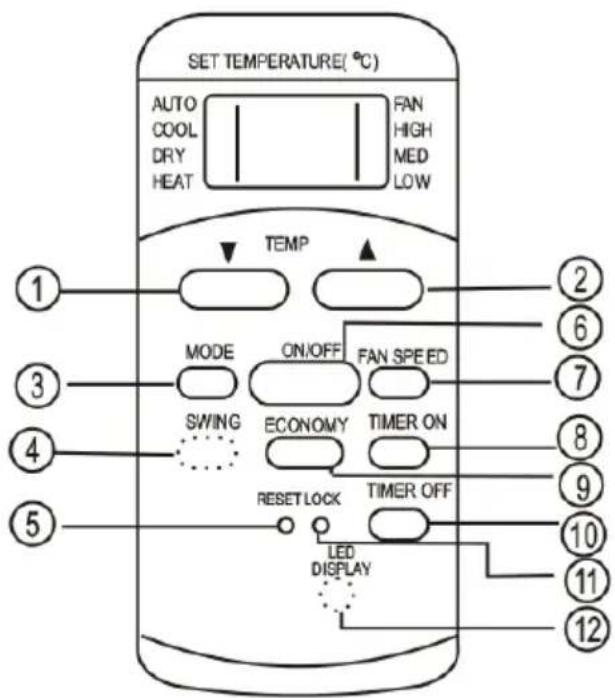
Model RG51B14/(C)E, RG51B16/(C)E, RG51B18/(C)E, RG51B19/(C)E-M, RG51B20/(C)E, RG51B31/(C)E, RG51B30/(C)E.
NOTE:
- Models RG51B16/(C)E, RG51B18/(C)E do not have the SWING function.
- Models RG51B18/(C)E, RG51B19/(C)E-M, RG51B20/(C)E do not have the LED DISPLAY button.
- Model RG51B19/(C)E-M does not have the MED FAN function.
- Model RG51B31/(C)E has the ECONO-MY button instead of the SLEEP button.
- Model RG51B30/(C)E does not have the MED FAN and SWING functions.
1. TEMp DOWN
Reduces the set point temperature in steps of 1^ C down to 17^ C, or in steps of 1^ F down to 62^ F.
2. TEMp Up
Increases the set point temperature in steps of 1^ C up to 30^ C, or in steps of 1^ F up to 88^ F.
3. MODE
Switches between modes in the following order.
NOTE: HEAT mode is only available on models with both heating and cooling.
4. SWING (some models)
Starts and stops the air deflector to adjust the required direction of the air.
5. RESET
Resets the remote control to default. All the settings made are lost.
6. ON/OFF
Switches the appliance on and off.
7. FAN SpEED
Switches between speed settings as follows. Some models do not have MED FAN mode.
8. TIMER ON
Press to activate the setting of start delay. Each time you press the button the setting increases in steps of 0.5 hours up to 10 hours and steps of 1 hour from 10 to 24 hours. Cancel this function by setting the time to 0.0.
9. ECONOMY (SLEEp)
This function produces a comfortable temperature and saves energy when you are sleeping. The function can only be used in COOL, HEAT and AUTO mode.

• Model RG51B25/(C)E, RG51 B27/(C)E.
NOTE: Model RG51B25/(C)E does not have the SWING function.
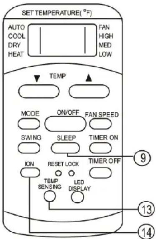
- Model RG51B17/(C)EU
NOTE: If the appliance is in SLEEP mode this is interrupted if the ON/OFF, FAN SPEED, SLEEP or MODE button is pressed.
10. TIMER OFF
Press to activate the setting of stop delay. Each time you press the button the setting increases in steps of 0.5 hours up to 10 hours and steps of 1 hour from 10 to 24 hours. Cancel this function by setting the time to 0.0.
11. LOCK
Press this depressed button to lock the actual settings. The remote control does not respond to pressing any other buttons than LOCK. This function is used to prevent unintentional changes. Press the button again to deactivate the function. When the function is activated a lock symbol is shown on the display on the remote control.
12. LED DISpLAY
Press this button to clear the display on the appliance. Press again to activate the display NOTE: Models RG51B18/(C)E, RG51B19/(C)E-M, RG51B20/(C)E do not have the LED DISPLAY button.
13. FOLLOW ME/TEMp SENSING
- Press this button to activate the FOLLOW ME function.
- The display on the remote control shows the actual temperature at the remote control when the Follow Me function is activated. The remote control sends a temperature signal to the appliance at 3 minute intervals until the Follow Me button is pressed again.
- The Follow Me function cannot be used in DRY and FAN mode.
- The function is deactivated if the appliance is switched off and switched on.
14. ION
Press this button to activate the ionisation unit, which helps to remove pollen and impurities from the air.
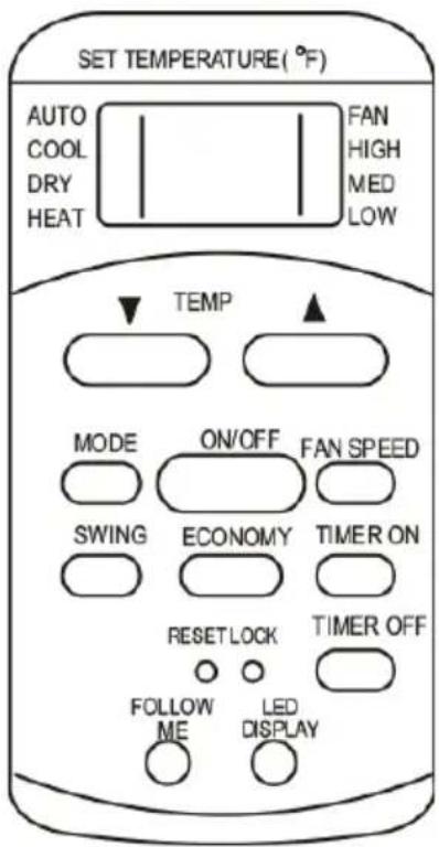
- Model RG51B1/(C)EU, RG51B/(C)EU, RG51B26/(C)EU, RG51B30/(C)EU, RG51B32/(C)EU, RG51B31/(C)EU.
NOTE: Model RG51B/(C)EU does not have the SWING and FOLLOW ME buttons. Model RG51B1/(C)EU does not have the FOLLOW ME button. Model RG51B30/(C)EU does not have the SWING and FOLLOW ME buttons or the MED FAN function and has the SLEEP button instead of the ECONOMY button. Model RG51B32/(C)EU does not have the FOLLOW ME button and the MED FAN function and has the SLEEP button instead of the ECONOMY button. Model RG51B31/(C)EU has the FOLLOW ME button.
DISPLAY READINGS

LOCK
Shown when the LOCK button is pressed. Goes off when the LOCK button is pressed again.
USING THE BUTTONS
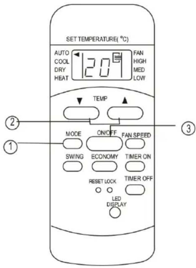
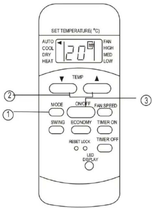
AUTO mode
Check that the appliance is connected to the mains.
The status light on the appliance goes on.
- Press the MODE button until AUTO mode is activated.
- Press the TEMP button to set the required temperature from 17 to 30^ in steps of 1^ or from 62 to 88^ in steps of 1^ .
- Press the ON/OFF button to start the appliance.
NOTE:
- In AUTO mode the appliance compares the actual room temperature with the set point temperature, which is set from the remote control and activates COOL, HEAT or DRY mode.
- In AUTO mode it is not possible to set the fan speed. The fan speed is controlled automatically.
- You can also set the required mode manually.
Cooling mode/heating mode/fan mode
Check that the appliance is connected to the mains.
- Press the MODE button until the required mode is activated (COOL, HEAT (only on models with both heating and cooling) or FAN).
- Press the TEMP button to set the required temperature from 17 to 30^ in steps of 1^ or from 62 to 88^ in steps of 1^ .
- Press the FAN SPEED to set the required fan speed to AUTO, LOW, MED or HIGH.
- Press the ON/OFF button to start the appliance.
NOTE: In FAN mode the set point temperature is not shown on display on the remote control and it is not possible to change the setting. Only steps 1, 3 and 4 should be carried out.
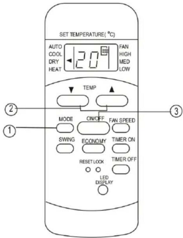
Dehumidification
Check that the appliance is connected to the mains.
The status light on the appliance goes on.
- Press the MODE button until DRY mode is activated.
- Press the TEMP button to set the required temperature from 17 to 30^ in steps of 1^ or from 62 to 88^ in steps of 1^ .
- Press the ON/OFF button to start the appliance.
NOTE: In DRY mode it is not possible to set the fan speed. The fan speed is controlled automatically.
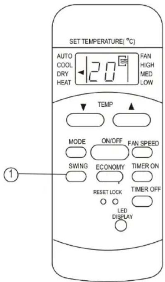
Swing (some models)
Press the SWING button to adjust the air deflector.
- Tap the button to swing the air deflector. The air deflector moves 6^ each time the button is pressed. Press repeatedly to move the air deflector to the required position.
NOTE: On some models the button only activates automatic swing.
- Automatic swing is activated if the button is pressed for more than 2 seconds. The air deflector swings backwards and forwards continuously. Press again to stop the movement.
NOTE: If the air deflector comes in a position that affects the cooling/heating function, the direction of the air is changed automatically.
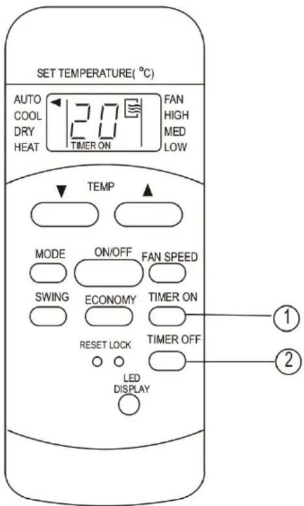
TIMER mode
Press the TIMER ON button to activate the setting of start delay. Press the TIMER OFF button to activate the setting of stop delay.
Setting the start delay
- Press TIMER ON. The display on the remote control shows TIMER ON, the last set start delay, and the status in h.
- Press the TIMER ON button once to set the required start delay. Each time you press the button the setting increases in steps of 0.5 hours up to 10 hours and steps of 1 hour from 10 to 24 hours.
- When the time for TIMER ON is set a signal is sent to the appliance after 0.5 seconds. After another 2 seconds the h status disappears and the set point temperature is shown again on the display.
Setting the stop delay
- Press TIMER OFF. The display on the remote control shows TIMER OFF, the last set stop delay and the status in h.
- Press the TIMER OFF button once to set the required stop delay. Each time you press the button the setting increases in steps of 0.5 hours up to 10 hours and steps of 1 hour from 10 to 24 hours.
- When the time for TIMER OFF is set a signal is sent to the appliance after 0.5 seconds. After another 2 seconds the h status disappears and the set point temperature is shown again on the display.
IMPORTANT: Only the following times can be set.
0.5, 1.0, 1.5, 2.0, 2.5, 3.0, 3.5, 4.0, 4.5, 5.0, 5.5, 6.0, 6.5, 7.0, 7.5, 8.0, 8.5, 9.0, 9.5, 10, 11, 12, 13, 14, 15, 16, 17, 18, 19, 20, 21, 22, 23 and 24.
EXAMPLE OF TIMER SETTING
6.0 h
TIMER ON

Settings 6 hours later


Settings
10 hours later
TIMER ON (automatic start)
The TIMER ON function is useful, for example, to start the appliance automatically before you get home.
Example
Follow the instructions below to set automatic start in 6 hours.
- Press TIMER ON. The display on the remote control shows the last set start delay and the status in h.
- Press the TIMER ON button repeatedly until 6:0h is shown on the display on the remote control.
- Wait about 3 seconds until the temperature display is reset. The function is now enabled.
TIMER OFF (automatic switching off)
The TIMER OFF function is useful, for example, to switch off the appliance automatically after you have gone to bed.
Example
Follow the instructions below to set automatic stop in 10 hours.
- Press TIMER OFF. The display on the remote control shows the last set stop delay and the status in h.
- Press the TIMER OFF button repeatedly until 10h is shown on the display on the remote control.
- Wait about 3 seconds until the temperature display is reset. The function is now enabled.
AUTOMATIC STARTING AND STOPPING


Settings
2 hours later 10 hours later


flowchart
graph LR
    A["Starting"] --> B["Switched off"]
    B --> C["Settings"]
    C --> D["2 hours later"]
    D --> E["10 hours later"]
    E --> F["Switching off"]
(on ← switching off ← starting)
This function is useful, for example, to switch off the appliance after you have gone to bed and to start it again before you get up.
Example
Follow the instructions below to set automatic stop in 2 hours and automatic start in 10 hours.
- Press TIMER OFF.
- Press the TIMER OFF button repeatedly until 2.0h is shown on the display on the remote control.
- Press TIMER ON.
- Press the TIMER ON button repeatedly until 10h is shown on the display on the remote control.
- Wait about 3 seconds until the temperature display is reset.
(switched off ← starting ← switching off)
This function is useful, for example, to start the appliance before you get up and to switch it off after you have left the house.
Example
Follow the instructions below to set automatic start in 2 hours and automatic stop in 5 hours.
- Press TIMER ON.
- Press the TIMER ON button repeatedly until 2.0h is shown on the display on the remote control.
- Press TIMER OFF.
- Press the TIMER OFF button repeatedly until 5.0h is shown on the display on the remote control.
- Wait about 3 seconds until the temperature display is reset.
IMPORTANT: The mode that comes up first (TIMER ON or TIMER OFF) takes place first.

ECONOMY (SLEEp)
- Pressing the ECONOMY button increases (cooling) or reduces (heating) the set temperature by 1°C or 1°F after 30 minutes.
• After another 30 minutes the set temperature increases (cooling) or reduces (heating) by another 1^ C or 1^ F. - The new temperature is maintained for 6 hours (7 hours on some models), after which the original set temperature is restored.
NOTE: On some models the set temperature increases (cooling) or reduces (heating) by 1^ C or 1^ F per hour for 2 hours. The new temperature is maintained for 5 hours, after which the appliance switches off.
NOTE: The ECONOMY/SLEEP function is only available in the COOL, HEAT and AUTO modes.
INSTALLATION

Fig. 5
Window insert Min. 67.5 cm Max. 123 cm
natural_image
Diagram of a refrigerant air conditioner unit with cooling fins and cooling tower (no text or labels)or

Window insert Min. 67.5 cm Max. 123 cm

natural_image
Line drawing of a portable air conditioner unit with cooling fins and a hanging handle (no text or symbols)Fig. 6

Window insert Min. 67.5 cm Max. 123 cm

natural_image
Line drawing of a portable air conditioner unit with airflow direction arrows (no text or symbols)
Window insert Min. 67.5 cm Max. 123 cm
natural_image
Line drawing of a portable air conditioner unit with airflow arrows (no text or symbols)Fig. 7
POSITIONING
- The appliance should be placed on a level, stable surface that can withstand the weight, to minimise noise and vibrations.
- Only move the appliance on the wheels on a level, smooth surface. Be careful when moving the appliance on carpets etc. Do not attempt to roll the appliance over objects.
- The appliance must only be connected to a correctly earthed mains outlet.
- Never block the air inlets or outlets on the appliance.
- Leave at least 30 cm of free space around the appliance to ensure adequate ventilation.
FITTING THE WINDOW INSERT
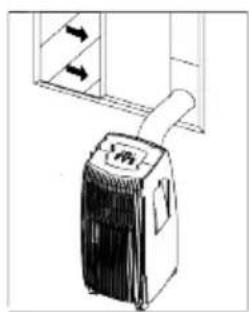
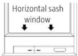
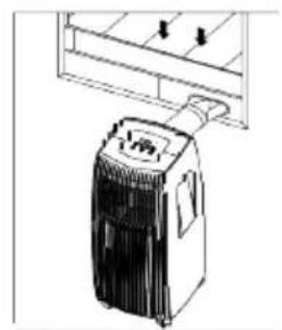
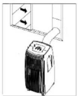
The window insert fits most sash windows that open horizontally or vertically. Some adjustment may be necessary. The maximum and minimum window openings are shown in fig. 6 and 7. The window insert is secured with a screw (fig. 7a).
NOTE: If the window opening is less than the minimum length of the window insert, the part with a hole can cut to a suitable length. Never cut through the hole in the window insert.

INSTALLATION IN SASH WINDOW THAT OpENS VERTICALLY(OpTION)

- Cut the self-adhesive foam rubber seal to a suitable length and fasten it to the bottom window frame. Fig. 8
- Align the window insert to the bottom window frame. Adjust the length of the window insert to the window. Cut the window insert if the height of the window is less than 67 cm. Open the window and put the window insert on the window frame (fig. 9).
- Cut the self-adhesive foam rubber seal to a suitable length and fasten it to the top edge of the window insert (fig. 10).
- Close the window so that it presses firmly against the window insert.
- Cut the foam rubber seal to a suitable length and seal the gap between the window halves (fig. 11).
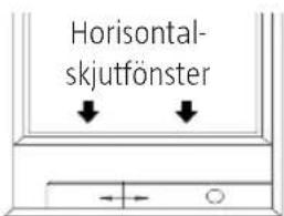
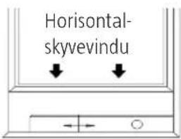
INSTALLATION IN SASH WINDOW THAT OpENS HORIZONTALLY(OpTION)

natural_image
Two technical line drawings of a mechanical or architectural component, one with a circular opening and the other with a circular hole (no text or symbols)Fig. 14
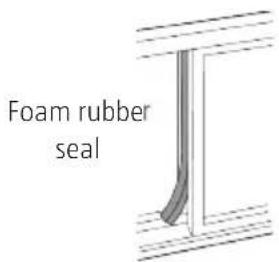
Fig. 15
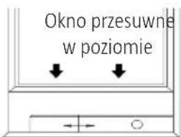
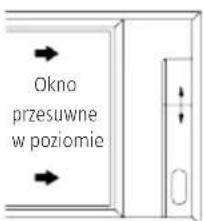
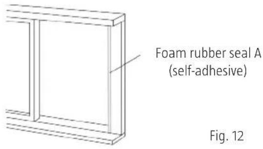
- Cut the self-adhesive foam rubber seal to a suitable length and fasten it to the window frame (fig. 12).
- Align the window insert to the window frame. Adjust the length of the window insert to the window. Cut the window insert if the height of the window is less than 67 cm.
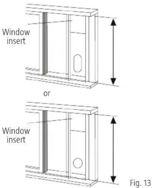
- Open the window and put the window insert on the window frame (fig. 13).
- Cut the self-adhesive foam rubber seal to a suitable length and fasten it to the edge of the window insert (fig. 14).
- Close the window so that it presses firmly against the window insert.
- Cut the foam rubber seal to a suitable length and seal the gap between the window halves (fig. 15).
INSTALLATION OF OUTLET HOSE

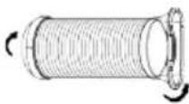
Fig. 16 Fig. 17

natural_image
Line drawing of a portable air conditioner unit with side-mounted cooling unit (no text or symbols)Fig. 18

Fig. 19

natural_image
Diagram showing a vehicle and a curved road with diagonal lines crossing (no text or symbols)Fig. 20
The outlet hose and adapter should be fitted, if necessary for the mode in use.
| COOL, AUTO Installed | |
| FAN, DEHUMIDIFY Not installed |
- Fit adapter B on the outlet hose (fig. 16 or 17). Fit the window insert according to the instructions above.
- Insert the outlet hose in the air outlet in the direction of the arrow (fig. 18).
THE OUTLET HOSE CAN BE LED THROUGH A WALL
(does not apply for appliances without adapter A, expander plug and wood screws as accessories).
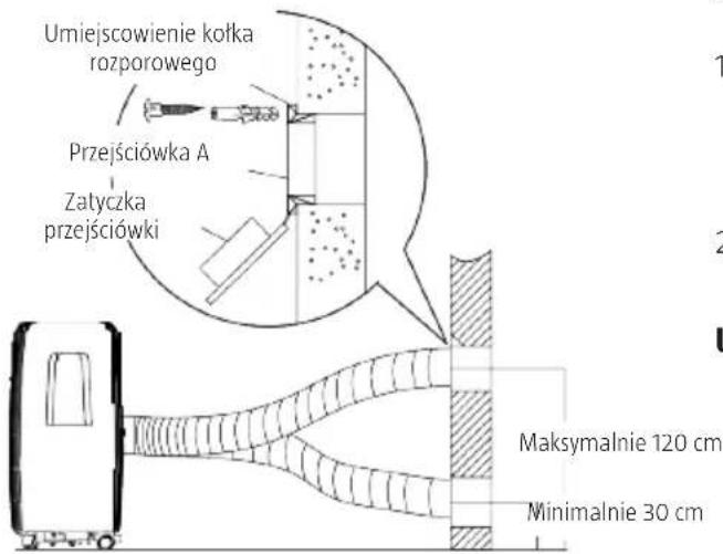
- Make a hole in the wall. Fit the outlet adapter A on the outside of the wall with 4 expander plugs and wood screws (fig. 18). Screw tight.
- Connect the outlet hose to outlet adapter A.
NOTE:
- Fit the adapter cover over the hole when the appliance is not in use.
- The outlet hose can be routed to a suitable length for the installation, but should be as short as possible.
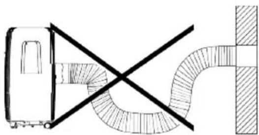
IMPORTANT
Do not bend the outlet hose too sharply (fig. 20).
IMPORTANT:
Check that there are no obstacles within 50 cm of the air outlet, otherwise the outlet system will not work properly.
INSTALLATION OF DRAIN

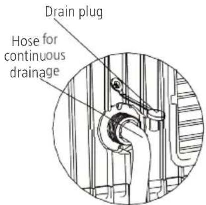
Fig. 22

Fig. 23
- In dehumidification mode, remove the drain plug on the back of the appliance and connect the drain hose (sold separately). Use 3/4" hose with 5/8" coupling with external thread. For models without drain connection, connect the drain hose to the hole. Lead the hose to a suitable drain (fig. 21 and 22).
- When the water level in the bottom tray reaches the specified level the appliance emits 8 beeps and the display shows P1. The air conditioning/dehumidification stops, but the fan continues to run.
- Carefully move the appliance to a suitable drain, remove the bottom plug and allow the water to run out (fig. 23). Replace the bottom drain plug and start the appliance. P1 disappears from the display. Contact your dealer if the fault remains.
NOTE: Remember to replace the bottom drain plug before starting the appliance.
Fig. 4
CARE AND MAINTENANCE

Fig. 24
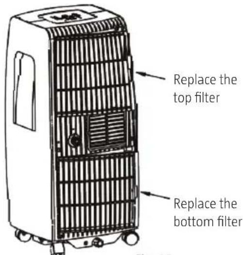
Fig. 25
IMpORTANT:
- Switch off the appliance and unplug the power cord before cleaning and/or maintenance.
- Do not use strong chemicals, detergents or solvents.
- Do not pour or rinse water on the appliance – risk of electric shock.
- A damaged power cord must be replaced by an authorised service centre, or other qualified personnel, to ensure safe use.
AIR FILTER
Clean the air filter at least every other week for best functionality.
Dismantling
The appliance has two filters. Pull the top and bottom filter in the direction of the arrow and fold down (fig. 24).
Cleaning
Wash the filters carefully with hot water and a mild detergent. Rinse and allow to dry.
Assembly
Replace the top and bottom filters (fig. 25).
NOTE: The filters can be removed from the grille.
CASING
Clean the casing with a soft cloth moistened with a mild detergent and wipe dry.
IF THE APPLIANCE IS NOT GOING TO BE USED FOR SOME TIME
- Remove the drain plug on the back of the appliance and connect a hose. Lead the hose to a suitable drain (fig. 22 and 23).
- Remove the bottom drain plug to empty the bottom tray (fig. 24).
- Allow the appliance to run in FAN mode for 6 hours in a warm room to dry the inside and to reduce the risk of mildew.
- Switch off the appliance, unplug the power cord, and hang up the cord and plug in the holders on the back. Remove the batteries from the remote control.
- Clean and replace the air filters.
pROBLEM POSSIBLE CAUSE ACTION
| The appliance does not start when the power switch is pressed. | Error code P1 (full bottom tray) is shown on the display). | ⇒ | Empty the bottom tray. |
| The room temperature is lower (cooling) or higher (heating) than the set point temperature. | ⇒ | Change the set point temperature. | |
| The appliance does not produce enough cooling. | Windows or doors open. | ⇒ | Close all the doors and windows. |
| Source of heat in the room. | ⇒ | Remove sources of heat if possible. | |
| Outlet hose blocked or not connected. | ⇒ | Connect the hose and arrange it so that it works properly. | |
| Set point temperature too high. | ⇒ | Set a lower set point temperature. | |
| Air filter blocked. | ⇒ | Clean the air filter. | |
| Noise or vibration. Surface is uneven or not level. | ⇒ | Put the appliance on a smooth, horizontal surface. | |
| Gurgling sound. | Caused by refrigerant in the appliance. | ⇒ | This is quite normal. |
Jula reserves the right to make changes. In the event of problems, please contact our service department. www.jula.com
natural_image
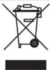
Simple line drawing of a trash bin with no visible text or symbolsCare for the environment!
Must not be discarded with household waste!
This product contains electrical or electronic components that should be recycled.
Leave the product for recycling at the designated station e.g. the clocal authority's recycling station.
- SVENSKA....7
- SÄKERHETSANVISNINGAR....7
- TEKNISKA DATA....8
- BESKRIVNING 9
- DRIFTFÖRHÅLLAnDEN....9
- VERKTYG FÖR MONTERING AV FÖNSTERINSATS 10
- ANVÄNDNING....11
- FELKODER....12
- ANVÄNDNING 13
- MONTERING....27
- UNDERHÅLL OCH SKÖTSEL ....32
- BRUK....40
- MONTERING 54
- VEDLIKEHOLD OG RENGJ∅RING 59
- KONSERWACJA I PIELEGNACJA 86
- SAFETY INSTRUCTIONS 88
- TECHNICAL DATA 89
- DESCRIPTION 90
- ERROR CODES....93
- INSTALLATION....108
- CARE AND MAINTENANCE....113
- SÄKERHETSANVISNINGAR
- ENERGISpARTIpS
- Framsida (fig 1)
- FUNKTIONER
- OBS!
- TEMp DOWN
- pLACERING
- STR∅MSpARETIpS
- Forside (fig. 1)
- Bakside (fig. 2)
- FUNKSJONER
- EKSEMPEL PÅ TIDSURINNSTILLING
- pLASSERING
- Verne om miljøet!
- przód (rys. 1)
- UWAGA!
- LOKALIZACJA
- Read the User Instructions carefully before use.
- IMpORTANT:
- WARNING:
- ENERGY SAVING TIPs
- DESCRIPTION
- pARTS
- Front (fig 1)
- Back (fig 2)
- Operating Conditions
- ACCESSORIES
- TOOLS FOR MOUNTING WINDOW INSERT
- USE
- CONTROL pANEL AND DISpLAY
- SLEEp
- + and -
- power switch
- TIMER
- FAN
- DISPLAY
- ERROR CODES
- NOTE: If there are several errors, the error codes are shown in the priority order E4–E2–E1–P1
- ENERGY SAVER MODE
- Cooling mode
- DRY mode
- AUTO mode
- NOTE: In AUTO mode both the status light for AUTO mode and the status light for the actual mode go on.
- FAN mode
- TIMER mode
- SLEEp/ECO mode
- MISCELLANEOUS
- Automatic restart (some models)
- Start delay 3 minutes
- REMOTE CONTROL
- POSITIONING
- REpLACING THE BATTERIES
- TECHNICAL DATA
- TEMpERATURE DISpLAY
- FUNCTIONS
- BUTTONS
- NOTE:
- TEMp Up
- MODE
- SWING (some models)
- RESET
- ON/OFF
- FAN SpEED
- TIMER ON
- ECONOMY (SLEEp)
- TIMER OFF
- LOCK
- LED DISpLAY
- FOLLOW ME/TEMp SENSING
- ION
- DISPLAY READINGS
- LOCK
- Cooling mode/heating mode/fan mode
- Dehumidification
- Swing (some models)
- Setting the start delay
- Setting the stop delay
- EXAMPLE OF TIMER SETTING
- TIMER ON (automatic start)
- Example
- TIMER OFF (automatic switching off)
- ECONOMY (SLEEp)
- INSTALLATION
- FITTING THE WINDOW INSERT
- INSTALLATION IN SASH WINDOW THAT OpENS VERTICALLY(OpTION)
- INSTALLATION IN SASH WINDOW THAT OpENS HORIZONTALLY(OpTION)
- INSTALLATION OF OUTLET HOSE
- THE OUTLET HOSE CAN BE LED THROUGH A WALL
- IMPORTANT
- CARE AND MAINTENANCE
- AIR FILTER
- Dismantling
- Cleaning
- Assembly
- NOTE: The filters can be removed from the grille.
- CASING
- IF THE APPLIANCE IS NOT GOING TO BE USED FOR SOME TIME
- Care for the environment!
Brand : Anslut
Model : 417-060
Category : Air conditioner